US9227097B2 - Fireproof rack and fireproof method thereof - Google Patents

Fireproof rack and fireproof method thereof Download PDF

Info

Publication number
US9227097B2
US9227097B2 US13/711,864 US201213711864A US9227097B2 US 9227097 B2 US9227097 B2 US 9227097B2 US 201213711864 A US201213711864 A US 201213711864A US 9227097 B2 US9227097 B2 US 9227097B2
Authority
US
United States
Prior art keywords
fireproof
moveable frame
rack
frame
linkage
Prior art date
Legal status (The legal status is an assumption and is not a legal conclusion. Google has not performed a legal analysis and makes no representation as to the accuracy of the status listed.)
Active, expires
Application number
US13/711,864
Other versions
US20140138103A1 (en
Inventor
Po-Kuan Lee
Chung-Ting Kao
Current Assignee (The listed assignees may be inaccurate. Google has not performed a legal analysis and makes no representation or warranty as to the accuracy of the list.)
Institute for Information Industry
Original Assignee
Institute for Information Industry
Priority date (The priority date is an assumption and is not a legal conclusion. Google has not performed a legal analysis and makes no representation as to the accuracy of the date listed.)
Filing date
Publication date
Application filed by Institute for Information Industry filed Critical Institute for Information Industry
Assigned to INSTITUTE FOR INFORMATION INDUSTRY reassignment INSTITUTE FOR INFORMATION INDUSTRY ASSIGNMENT OF ASSIGNORS INTEREST (SEE DOCUMENT FOR DETAILS). Assignors: KAO, CHUNG-TING, LEE, PO-KUAN
Publication of US20140138103A1 publication Critical patent/US20140138103A1/en
Application granted granted Critical
Publication of US9227097B2 publication Critical patent/US9227097B2/en
Active legal-status Critical Current
Adjusted expiration legal-status Critical

Links

Images

Classifications

    • AHUMAN NECESSITIES
    • A62LIFE-SAVING; FIRE-FIGHTING
    • A62CFIRE-FIGHTING
    • A62C99/00Subject matter not provided for in other groups of this subclass
    • A62C99/0009Methods of extinguishing or preventing the spread of fire by cooling down or suffocating the flames
    • AHUMAN NECESSITIES
    • A62LIFE-SAVING; FIRE-FIGHTING
    • A62CFIRE-FIGHTING
    • A62C3/00Fire prevention, containment or extinguishing specially adapted for particular objects or places
    • A62C3/16Fire prevention, containment or extinguishing specially adapted for particular objects or places in electrical installations, e.g. cableways

Definitions

  • the present invention relates to a fireproof rack, and in particular, a fireproof rack utilizing fireproof liquid for fire resistance.
  • U.S. Pat. No. 6,158,833 discloses a fireproof rack providing a storage space surrounded by multiple thermal insulation walls.
  • the thermal insulation wall is also expensive. Additionally, when the thermal insulation wall is broken, fireproofing ability decreases.
  • a fireproof rack for protecting an object.
  • the fireproof rack includes a major frame, a moveable frame, a fireproof chamber and a fireproof liquid.
  • the moveable frame is slidably connected to the major frame, and the moveable frame slides between a first position and a second position relative to the major frame, and the object is disposed in the moveable frame, and the moveable frame and the object are in the first position under an operation mode. Under a fireproof mode, the moveable frame and the object slide to the second position, and are received in the fireproof chamber.
  • the fireproof liquid is located in the fireproof chamber. When the moveable frame and the object are in the second position, the object is soaked in the fireproof liquid.
  • a fireproof method for protecting an object including the following steps. First, a fireproof rack is provided, wherein the fireproof rack comprises a major frame, a moveable frame, a fireproof chamber and a fireproof liquid, and the object is disposed in the moveable frame. Then, under a fireproof mode, the moveable frame slides from a first position to a second position relative to the major frame, and the moveable frame and the object are received in the fireproof chamber, wherein the object is soaked in the fireproof liquid when the moveable frame and the object are in the second position.
  • a computer server is soaked in the fireproof liquid, which improves the fireproofing function.
  • the fireproof chamber can be a standard cabinet, which has a simple structure, low cost and low structural strength.
  • FIG. 1A shows the fireproof rack of the embodiment of the invention under the operation mode
  • FIG. 1B shows the fireproof rack of the embodiment of the invention under the fireproof mode
  • FIG. 2A shows the temperature sensing unit, the active unit and the positioning unit under the operation mode
  • FIG. 2B shows the temperature sensing unit, the active unit and the positioning unit under the fireproof mode
  • FIG. 3 shows the fireproof rack of another embodiment of the invention.
  • FIGS. 4A and 4B show the fireproof rack of the embodiment of the invention, wherein the wire of the computer server is prevented from interfering with the fireproof chamber.
  • FIGS. 1A and 1B show a fireproof rack 1 of an embodiment of the invention for protecting a computer server 9 .
  • the fireproof rack 1 comprises a major frame 10 , a moveable frame 20 , a fireproof chamber 30 and a fireproof liquid 40 .
  • the moveable frame 20 is slidably connected to the major frame 10 , wherein the moveable frame 20 slides between a first position ( FIG. 1A ) and a second position ( FIG. 1B ) relative to the major frame 10 , wherein the computer server 9 (protection object) is disposed in the moveable frame 20 .
  • the moveable frame 20 and the computer server 9 are in the first position allowing users to operate the computer server 9 .
  • the moveable frame 20 and the computer server 9 slide from the first position to the second position, and are received in the fireproof chamber 30 .
  • the fireproof liquid 40 is located in the fireproof chamber 30 .
  • the computer server 9 is soaked in the fireproof liquid 40 .
  • the fireproof liquid 40 can be liquid with high electric resistance, for example, deionized water or silicone oil.
  • the unused fireproof liquid 40 can be packaged in the liquid package 41 ( FIG. 1A ).
  • the moveable frame 20 comprises a spiny portion 21 , and when the moveable frame 20 and the computer server 9 are moved from the first position to the second position, the spiny portion 21 penetrates the liquid package 41 to fill the fireproof chamber 30 with the fireproof liquid 40 .
  • a vacuum vapor deposition process can be utilized to coat, for example, poly-p-xylene on the computer server 9 to form a nano-scale waterproof film.
  • the nano-scale waterproof film can prevent circuit shorting caused by impure water.
  • the fireproof liquid 40 is not limited to liquid with high electric resistance.
  • the fireproof rack 1 further comprises a fireproof shield 50 , wherein the fireproof shield 50 is disposed on the moveable frame 20 , and the computer server 9 is located between the fireproof shield 50 and the spiny portion 21 .
  • the fireproof shield 50 covers the fireproof chamber 30 .
  • the fireproof rack 1 further comprises a temperature sensing unit 60 , an active unit 70 and at least one positioning unit 80 .
  • the temperature sensing unit 60 is connected to the active unit 70
  • the positioning unit 80 is connected to the active unit 70 .
  • the positioning unit 80 fixes the moveable frame 20 in the first position relative to the major frame 10 .
  • the active unit 70 activates the positioning unit 80 to release the moveable frame 20 according a sensing result of the temperature sensing unit 60 , wherein the moveable frame 20 slides relative to the major frame 10 .
  • the temperature sensing unit 60 comprises a glass alarm sensor 61 , a transmission rod 62 , a first elastic element 63 , a restriction element 64 , a pushing post 65 and a second elastic element 66 .
  • the glass alarm sensor 61 abuts an end of the transmission rod 62
  • the first elastic element 63 is connected to the transmission rod 62
  • the restriction element 64 is connected to another end of the transmission rod 62
  • the pushing post 65 abuts the restriction element 64
  • the second elastic element 66 is telescoped on the pushing post 65 .
  • the fireproof rack 1 When the glass alarm sensor 61 is broken, the fireproof rack 1 is under the fireproof mode, wherein the first elastic element 63 provides a pull force to rotate the transmission rod 62 , the restriction element 64 is moved by the transmission rod 62 to be separated from the pushing post 65 , and the pushing post 65 is moved by the second elastic element 66 .
  • the active unit 70 comprises a block 71 , a third elastic element 72 , a transmission element 73 , a gear 74 , a reel 75 , at least one line 76 , and at least one hook 77 .
  • the pushing post 65 abuts the block 71
  • the third elastic element 72 is connected to the transmission element 73
  • the block 71 abuts the transmission element 73 to restrict a position of the transmission element 73
  • the gear 74 meshes the transmission element 73
  • the gear 74 is connected to the reel 75
  • an end of the line 76 is connected to the reel 75
  • the hook 77 is connected to another end of the line 76 .
  • a hole 78 is formed on the block 71 .
  • the pushing post 65 pushes the block 71 , and the block 71 is moved such that the transmission element 73 is pushed by the third elastic element 72 to be partially inserted into the hole 78 .
  • the transmission element 73 rotates the gear 74 and the reel 75 , and the reel 75 winds up the line 76 .
  • the positioning unit 80 comprises a first linkage 81 , a second linkage 82 and a third linkage 83 , and the first linkage 81 is connected to the second linkage 82 , the second linkage 82 is connected to the third linkage 83 , the hook 77 is connected to an end of the first linkage 81 , and the third linkage 83 abuts the moveable frame 20 .
  • the line 76 is winded to pull the hook 77 and the first linkage 81 , the second linkage 82 is rotated by the first linkage 81 , and the third linkage 83 is separated from the moveable frame 20 by the second linkage 82 to release the moveable frame 20 .
  • the fireproof rack of the embodiment of the invention Utilizing the fireproof rack of the embodiment of the invention, a computer server is soaked in the fireproof liquid, and the fireproofing function is improved.
  • the fireproof chamber can be a standard cabinet, which has a simple structure, low cost and low structural strength.
  • FIG. 3 shows a fireproof rack 1 ′ of another embodiment of the invention, wherein a storage unit 91 of the computer server 9 is below the fireproof shield 50 . Under the fireproof mode, the storage unit 91 enters the fireproof chamber 30 to be protected, and an operation unit 92 of the computer server 9 is exposed on the outside of the fireproof chamber 30 . Therefore, the dimension of the fireproof chamber 30 can be reduced, and the environmental space can be used more effectively.
  • the length of the fireproof chamber 30 is longer than the length of the computer server 9 .
  • a wire 93 of the computer server 9 is prevented from interfering with the fireproof chamber 30 , and the computer server 9 can smoothly enter the fireproof chamber 30 .
  • a wheel 11 can be disposed on the major frame 10 . The position of the wheel 11 can be changed with the position of the moveable frame 20 , and the wire 93 is guided by the wheel 11 to prevent the wire 93 from interfering with the fireproof chamber 30 .

Landscapes

  • Health & Medical Sciences (AREA)
  • Public Health (AREA)
  • Business, Economics & Management (AREA)
  • Emergency Management (AREA)
  • Casings For Electric Apparatus (AREA)
  • Cooling Or The Like Of Electrical Apparatus (AREA)

Abstract

A fireproof rack for protecting an object is provided. The fireproof rack includes a major frame, a moveable frame, a fireproof chamber and a fireproof liquid. The moveable frame is slidably connected to the major frame, and the moveable frame slides between a first position and a second position relative to the major frame, and the object is disposed in the moveable frame, and the moveable frame and the object are in the first position under an operation mode. Under a fireproof mode, the moveable frame and the object slide to the second position, and are received in the fireproof chamber. The fireproof liquid is located in the fireproof chamber. When the moveable frame and the object are in the second position, the object is soaked in the fireproof liquid.

Description

CROSS REFERENCE TO RELATED APPLICATIONS
This Application claims priority of Taiwan Patent Application No. 101143190, filed on Nov. 20, 2012, the entirety of which is incorporated by reference herein.
BACKGROUND OF THE INVENTION
1. Field of the Invention
The present invention relates to a fireproof rack, and in particular, a fireproof rack utilizing fireproof liquid for fire resistance.
2. Description of the Related Art
Conventional fireproof racks, such as U.S. Pat. No. 6,536,169, have a specially designed rack body, which is filled with solid firestop material to protect computer servers thereon. However, the specially designed rack body is expensive, and has failed to gain popularity.
U.S. Pat. No. 6,158,833 discloses a fireproof rack providing a storage space surrounded by multiple thermal insulation walls. However, the thermal insulation wall is also expensive. Additionally, when the thermal insulation wall is broken, fireproofing ability decreases.
Therefore, a fireproof rack having a simple design, low cost, and sufficient fireproofing function is required by users of computer servers.
BRIEF SUMMARY OF THE INVENTION
In one embodiment of the invention, a fireproof rack for protecting an object is provided. The fireproof rack includes a major frame, a moveable frame, a fireproof chamber and a fireproof liquid. The moveable frame is slidably connected to the major frame, and the moveable frame slides between a first position and a second position relative to the major frame, and the object is disposed in the moveable frame, and the moveable frame and the object are in the first position under an operation mode. Under a fireproof mode, the moveable frame and the object slide to the second position, and are received in the fireproof chamber. The fireproof liquid is located in the fireproof chamber. When the moveable frame and the object are in the second position, the object is soaked in the fireproof liquid.
A fireproof method for protecting an object is provided, including the following steps. First, a fireproof rack is provided, wherein the fireproof rack comprises a major frame, a moveable frame, a fireproof chamber and a fireproof liquid, and the object is disposed in the moveable frame. Then, under a fireproof mode, the moveable frame slides from a first position to a second position relative to the major frame, and the moveable frame and the object are received in the fireproof chamber, wherein the object is soaked in the fireproof liquid when the moveable frame and the object are in the second position.
Utilizing the fireproof rack of the embodiment of the invention, a computer server is soaked in the fireproof liquid, which improves the fireproofing function. The fireproof chamber can be a standard cabinet, which has a simple structure, low cost and low structural strength.
A detailed description is given in the following embodiments with reference to the accompanying drawings.
BRIEF DESCRIPTION OF THE DRAWINGS
The present invention can be more fully understood by reading the subsequent detailed description and examples with references made to the accompanying drawings, wherein:
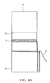
FIG. 1A shows the fireproof rack of the embodiment of the invention under the operation mode;
FIG. 1B shows the fireproof rack of the embodiment of the invention under the fireproof mode;
FIG. 2A shows the temperature sensing unit, the active unit and the positioning unit under the operation mode;
FIG. 2B shows the temperature sensing unit, the active unit and the positioning unit under the fireproof mode;
FIG. 3 shows the fireproof rack of another embodiment of the invention; and
FIGS. 4A and 4B show the fireproof rack of the embodiment of the invention, wherein the wire of the computer server is prevented from interfering with the fireproof chamber.
DETAILED DESCRIPTION OF THE INVENTION
The following description is of the best-contemplated mode of carrying out the invention. This description is made for the purpose of illustrating the general principles of the invention and should not be taken in a limiting sense. The scope of the invention is best determined by reference to the appended claims.
FIGS. 1A and 1B show a fireproof rack 1 of an embodiment of the invention for protecting a computer server 9. The fireproof rack 1 comprises a major frame 10, a moveable frame 20, a fireproof chamber 30 and a fireproof liquid 40. The moveable frame 20 is slidably connected to the major frame 10, wherein the moveable frame 20 slides between a first position (FIG. 1A) and a second position (FIG. 1B) relative to the major frame 10, wherein the computer server 9 (protection object) is disposed in the moveable frame 20.
With reference to FIG. 1A, under an operation mode, the moveable frame 20 and the computer server 9 are in the first position allowing users to operate the computer server 9.
With reference to FIG. 1B, under a fireproof mode, the moveable frame 20 and the computer server 9 slide from the first position to the second position, and are received in the fireproof chamber 30. The fireproof liquid 40 is located in the fireproof chamber 30. When the moveable frame 20 and the computer server 9 are in the second position, the computer server 9 is soaked in the fireproof liquid 40.
The fireproof liquid 40 can be liquid with high electric resistance, for example, deionized water or silicone oil. The unused fireproof liquid 40 can be packaged in the liquid package 41 (FIG. 1A). The moveable frame 20 comprises a spiny portion 21, and when the moveable frame 20 and the computer server 9 are moved from the first position to the second position, the spiny portion 21 penetrates the liquid package 41 to fill the fireproof chamber 30 with the fireproof liquid 40.
In one embodiment, a vacuum vapor deposition process can be utilized to coat, for example, poly-p-xylene on the computer server 9 to form a nano-scale waterproof film. The nano-scale waterproof film can prevent circuit shorting caused by impure water. In this embodiment, the fireproof liquid 40 is not limited to liquid with high electric resistance.
In one embodiment, the fireproof rack 1 further comprises a fireproof shield 50, wherein the fireproof shield 50 is disposed on the moveable frame 20, and the computer server 9 is located between the fireproof shield 50 and the spiny portion 21. When the moveable frame 20 and the computer server 9 are in the second position, the fireproof shield 50 covers the fireproof chamber 30.
For switching the fireproof rack 1 from the operation mode to the fireproof mode automatically, the fireproof rack 1 further comprises a temperature sensing unit 60, an active unit 70 and at least one positioning unit 80. The temperature sensing unit 60 is connected to the active unit 70, and the positioning unit 80 is connected to the active unit 70. Under the operation mode, the positioning unit 80 fixes the moveable frame 20 in the first position relative to the major frame 10. Under the fireproof mode, the active unit 70 activates the positioning unit 80 to release the moveable frame 20 according a sensing result of the temperature sensing unit 60, wherein the moveable frame 20 slides relative to the major frame 10.
With reference to FIGS. 2A and 2B, the temperature sensing unit 60 comprises a glass alarm sensor 61, a transmission rod 62, a first elastic element 63, a restriction element 64, a pushing post 65 and a second elastic element 66. The glass alarm sensor 61 abuts an end of the transmission rod 62, the first elastic element 63 is connected to the transmission rod 62, the restriction element 64 is connected to another end of the transmission rod 62, the pushing post 65 abuts the restriction element 64, and the second elastic element 66 is telescoped on the pushing post 65.
When the glass alarm sensor 61 is broken, the fireproof rack 1 is under the fireproof mode, wherein the first elastic element 63 provides a pull force to rotate the transmission rod 62, the restriction element 64 is moved by the transmission rod 62 to be separated from the pushing post 65, and the pushing post 65 is moved by the second elastic element 66.
The active unit 70 comprises a block 71, a third elastic element 72, a transmission element 73, a gear 74, a reel 75, at least one line 76, and at least one hook 77. The pushing post 65 abuts the block 71, the third elastic element 72 is connected to the transmission element 73, the block 71 abuts the transmission element 73 to restrict a position of the transmission element 73, the gear 74 meshes the transmission element 73, the gear 74 is connected to the reel 75, an end of the line 76 is connected to the reel 75, and the hook 77 is connected to another end of the line 76.
A hole 78 is formed on the block 71. Under the fireproof mode, the pushing post 65 pushes the block 71, and the block 71 is moved such that the transmission element 73 is pushed by the third elastic element 72 to be partially inserted into the hole 78. Simultaneously, the transmission element 73 rotates the gear 74 and the reel 75, and the reel 75 winds up the line 76.
The positioning unit 80 comprises a first linkage 81, a second linkage 82 and a third linkage 83, and the first linkage 81 is connected to the second linkage 82, the second linkage 82 is connected to the third linkage 83, the hook 77 is connected to an end of the first linkage 81, and the third linkage 83 abuts the moveable frame 20.
Under the fireproof mode, the line 76 is winded to pull the hook 77 and the first linkage 81, the second linkage 82 is rotated by the first linkage 81, and the third linkage 83 is separated from the moveable frame 20 by the second linkage 82 to release the moveable frame 20.
Utilizing the fireproof rack of the embodiment of the invention, a computer server is soaked in the fireproof liquid, and the fireproofing function is improved. The fireproof chamber can be a standard cabinet, which has a simple structure, low cost and low structural strength.
FIG. 3 shows a fireproof rack 1′ of another embodiment of the invention, wherein a storage unit 91 of the computer server 9 is below the fireproof shield 50. Under the fireproof mode, the storage unit 91 enters the fireproof chamber 30 to be protected, and an operation unit 92 of the computer server 9 is exposed on the outside of the fireproof chamber 30. Therefore, the dimension of the fireproof chamber 30 can be reduced, and the environmental space can be used more effectively.
With reference to FIG. 4A, in one embodiment of the invention, the length of the fireproof chamber 30 is longer than the length of the computer server 9. When the computer server 9 enters the fireproof chamber 30, a wire 93 of the computer server 9 is prevented from interfering with the fireproof chamber 30, and the computer server 9 can smoothly enter the fireproof chamber 30. With reference to FIG. 4B, in one embodiment, a wheel 11 can be disposed on the major frame 10. The position of the wheel 11 can be changed with the position of the moveable frame 20, and the wire 93 is guided by the wheel 11 to prevent the wire 93 from interfering with the fireproof chamber 30.
Use of ordinal terms such as “first”, “second”, “third”, etc., in the claims to modify a claim element does not by itself connote any priority, precedence, or order of one claim element over another or the temporal order in which acts of a method are performed, but are used merely as labels to distinguish one claim element having a certain name from another element having a same name (but for use of the ordinal term) to distinguish the claim elements.
While the invention has been described by way of example and in terms of the preferred embodiments, it is to be understood that the invention is not limited to the disclosed embodiments. To the contrary, it is intended to cover various modifications and similar arrangements (as would be apparent to those skilled in the art). Therefore, the scope of the appended claims should be accorded the broadest interpretation so as to encompass all such modifications and similar arrangements.

Claims (14)

What is claimed is:
1. A fireproof rack, for protecting an object, comprising:
a major frame;
a moveable frame, slidably connected to the major frame, wherein the moveable frame slides between a first position and a second position relative to the major frame, and the object is disposed in the moveable frame, and the moveable frame and the object are in the first position under an operation mode;
a fireproof chamber, wherein under a fireproof mode, the moveable frame and the object slide to the second position, and are received in the fireproof chamber;
a fireproof liquid, located in the fireproof chamber, wherein when the moveable frame and the object are in the second position, the object is soaked in the fireproof liquid; and
a liquid package, wherein the fireproof liquid is contained in the liquid package, and the moveable frame comprises a spiny portion, and when the moveable frame and the object are moved from the first position to the second position, the spiny portion penetrates the liquid package to fill the fireproof chamber with the fireproof liquid.
2. The fireproof rack as claimed in claim 1, wherein the fireproof liquid comprises deionized water or silicone oil.
3. The fireproof rack as claimed in claim 1, further comprising a fireproof shield, wherein the fireproof shield is disposed on the moveable frame, and the object is located between the fireproof shield and the spiny portion, and when the moveable frame and the object are in the second position, the fireproof shield covers the fireproof chamber.
4. The fireproof rack as claimed in claim 1, further comprising a temperature sensing unit, an active unit and at least one positioning unit, wherein the temperature sensing unit is connected to the active unit, and the positioning unit is connected to the active unit, and under the operation mode, the positioning unit fixes the moveable frame in the first position relative to the major frame, and under the fireproof mode, the active unit activates the positioning unit to release the moveable frame according a sensing result of the temperature sensing unit, wherein the moveable frame slides relative to the major frame.
5. The fireproof rack as claimed in claim 4, wherein the temperature sensing unit comprises a glass alarm sensor, a transmission rod, a first elastic element, a restriction element, a pushing post and a second elastic element, and the glass alarm sensor abuts an end of the transmission rod, the first elastic element is connected to the transmission rod, and the restriction element is connected to another end of the transmission rod, the pushing post abuts the restriction element, and the second elastic element is telescoped on the pushing post.
6. The fireproof rack as claimed in claim 5, wherein when the glass alarm sensor is broken, the fireproof rack is under the fireproof mode, and the first elastic element provides a pull force to rotate the transmission rod, and the restriction element is moved by the transmission rod to be separated from the pushing post, wherein the pushing post is moved by the second elastic element.
7. The fireproof rack as claimed in claim 5, wherein the active unit comprises a block, a third elastic element, a transmission element, a gear, a reel, at least one line, and at least one hook, and the pushing post abuts the block, the third elastic element is connected to the transmission element, the block abuts the transmission element to restrict a position of the transmission element, the gear meshes the transmission element, the gear is connected to the reel, an end of the line is connected to the reel, and the hook is connected to another end of the line.
8. The fireproof rack as claimed in claim 7, wherein under the fireproof mode, the pushing post pushes the block, the block is moved to release the transmission element, the transmission element is pushed by the third elastic element to rotate the gear and the reel, and the reel winds up the line.
9. The fireproof rack as claimed in claim 8, wherein a hole is formed on the block, wherein under the fireproof mode, the transmission element is pushed by the third elastic element to be partially inserted into the hole.
10. The fireproof rack as claimed in claim 7, wherein the positioning unit comprises a first linkage, a second linkage and a third linkage, and the first linkage is connected to the second linkage, the second linkage is connected to the third linkage, the hook is connected to an end of the first linkage, and the third linkage abuts the moveable frame.
11. The fireproof rack as claimed in claim 10, wherein under the fireproof mode, the line is winded to pull the hook and the first linkage, the second linkage is rotated by the first linkage, and the third linkage is separated from the moveable frame by the second linkage to release the moveable frame.
12. A fireproof method for protecting an object, comprising:
providing a fireproof rack, wherein the fireproof rack comprises a major frame, a moveable frame, a fireproof chamber and a fireproof liquid, and the object is disposed in the moveable frame;
under a fireproof mode, the moveable frame sliding from a first position to a second position relative to the major frame, and receiving the moveable frame and the object in the fireproof chamber; wherein the object is soaked in the fireproof liquid when the moveable frame and the object are in the second position,
wherein the fireproof rack further comprises a liquid package, wherein the fireproof liquid is contained in the liquid package, and the moveable frame comprises a spiny portion, and when the moveable frame and the object are moved from the first position to the second position, the spiny portion penetrates the liquid package to fill the fireproof chamber with the fireproof liquid.
13. The fireproof method as claimed in claim 12, wherein the fireproof rack further comprises a fireproof shield, wherein the fireproof shield is disposed on the moveable frame, and the object is located between the fireproof shield and the spiny portion, and when the moveable frame and the object are in the second position, the fireproof shield covers the fireproof chamber.
14. The fireproof method as claimed in claim 12, wherein the fireproof rack further comprises a temperature sensing unit, an active unit and at least one positioning unit, wherein the temperature sensing unit is connected to the active unit, and the positioning unit is connected to the active unit, and under the operation mode, the positioning unit fixes the moveable frame in the first position relative to the major frame, and under the fireproof mode, the active unit activates the positioning unit to release the moveable frame according a sensing result of the temperature sensing unit, wherein the moveable frame slides relative to the major frame.
US13/711,864 2012-11-20 2012-12-12 Fireproof rack and fireproof method thereof Active 2034-03-20 US9227097B2 (en)

Applications Claiming Priority (3)

Application Number Priority Date Filing Date Title
TW101143190A 2012-11-20
TW101143190 2012-11-20
TW101143190A TWI478657B (en) 2012-11-20 2012-11-20 Fireproof cabinet and fireproofing method thereof

Publications (2)

Publication Number Publication Date
US20140138103A1 US20140138103A1 (en) 2014-05-22
US9227097B2 true US9227097B2 (en) 2016-01-05

Family

ID=50726824

Family Applications (1)

Application Number Title Priority Date Filing Date
US13/711,864 Active 2034-03-20 US9227097B2 (en) 2012-11-20 2012-12-12 Fireproof rack and fireproof method thereof

Country Status (2)

Country Link
US (1) US9227097B2 (en)
TW (1) TWI478657B (en)

Families Citing this family (8)

* Cited by examiner, † Cited by third party
Publication number Priority date Publication date Assignee Title
ES2905854T3 (en) * 2014-02-13 2022-04-12 Zhejiang Geely Automobile Res Inst Co Ltd Vehicle battery automatic fire extinguishing and thermal management system
CN104319654B (en) * 2014-11-03 2017-01-18 芜湖职业技术学院 Electrical distribution box
CN106569560A (en) * 2016-10-27 2017-04-19 曙光信息产业(北京)有限公司 Server box
CN107681085B (en) * 2017-11-06 2022-07-19 蔚来(安徽)控股有限公司 Battery replacement station, battery warehouse and control method for battery pack storage device in battery replacement station
CN207909930U (en) * 2017-11-06 2018-09-25 蔚来汽车有限公司 Battery pack storage device
CN109874256B (en) * 2019-04-03 2020-08-04 大唐东营发电有限公司 Electrical control cabinet
CN112218475B (en) * 2020-10-14 2021-12-10 淮北市荣恋科技有限公司 Arrangement structure of communication host in machine room
CN112675455A (en) * 2020-12-22 2021-04-20 罗光才 Automatic fire-catching prevention device for household electric control cabinet

Citations (2)

* Cited by examiner, † Cited by third party
Publication number Priority date Publication date Assignee Title
US20030077396A1 (en) * 2001-10-23 2003-04-24 Lecompte Robert S. Dip coating system
US20040194657A1 (en) * 2000-06-22 2004-10-07 Thomas Lally Fire-retardant coating, method for producing fire-retardant building materials

Family Cites Families (3)

* Cited by examiner, † Cited by third party
Publication number Priority date Publication date Assignee Title
TWM284400U (en) * 2005-08-01 2006-01-01 Yu-Chang Lin Heat removal and fire protection device
GB0803959D0 (en) * 2008-03-03 2008-04-09 Pursuit Dynamics Plc An improved mist generating apparatus
CN201893399U (en) * 2010-12-24 2011-07-06 胡继业 Equipment cabinet

Patent Citations (2)

* Cited by examiner, † Cited by third party
Publication number Priority date Publication date Assignee Title
US20040194657A1 (en) * 2000-06-22 2004-10-07 Thomas Lally Fire-retardant coating, method for producing fire-retardant building materials
US20030077396A1 (en) * 2001-10-23 2003-04-24 Lecompte Robert S. Dip coating system

Also Published As

Publication number Publication date
TWI478657B (en) 2015-03-21
US20140138103A1 (en) 2014-05-22
TW201422115A (en) 2014-06-01

Similar Documents

Publication Publication Date Title
US9227097B2 (en) Fireproof rack and fireproof method thereof
US7642458B2 (en) Enclosure for electrical receptacle
US20120051015A1 (en) Inhibiting moisture intrusion in a very small form factor consumer electronic product
US11014777B2 (en) Cord winding module
US8988846B2 (en) ESD protection in a very small form factor consumer electronic product
CN101404174B (en) Electronic information storage device
US8368643B2 (en) Very small form factor consumer electronic product
US20120305422A1 (en) Portable device protector case
US9622394B1 (en) Electromagnetic interference containment system
EP3729157B1 (en) Electronic component including an optical transceiver module and a thermal interface structure
US10509447B2 (en) Thermal shield can for improved thermal performance of mobile devices
US20120292100A1 (en) Accessible indirect entry cable gland
US10556773B2 (en) Pull-out type cord winding module
CN203368965U (en) Multifunctional electronic device protection shell
CN103682812B (en) Card accommodation pallet, card contained structure and utilize the electronic equipment of card contained structure
US20040095829A1 (en) Ruggedised solid-state storage device
JP3155067U (en) Menu stand with ordering system terminal equipment holder
CN205430881U (en) Insulation shielding complex film
KR20190000526A (en) Shield sheet
WO2013019211A1 (en) Accessory housing securable to a device and another entity
US8605439B2 (en) Electronic device with mechanism for securing connector thereof
KR101181808B1 (en) Insert blocks for shielding electromagnetic wave
CN223842631U (en) Fire prevention data storage system and fire control cabinet
JP2014213139A (en) Cabinet for electronic and electric equipment
CN210516716U (en) Surge protection device

Legal Events

Date Code Title Description
AS Assignment

Owner name: INSTITUTE FOR INFORMATION INDUSTRY, TAIWAN

Free format text: ASSIGNMENT OF ASSIGNORS INTEREST;ASSIGNORS:LEE, PO-KUAN;KAO, CHUNG-TING;REEL/FRAME:029462/0436

Effective date: 20121205

STCF Information on status: patent grant

Free format text: PATENTED CASE

MAFP Maintenance fee payment

Free format text: PAYMENT OF MAINTENANCE FEE, 4TH YEAR, LARGE ENTITY (ORIGINAL EVENT CODE: M1551); ENTITY STATUS OF PATENT OWNER: LARGE ENTITY

Year of fee payment: 4

MAFP Maintenance fee payment

Free format text: PAYMENT OF MAINTENANCE FEE, 8TH YEAR, LARGE ENTITY (ORIGINAL EVENT CODE: M1552); ENTITY STATUS OF PATENT OWNER: LARGE ENTITY

Year of fee payment: 8