US9223307B1 - Method for scheduling single-arm cluster tools with wafer revisiting and residency time constraints - Google Patents

Method for scheduling single-arm cluster tools with wafer revisiting and residency time constraints Download PDF

Info

Publication number
US9223307B1
US9223307B1 US14/639,980 US201514639980A US9223307B1 US 9223307 B1 US9223307 B1 US 9223307B1 US 201514639980 A US201514639980 A US 201514639980A US 9223307 B1 US9223307 B1 US 9223307B1
Authority
US
United States
Prior art keywords
wafer
denotes
moving
robot
time
Prior art date
Legal status (The legal status is an assumption and is not a legal conclusion. Google has not performed a legal analysis and makes no representation as to the accuracy of the status listed.)
Expired - Fee Related
Application number
US14/639,980
Inventor
Naiqi Wu
Fajun Yang
Yan Qiao
MengChu Zhou
Current Assignee (The listed assignees may be inaccurate. Google has not performed a legal analysis and makes no representation or warranty as to the accuracy of the list.)
Macau University of Science and Technology
Original Assignee
Macau University of Science and Technology
Priority date (The priority date is an assumption and is not a legal conclusion. Google has not performed a legal analysis and makes no representation as to the accuracy of the date listed.)
Filing date
Publication date
Application filed by Macau University of Science and Technology filed Critical Macau University of Science and Technology
Priority to US14/639,980 priority Critical patent/US9223307B1/en
Assigned to MACAU UNIVERSITY OF SCIENCE AND TECHNOLOGY reassignment MACAU UNIVERSITY OF SCIENCE AND TECHNOLOGY ASSIGNMENT OF ASSIGNORS INTEREST (SEE DOCUMENT FOR DETAILS). Assignors: QIAO, Yan, WU, NAIQI, YANG, Fajun, ZHOU, MENGCHU
Application granted granted Critical
Publication of US9223307B1 publication Critical patent/US9223307B1/en
Expired - Fee Related legal-status Critical Current
Anticipated expiration legal-status Critical

Links

Images

Classifications

    • GPHYSICS
    • G05CONTROLLING; REGULATING
    • G05BCONTROL OR REGULATING SYSTEMS IN GENERAL; FUNCTIONAL ELEMENTS OF SUCH SYSTEMS; MONITORING OR TESTING ARRANGEMENTS FOR SUCH SYSTEMS OR ELEMENTS
    • G05B19/00Program-control systems
    • G05B19/02Program-control systems electric
    • G05B19/418Total factory control, i.e. centrally controlling a plurality of machines, e.g. direct or distributed numerical control [DNC], flexible manufacturing systems [FMS], integrated manufacturing systems [IMS] or computer integrated manufacturing [CIM]
    • G05B19/41865Total factory control, i.e. centrally controlling a plurality of machines, e.g. direct or distributed numerical control [DNC], flexible manufacturing systems [FMS], integrated manufacturing systems [IMS] or computer integrated manufacturing [CIM] characterised by job scheduling, process planning, material flow
    • BPERFORMING OPERATIONS; TRANSPORTING
    • B25HAND TOOLS; PORTABLE POWER-DRIVEN TOOLS; MANIPULATORS
    • B25JMANIPULATORS; CHAMBERS PROVIDED WITH MANIPULATION DEVICES
    • B25J9/00Program-controlled manipulators
    • B25J9/0084Program-controlled manipulators comprising a plurality of manipulators
    • B25J9/009Program-controlled manipulators comprising a plurality of manipulators being mechanically linked with one another at their distal ends
    • G06F17/5013
    • GPHYSICS
    • G06COMPUTING OR CALCULATING; COUNTING
    • G06FELECTRIC DIGITAL DATA PROCESSING
    • G06F30/00Computer-aided design [CAD]
    • G06F30/20Design optimisation, verification or simulation
    • G06F30/22Design optimisation, verification or simulation using Petri net models
    • HELECTRICITY
    • H10SEMICONDUCTOR DEVICES; ELECTRIC SOLID-STATE DEVICES NOT OTHERWISE PROVIDED FOR
    • H10PGENERIC PROCESSES OR APPARATUS FOR THE MANUFACTURE OR TREATMENT OF DEVICES COVERED BY CLASS H10
    • H10P72/00Handling or holding of wafers, substrates or devices during manufacture or treatment thereof
    • H10P72/30Handling or holding of wafers, substrates or devices during manufacture or treatment thereof for conveying, e.g. between different workstations
    • H10P72/33Handling or holding of wafers, substrates or devices during manufacture or treatment thereof for conveying, e.g. between different workstations into and out of processing chamber
    • H10P72/3304Handling or holding of wafers, substrates or devices during manufacture or treatment thereof for conveying, e.g. between different workstations into and out of processing chamber characterised by movements or sequence of movements of transfer devices
    • GPHYSICS
    • G05CONTROLLING; REGULATING
    • G05BCONTROL OR REGULATING SYSTEMS IN GENERAL; FUNCTIONAL ELEMENTS OF SUCH SYSTEMS; MONITORING OR TESTING ARRANGEMENTS FOR SUCH SYSTEMS OR ELEMENTS
    • G05B2219/00Program-control systems
    • G05B2219/30Nc systems
    • G05B2219/32Operator till task planning
    • G05B2219/32245Reentrant scheduling, workpiece can return to same machine
    • GPHYSICS
    • G05CONTROLLING; REGULATING
    • G05BCONTROL OR REGULATING SYSTEMS IN GENERAL; FUNCTIONAL ELEMENTS OF SUCH SYSTEMS; MONITORING OR TESTING ARRANGEMENTS FOR SUCH SYSTEMS OR ELEMENTS
    • G05B2219/00Program-control systems
    • G05B2219/30Nc systems
    • G05B2219/45Nc applications
    • G05B2219/45032Wafer manufacture; interlock, load-lock module

Definitions

  • the present invention relates to a method for scheduling single-arm cluster tools. More particularly, the present invention relates to a method for scheduling single-arm cluster tools with wafer revisiting and residency time constraints.
  • a typical cluster tool has several process modules (PMs), two loadlocks, and a wafer handling robot with a radical layout as shown in FIG. 1 . Equipped with one or two arms for the robot, the corresponding tool is called a single or dual-arm cluster tool.
  • Cassettes with lots of raw wafers are loaded into or unloaded from a cluster tool through the loadlocks.
  • a wafer is unloaded from the loadlock by the robot and delivered to one or more PMs for processing in a pre-specified order decided by a recipe.
  • the wafers in a cassette have an identical recipe.
  • a wafer should stay in a PM for a minimum time to be processed.
  • Cluster tools are a kind of robotic cells and a robotic cell is a flow-shop with blocking [Pinedo, 1995]. Extensive work has been done for the operation of a robotic cell [Brauner, 2008; Crama et al., 1997 and 2000; Dawande et al., 2002, 2007 and 2009; Geismar et al., 2006 and 2008; Sechi et al., 1992 and 2001]. They mainly focus on a flow-shop operation mode with one part type to be processed and a processed part can stay at a machine for an unlimited time.
  • Some wafer fabrication processes impose strict wafer residency time constraints in a PM, which requires that a processed wafer be removed from the PM within a limited time, otherwise it suffers from serious quality problem [Kim et al., 2003; Lee and Park, 2005]. With such constraints, the scheduling problem of cluster tools becomes very complicated and challenging. Methods are developed in [Kim et al., 2003; Lee and Park, 2005] to schedule dual-arm cluster tools with wafer residency time constraints for cyclic scheduling. With Petri net models and robot waiting concept, much more efficient techniques are presented in [Wu et al., 2008; and Wu and Zhou, 2010a] for scheduling both single and dual-arm cluster tools.
  • ALD Atomic layer deposition
  • An aspect of the present invention is to provide a computer implemented method for scheduling a single-arm cluster tool with wafer revisiting process and residency time constraints.
  • a computer implemented method for scheduling a single-arm cluster tool with wafer revisiting process and residency time constraints comprises: obtaining, by a processor, a wafer processing time, a wafer residency time, a robot task time for loading/unloading a wafer, and a robot task time for robot's moving; determining, by a processor, a cycle time for the wafer revisiting process based on the wafer processing time, the robot task time for loading/unloading the wafer, and the robot task time for robot's moving; determining, by a processor, a cycle time of system based on the wafer processing time, the robot task time for loading/unloading the wafer, and the robot task time for robot's moving; determining, by a processor, a case of an algorithm from a plurality of defined cases of algorithms based on the wafer processing time, the determined cycle time for the wafer revisiting process, and the determined cycle time of system; determining, by a processor, a robot scheduling strategy based
  • the present invention makes the following contributions: 1) schedulability conditions under which a feasible cyclic schedule exists are proposed; and 2) If schedulable, closed-form algorithms are developed to find the optimal schedule.
  • the present invention solves such a scheduling problem for single-arm cluster tools with wafer flow pattern (PM1, (PM2, PM3) 2 ).
  • PM1, (PM2, PM3) 2 wafer flow pattern
  • PM1, (PM2, PM3) 2 wafer flow pattern
  • schedulability analysis is conducted and schedulability conditions are established. If schedulable, scheduling algorithms are proposed such that a feasible and optimal schedule is swiftly found.
  • the method of the present invention represents a significant advancement in this research field.
  • FIG. 1 shows cluster tools: (a) single-arm tool, and (b) dual-arm tool;
  • FIG. 2 illustrates an ALD process (k>1)
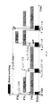
  • FIG. 3 depicts a Gantt chart for the schedule of wafer revisiting process (PM2, PM3) 2 ;
  • FIG. 4 depicts a Gantt chart of sequence A 2 23 A 01 A 12 A 30 A 1 23 A 32 with ⁇ 2 ⁇ 3 ;
  • FIG. 5 depicts a wafer sojourn time at different steps in different cases
  • FIG. 6 depicts a Gantt chart of sequence A 2 23 A 12 A 01 A 30 A 1 23 A 32 with ⁇ 2 ⁇ 3 ;
  • FIG. 7 depicts a Gantt chart of sequence A 2 23 A 12 A 30 A 1 23 A 01 A 32 with ⁇ 2 ⁇ 3 ;
  • FIG. 8 depicts a Gantt chart of sequence A 2 23 A 12 A 30 A 1 23 A 32 A 01 with ⁇ 2 ⁇ 3 ;
  • FIG. 9 depicts a Gantt chart of sequence A 2 23 A 12 A 01 A 30 A 1 23 A 32 with ⁇ 2 > ⁇ 3 ;
  • FIG. 10 depicts a Gantt chart of sequence A 2 23 A 12 A 30 A 01 A 1 23 A 32 with ⁇ 2 > ⁇ 3 ;
  • FIG. 11 depicts a Gantt chart of sequence A 2 23 A 12 A 30 A 1 23 A 01 A 32 with ⁇ 2 > ⁇ 3 ;
  • FIG. 12 depicts a Gantt chart of sequence A 2 23 A 12 A 30 A 1 23 A 32 A 01 with ⁇ 2 > ⁇ 3 ;
  • FIG. 13 depicts a Gantt chart of sequence A 2 23 A 30 A 12 A 01 A 1 23 A 32 ;
  • FIG. 14 depicts a Gantt chart of sequence A 2 23 A 12 A 01 A 30 A 1 23 A 32 .
  • Section A briefly introduces the ALD process and presents the robot task sequencing strategies. Based on them, schedulability conditions and scheduling algorithms are derived in Section B. Illustrative examples are used to show the obtained results in Section C.
  • ALD controls the deposition film thickness by adjusting the number of repeating times such that a mono-atomic layer precision can be obtained. Furthermore, it uses much lower processing temperature, i.e., 100° C.-400° C., rather than 550° C.-800° C. for chemical vapor deposition. Hence, ALD is increasingly used in the semiconductor industry.
  • a wafer visits Step 1 first, then Step 2 and followed by Step 3 . After that, it goes back to Step 2 and then Step 3 again and this process is performed for a total of k( ⁇ 2) times, where k is decided by a process plan.
  • multiple PMs may be configured for some steps to balance the workload among the steps.
  • the same processing environment is required as the wafer visits the prior step.
  • An embodiment of the present invention focuses on the ALD process with one PM being configured for each step.
  • PM1-PM3 be the PMs for Steps 1 - 3 , respectively.
  • the wafer flow pattern of an ALD process can be denoted as (PM1, (PM2, PM3) k ) with (PM2, PM3) k being a k-revisiting process.
  • PM1, (PM2, PM3) k being a k-revisiting process.
  • PM1, (PM2, PM3) 2 the wafer flow pattern is (PM1, (PM2, PM3) 2 ).
  • the loadlocks in a cluster tool can be treated as a processing step, as denoted by PM 0 .
  • the robot tasks include: unloading a processed wafer from a PM, moving from one PM to another with a wafer, loading a wafer into a PM for processing, moving from one PM to another without a wafer, and waiting.
  • the key to schedule a cluster tool is to schedule its robot tasks.
  • the temporal aspect for each robot activity is described as follows.
  • the time taken for robot tasks u i and l i is identical and denoted by ⁇ ; and the time taken for m ij except m 23 , i,j ⁇ 3 , m 1 23 , and m 2 23 is also same and denoted by ⁇ .
  • Let ⁇ i,j , i,j ⁇ 3 , except ⁇ 23 denote the time taken for the robot's waiting before unloading a wafer from PM i to move to PM j and, ⁇ 1 23 and ⁇ 2 23 the time for its waiting before unloading the same wafer from PM 2 to move to PM 3 for the first and second time, respectively.
  • ⁇ i ⁇ [ ⁇ i , ⁇ i + ⁇ i ] denote the wafer sojourn time in PM i .
  • the time duration for each activity is listed in Table I. In practice, as the robot task time is much shorter than wafer processing time, it is reasonable to assume that ⁇ i ⁇ 5( ⁇ + ⁇ ), i ⁇ N 3 .
  • a ij u i ⁇ m ij ⁇ l j and it is denoted as A ij ⁇ m ii ⁇ to indicate that m ii takes no time.
  • a 1 23 and A 2 23 are defined in a similar way. With them, one can describe a schedule by presenting the robot task sequence with no robot waiting being taken into consideration.
  • the optimal one-wafer cyclic schedule for (PM2, PM3) 2 is deterministic and unique and such a schedule can be described as A 2 23 A 12 A 30 A 1 23 A 32 .
  • W d (q) in PM i , d ⁇ 1, 2, 3, . . . ⁇ , q ⁇ N 2 , and i ⁇ N 3 denote the d-th wafer being processed in PM i for the q-th time.
  • the Gantt chart for the optimal one-wafer cyclic schedule of wafer revisiting process (PM2, PM3) 2 is illustrated in FIG. 3 . In FIG.
  • a 12 (2 ⁇ +2 ⁇ ) means that A 12 is performed and it takes 2 ⁇ +2 ⁇ time units.
  • the meaning of “A 1 23 (2 ⁇ +2 ⁇ )”, “A 32 (2 ⁇ + ⁇ )”, “A 2 23 (2 ⁇ + ⁇ )”, and “A 30 ⁇ m 33 ⁇ (2 ⁇ + ⁇ )” is similar. From FIG. 3 , one can observe that after A 12 (2 ⁇ +2 ⁇ ) is performed, the robot comes to PM 3 by performing m 23 immediately, and the time taken by A 12 together with m 23 is 2 ⁇ +3 ⁇ . As 2 ⁇ +3 ⁇ 3 , when W 1 (2) is processed in PM 3 , the robot is already at Step 3 . In other words, at time T 1 , m 23 in A 30 has been already performed.
  • the task performed is A 30 ⁇ m 33 ⁇ with 2 ⁇ + ⁇ time units being taken.
  • be the cycle time of the whole system.
  • T 1 be the time instant when a wafer is just loaded into a PM
  • T u be the time instant when the robot begins to unload a wafer from a PM.
  • the wafer residency time constraints are satisfied for both of them.
  • This case can be illustrated by the time taken for processing the wafers in a PM shown in FIG. 5 .
  • ⁇ d (q) in PM i , d, q ⁇ N 2 , and i ⁇ N 3 denote the sojourn time of the d-th wafer visiting PM i for the q-th time.
  • ⁇ d (q) ⁇ [ ⁇ i , ⁇ i + ⁇ i ] should hold. It follows from FIG. 5 that it is true for every step and every case. Therefore, for all cases, the wafer residency time constraints are satisfied.
  • a schedule can be obtained as shown in FIG. 8 .
  • W 3 (1) W 2 (1) that are processed in PM 1 and PM 2 , respectively.
  • W 3 (1) is unloaded at time instant ⁇ + ⁇ , one presents the following algorithm to schedule the system.
  • ⁇ ij 's are set as follows to obtain a one-wafer cyclic schedule if it exists.
  • a schedule can be obtained as shown in FIG. 11 .
  • a schedule can be obtained as depicted in FIG. 12 .
  • the wafer residency time constraints can be violated for only W 3 (1) being processed in PM 1 .
  • the following algorithm is used to set the robot waiting time.
  • ⁇ ij 's are set as follows to obtain a one-wafer cyclic schedule if it exists.
  • Theorem 9 Assume that: 1) the cycle time of the system is ⁇ > ⁇ and ⁇ 1 ⁇ 6 ⁇ +3 ⁇ +2( ⁇ 2 + ⁇ 3 ), 2) robot scheduling strategy A 2 23 A 30 A 12 A 01 A 1 23 A 32 is applied, and 3) the robot waiting time is set by Algorithm 9. Then, the obtained one-wafer cyclic schedule is feasible.
  • ⁇ m n must fall within [0, ⁇ m ].
  • ⁇ m n cannot be decided independently and a method is necessary to do so.
  • Algorithm 10 If ⁇ > ⁇ and robot scheduling strategy A 2 23 A 12 A 01 A 30 A 1 23 A 32 is applied, ⁇ ij 's are set as follows to obtain a one-wafer cyclic schedule if it exists.
  • Theorem 10 Assume that: 1) the cycle time of the system is ⁇ > ⁇ , 2) robot scheduling strategy A 2 23 A 12 A 01 A 30 A 1 23 A 32 is applied, and 3) the robot waiting time is set by Algorithm 10. Then, the obtained one-wafer cyclic schedule is feasible.
  • Theorem 11 A schedule obtained by Algorithms 1-10 is optimal in terms of cycle time.
  • the wafer flow pattern is (PM 1 , (PM 2 , PM 3 ) 2 ).
  • strategy A 2 23 A 12 A 30 A 1 23 A 32 A 01 is applied, it results in a schedule such that ⁇ > ⁇ .
  • Algorithm 4 is excluded.
  • ⁇ 01 0
  • the embodiments disclosed herein may be implemented using general purpose or specialized computing devices, computer processors, or electronic circuitries including but not limited to digital signal processors (DSP), application specific integrated circuits (ASIC), field programmable gate arrays (FPGA), and other programmable logic devices configured or programmed according to the teachings of the present disclosure.
  • DSP digital signal processors
  • ASIC application specific integrated circuits
  • FPGA field programmable gate arrays
  • Computer instructions or software codes running in the general purpose or specialized computing devices, computer processors, or programmable logic devices can readily be prepared by practitioners skilled in the software or electronic art based on the teachings of the present disclosure.
  • the present invention includes computer storage media having computer instructions or software codes stored therein which can be used to program computers or microprocessors to perform any of the processes of the present invention.
  • the storage media can include, but is not limited to, floppy disks, optical discs, Blu-ray Disc, DVD, CD-ROMs, and magneto-optical disks, ROMs, RAMs, flash memory devices, or any type of media or devices suitable for storing instructions, codes, and/or data.

Landscapes

  • Engineering & Computer Science (AREA)
  • Physics & Mathematics (AREA)
  • General Engineering & Computer Science (AREA)
  • General Physics & Mathematics (AREA)
  • Automation & Control Theory (AREA)
  • Quality & Reliability (AREA)
  • Manufacturing & Machinery (AREA)
  • Theoretical Computer Science (AREA)
  • Robotics (AREA)
  • Mechanical Engineering (AREA)
  • Computer Hardware Design (AREA)
  • Evolutionary Computation (AREA)
  • Geometry (AREA)
  • Container, Conveyance, Adherence, Positioning, Of Wafer (AREA)
  • General Factory Administration (AREA)

Abstract

In semiconductor manufacturing, there are wafer fabrication processes in cluster tools that need a wafer to visit some processing steps for more than once, leading to a revisiting process. Also, wafers may be subject to wafer residency time constraints. By considering atomic layer deposition (ALD) as a typical wafer revisiting process, this invention studies the challenging scheduling problem of single-arm cluster tools for the ALD process with wafer residency time constraints. By recognizing that the key to this problem is to schedule the robot tasks, the present invention presents different robot task sequencing strategies. With these strategies for different cases, the present invention performs the schedulability analysis and derives the schedulability conditions for such tools for the first time. If schedulable, the present invention proposes scheduling algorithms to obtain an optimal schedule efficiently. Illustrative examples are given to show the application of the proposed concepts and approach.

Description

CLAIM FOR DOMESTIC PRIORITY
This application claims priority under 35 U.S.C. §119 to the U.S. Provisional Patent Application No. 62/102,112 filed Jan. 12, 2015, the disclosure of which is incorporated herein by reference in its entirety.
COPYRIGHT NOTICE
A portion of the disclosure of this patent document contains material, which is subject to copyright protection. The copyright owner has no objection to the facsimile reproduction by anyone of the patent document or the patent disclosure, as it appears in the Patent and Trademark Office patent file or records, but otherwise reserves all copyright rights whatsoever.
FIELD OF THE INVENTION
The present invention relates to a method for scheduling single-arm cluster tools. More particularly, the present invention relates to a method for scheduling single-arm cluster tools with wafer revisiting and residency time constraints.
BACKGROUND
The following references are cited in the specification. Disclosures of these references are incorporated herein by reference in their entirety.
List of References:
  • N. Brauner, “Identical part production in cyclic robotic cells: Concepts, overview and open questions,” Discrete Appl. Math., vol. 156, no. 13, pp. 2480-2492, 2008.
  • W. K. Chan, J. G. Yi, and S. W. Ding, “Optimal Scheduling of Multi-cluster Tools with Constant Robot Moving Times, Part I: Two-Cluster Analysis,” IEEE Transactions on Automation Science and Engineering, vol. 8, no. 1, pp. 5-16, 2011a.
  • W. K. Chan, J. G. Yi, S. W. Ding, and D. Z. Song, “Optimal Scheduling of Multi-cluster Tools with Constant Robot Moving Times, Part II: Tree-Like Topology Configurations,” IEEE Transactions on Automation Science and Engineering, vol. 8, no. 1, pp. 17-28, 2011b.
  • Y. Crama, V. Kats, J. van de Klundert, and E. Levner, “Cyclic scheduling in robotic flowshops,” Ann. Oper. Res.: Math. Ind. Syst., vol. 96, no. 1-4, pp. 97-124, 2000.
  • Y. Crama and J. van de Klundert, “Cyclic scheduling of identical parts in a robotic cell,” Oper. Res., vol. 45, no. 6, pp. 952-965, 1997.
  • M. Dawande, N. Geismar, M. Pinedo, and C. Sriskandarajah, “Throughput optimization in dual-gripper interval robotic cells,” IIE Trans., vol. 42, no. 1, pp. 1-15, January 2010.
  • M. Dawande, H. N. Geismar, S. P. Sethi, and C. Sriskandarajah, Throughput Optimization in Robotic Cells. New York: Springer, 2007.
  • M. Dawande, C. Sriskandarajah, and C. S. Sethi, “On throughput maximization in constant travel-time robotic cells,” Manuf. Serv. Oper. Manage., vol. 4, no. 4, pp. 296-312, 2002.
  • H. N. Geismar, L. M. A. Chan, M. Dawande, and C. Sriskandarajah, “Approximations to optimal k-unit cycles for single- and dual-gripper robotic cells,” Prod. Oper. Manage H. N. Geismar, L. M. A. Chan, M. Dawande, and C. Sriskandarajah, “Approximations to optimal k-unit cycles for single- and dual-gripper robotic cells,” Prod. Oper. Manage., vol. 17, no. 5, pp. 551-563, 2008.
  • H. N. Geismar, M. Dawande, and C. Sriskandarajah, “Throughput optimization in constant travel-time dual-gripper robotic cells with parallel machines,” Prod. Oper. Manage., vol. 15, no. 2, pp. 311-328, 2006.
  • J.-H. Kim, T.-E. Lee, H.-Y. Lee, and D.-B. Park, Scheduling analysis of timed-constrained dual-armed cluster tools, IEEE Transactions on Semiconductor Manufacturing, vol. 16, no. 3, 521-534, 2003.
  • T.-E. Lee and S.-H. Park, “An extended event graph with negative places and tokens for timed window constraints,” IEEE Transactions on Automation Science and Engineering, vol. 2, no. 4, 319-332, 2005.
  • H.-Y. Lee and T.-E. Lee. Scheduling single-arm cluster tools with reentrant wafer flows. IEEE transactions on Semiconductor Manufacturing, vol.19, no.2, 226-240, 2006.
  • T.-E. Lee, H.-Y. Lee, and Y.-H. Shin, Workload balancing and scheduling of a single-armed cluster tool, in Proceedings of the 5th APIEMS Conference, Gold Coast, Australia, 1-15, 2004.
  • M.-J. Lopez and S.-C. Wood, Systems of multiple cluster tools—configuration, reliability, and performance, IEEE Transactions on Semiconductor Manufacturing, vol. 16, no. 2, 170-178, 2003.
  • M., Pinedo, Scheduling: Theory, Algorithms, and Systems, Prentice Hall, Englewood Cliffs, N.J., 1995.
  • T. L. Perkinson, R. S. Gyurcsik, and P. K. MacLarty, “Single-wafer cluster tool performance: An analysis of the effects of redundant chambers and revisitations sequences on throughput,” IEEE Transactions on Semiconductor Manufacturing, vol. 9, no. 3, 384-400, 1996.
  • T. L. Perkinson, P. K. MacLarty, R. S. Gyurcsik, and R. K. Cavin, III, “Single-wafer cluster tool performance: An analysis of throughput,” IEEE Transactions on Semiconductor Manufacturing, vol. 7, no. 3, 369-373, 1994.
  • Y. Qiao, N. Q. Wu, and M. C. Zhou, A Petri net-based novel scheduling approach and its cycle time analysis for dual-arm cluster tools with wafer revisiting, IEEE Transactions on Semiconductor manufacturing, vol. 26, no. 1, 100-110, 2013.
  • Y. Qiao, N. Q. Wu, and M. C. Zhou, Scheduling of dual-arm cluster tools with wafer revisiting and residency time constraints, IEEE Transactions on Industrial Informatics, vol. 10, no. 1, 286-300, 2014a.
  • Y. Qiao, N. Q. Wu, and M. C. Zhou, Schedulability and scheduling analysis of dual-arm cluster tools with wafer revisiting and residency time constraints based on a novel schedule, IEEE Transactions on Systems, Man, & Cybernetics: Systems, in press, 2014b.
  • S. Sechi, J. Sidney, and C. Sriskandarajah, “Scheduling in dual-gripper robotic cells for productivity gains,” IEEE Trans. Robot. Autom., vol.17, no. 3, pp. 324-341, 2001.
  • S. Sechi, C. Sriskandarajah, G. Sorger, J. Blazewicz, and W. Kubiak, “Sequencing of parts and robot moves in a robotic cell,” Int. J. Flexible Manuf. Syst., vol. 4, no. 3-4, pp. 331-358, 1992.
  • S. Venkatesh, R. Davenport, P. Foxhoven, and J. Nulman, “A steady state throughput analysis of cluster tools: Dual-blade versus single-blade robots”, IEEE Trans. Semiconduct. Manuf ., vol.10, no. 4, pp. 418-424, 1997.
N. Q. Wu, C. B. Chu, F. Chu, and M. C. Zhou, “A Petri net method for schedulability and scheduling problems in single-arm cluster tools with wafer residency time constraints,” IEEE Transactions on Semiconductor Manufacturing, vol. 21, no. 2, pp. 224-237, 2008.
  • N. Q. Wu, F. Chu, C. Chu, and M. Zhou, “Petri Net-Based Scheduling of Single-Arm Cluster Tools With Reentrant Atomic Layer Deposition Processes,” IEEE Transactions on Automation Science and Engineering, vol. 8, no. 1, pp. 42-55, 2011.
  • N. Q. Wu, F. Chu, C. B. Chu, and M. C. Zhou, “Petri net modeling and cycle time analysis of dual-arm cluster tools with wafer revisiting,” IEEE Transactions on Systems, Man, & Cybernetics: Systems, vol. 43, no. 1, pp. 196-207, 2013a.
  • N. Q. Wu and M. Zhou, “Analysis of wafer sojourn time in dual-arm cluster tools with residency time constraint and activity time variation,” IEEE Transactions on Semiconductor Manufacturing, vol. 23, no. 1, pp. 53-64, 2010a.
  • N. Q. Wu and M. C. Zhou, “A closed-form solution for schedulability and optimal scheduling of dual-arm cluster tools based on steady schedule analysis,” IEEE Transactions on Automation Science and Engineering, vol. 7, no. 2, 303-315, 2010b.
  • N. Q. Wu and M. C. Zhou, Colored timed Petri nets for modeling and analysis of cluster tools, Asian Journal of Control, vol. 12, no. 3, 253-266, 2010c.
  • N. Q. Wu and M. C. Zhou, “Modeling, analysis and control of dual-arm cluster tools with residency time constraint and activity time variation based on Petri nets,” IEEE Transactions on Automation Science and Engineering, vol. 9, no. 2, 446-454, 2012a.
  • N. Q. Wu and M. C. Zhou, “Schedulability analysis and optimal scheduling of dual-arm cluster tools with residency time constraint and activity time variation,” IEEE Transactions on Automation Science and Engineering, vol. 9, no. 1, 203-209, 2012b.
  • N. Q. Wu, M. C. Zhou, F. Chu, and C. B. Chu, A Petri-net-based scheduling strategy for dual-arm cluster tools with wafer revisiting, IEEE Transactions on Systems, Man, & Cybernetics: Systems, vol. 43, no. 5, 1182-1194, 2013b.
  • W. M. Zuberek, “Timed Petri nets in modeling and analysis of cluster tools,” IEEE Transactions on Robotics Automation, vol. 17, no. 5, pp. 562-575, October 2001.
  • W. M. Zuberek, “Cluster tools with chamber revisiting—modeling and analysis using timed Petri nets”, IEEE Transactions on Semiconductor Manufacturing, vol. 17, no. 3, 333-344, 2004.
With a single-wafer processing technology, cluster tools are widely used for wafer fabrication in semiconductor manufacturing. A typical cluster tool has several process modules (PMs), two loadlocks, and a wafer handling robot with a radical layout as shown in FIG. 1. Equipped with one or two arms for the robot, the corresponding tool is called a single or dual-arm cluster tool. Cassettes with lots of raw wafers are loaded into or unloaded from a cluster tool through the loadlocks. A wafer is unloaded from the loadlock by the robot and delivered to one or more PMs for processing in a pre-specified order decided by a recipe. Often, the wafers in a cassette have an identical recipe. A wafer should stay in a PM for a minimum time to be processed. After all operations are completed, it returns to the cassette from which it comes [Wu et al., 2010b]. When all the wafers in a cassette are processed, the cassette is unloaded from the loadlock such that another cassette can be loaded. In this way, with two loadlocks, a cluster tool can operate consecutively without interruption.
Cluster tools are a kind of robotic cells and a robotic cell is a flow-shop with blocking [Pinedo, 1995]. Extensive work has been done for the operation of a robotic cell [Brauner, 2008; Crama et al., 1997 and 2000; Dawande et al., 2002, 2007 and 2009; Geismar et al., 2006 and 2008; Sechi et al., 1992 and 2001]. They mainly focus on a flow-shop operation mode with one part type to be processed and a processed part can stay at a machine for an unlimited time. A cyclic schedule is called a k-unit schedule if exactly k parts are produced during every period [Sechi et al., 1992]. When k=1, it is a one-unit cyclic schedule. Owing to its easy implementation, one-unit cyclic schedule is the most desired in practice assuming that all the schedules achieve the same maximum throughput.
To effectively operate a single-cluster tool, plenty of studies have been done [Venkatesh et al., 1997; Perkinson et al., 1994 and 1996; Zuberek, 2001; Wu et al., 2011 and 2013; and Wu and Zhou, 2010a, 2012a, and 2012b]. They show that a cluster tool mostly operates under a steady state. If the robot is the bottleneck and the robot task time decides the cycle time of a tool, the tool operates in a transport-bound region. Contrarily, if the wafer processing time dominates the process and decides the cycle time, it operates in a process-bound region. In practice, the robot task time is much shorter than the wafer processing time [Lee et al., 2004; Lopez and Wood, 2003]. Thus, a single-arm cluster tool is mostly process-bound and a backward scheduling strategy is shown to be optimal [Lee et al., 2004; Lopez and Wood, 2003].
Some wafer fabrication processes impose strict wafer residency time constraints in a PM, which requires that a processed wafer be removed from the PM within a limited time, otherwise it suffers from serious quality problem [Kim et al., 2003; Lee and Park, 2005]. With such constraints, the scheduling problem of cluster tools becomes very complicated and challenging. Methods are developed in [Kim et al., 2003; Lee and Park, 2005] to schedule dual-arm cluster tools with wafer residency time constraints for cyclic scheduling. With Petri net models and robot waiting concept, much more efficient techniques are presented in [Wu et al., 2008; and Wu and Zhou, 2010a] for scheduling both single and dual-arm cluster tools.
In wafer fabrication, a wafer may need to visit some processing steps several times, leading to a revisiting process. Atomic layer deposition (ALD) is a typical revisiting process in the semiconductor manufacturing [Lee, et al., 2006]. With wafer revisiting, it is challenging to schedule a cluster tool. All the aforementioned studies are conducted on cluster tools for non-revisiting processes. To explore the potential in operating a cluster tool with wafer revisiting, methods are presented for performance evaluation by using Petri net models in [Zuberek, et al., 2004; and Wu and Zhou, 2010c] without providing a scheduling technique. Lee, et al. [2006] study the scheduling problem of single-arm cluster tools with wafer revisiting for the first time. In their work, based on a Petri net model, the problem is formulated as a mixed integer programming such that an optimal schedule can be found. This problem is further investigated in [Wu, et al., 2011] for the ALD process by using Petri net model and analytical expressions are derived to find the optimal schedule. For dual-arm cluster tools with wafer revisiting, based on a Petri net model, Wu et al., [2013a] find that, by using a swap strategy, the system may never enter a steady state and analytical expressions are presented to correctly calculate the cycle time. Based on this finding, effective methods are developed to schedule such dual-arm cluster tools in [Wu et al., 2013b; and Qiao et al., 2013].
With both wafer residency time constraints and revisiting, the scheduling problem of cluster tools is very complicated. Based on the scheduling strategy proposed in [Qiao et al., 2013], effective techniques are developed to schedule dual-arm cluster tools for the ALD process with wafer residency time constraints for different situations in [Qiao et al., 2014a and 2014b]. Up to now, there is no research report on scheduling single-cluster tools with both wafer residency time constraints and wafer revisiting. Notice that, with wafer revisiting, it is more difficult to balance the workloads among the steps for a single-arm cluster tool than for a dual-arm cluster tool, thereby, leading to a more difficult problem to schedule a single-arm tool than a dual-arm one.
There is a need in the art for a method to obtain a schedule when wafer revisiting process and residency time constraints are taken into consideration.
SUMMARY OF THE INVENTION
An aspect of the present invention is to provide a computer implemented method for scheduling a single-arm cluster tool with wafer revisiting process and residency time constraints.
According to an embodiment of the present claimed invention, a computer implemented method for scheduling a single-arm cluster tool with wafer revisiting process and residency time constraints comprises: obtaining, by a processor, a wafer processing time, a wafer residency time, a robot task time for loading/unloading a wafer, and a robot task time for robot's moving; determining, by a processor, a cycle time for the wafer revisiting process based on the wafer processing time, the robot task time for loading/unloading the wafer, and the robot task time for robot's moving; determining, by a processor, a cycle time of system based on the wafer processing time, the robot task time for loading/unloading the wafer, and the robot task time for robot's moving; determining, by a processor, a case of an algorithm from a plurality of defined cases of algorithms based on the wafer processing time, the determined cycle time for the wafer revisiting process, and the determined cycle time of system; determining, by a processor, a robot scheduling strategy based on the determined case of the algorithm, wherein the robot scheduling strategy comprises a plurality of basic activity sequences; determining, by a processor, a robot waiting time based on the wafer residency time and the determined case of the algorithm; and generating, by a processor, a schedule based on the determined robot scheduling strategy and the determined robot waiting time.
The present invention makes the following contributions: 1) schedulability conditions under which a feasible cyclic schedule exists are proposed; and 2) If schedulable, closed-form algorithms are developed to find the optimal schedule.
With wafer revisiting and wafer residency time constraints, it is highly challenging to schedule a cluster tool. For an ALD process, the present invention solves such a scheduling problem for single-arm cluster tools with wafer flow pattern (PM1, (PM2, PM3)2). Based on a prior work [Wu, et al., 2011], different strategies for scheduling the robot task sequence are proposed and analyzed. Then, for different cases, schedulability analysis is conducted and schedulability conditions are established. If schedulable, scheduling algorithms are proposed such that a feasible and optimal schedule is swiftly found. Thus, the method of the present invention represents a significant advancement in this research field.
The results obtained are for ALD process with the wafer flow pattern (PM1, (PM2, PM3)2), which looks very simple but its optimal scheduling task is actually much more complicated than one might think or in comparison with a non-revisiting process.
BRIEF DESCRIPTION OF THE DRAWINGS
FIG. 1 shows cluster tools: (a) single-arm tool, and (b) dual-arm tool;
FIG. 2 illustrates an ALD process (k>1);
FIG. 3 depicts a Gantt chart for the schedule of wafer revisiting process (PM2, PM3)2;
FIG. 4 depicts a Gantt chart of sequence A2 23A01A12A30A1 23A32 with α2≦α3;
FIG. 5 depicts a wafer sojourn time at different steps in different cases;
FIG. 6 depicts a Gantt chart of sequence A2 23A12A01A30A1 23A32 with α2≦α3;
FIG. 7 depicts a Gantt chart of sequence A2 23A12A30A1 23A01A32 with α2≦α3;
FIG. 8 depicts a Gantt chart of sequence A2 23A12A30A1 23A32A01 with α2≦α3;
FIG. 9 depicts a Gantt chart of sequence A2 23A12A01A30A1 23A32 with α23;
FIG. 10 depicts a Gantt chart of sequence A2 23A12A30A01A1 23A32 with α23;
FIG. 11 depicts a Gantt chart of sequence A2 23A12A30A1 23A01A32 with α23;
FIG. 12 depicts a Gantt chart of sequence A2 23A12A30A1 23A32A01 with α23;
FIG. 13 depicts a Gantt chart of sequence A2 23A30A12A01A1 23A32; and
FIG. 14 depicts a Gantt chart of sequence A2 23A12A01A30A1 23A32.
DETAILED DESCRIPTION
In the following description, a computer implemented method for scheduling single-arm cluster tools with wafer revisiting process and residency time constraints is set forth as preferred examples. It will be apparent to those skilled in the art that modifications, including additions and/or substitutions maybe made without departing from the scope and spirit of the invention. Specific details may be omitted so as not to obscure the invention; however, the disclosure is written to enable one skilled in the art to practice the teachings herein without undue experimentation.
Accordingly, Section A briefly introduces the ALD process and presents the robot task sequencing strategies. Based on them, schedulability conditions and scheduling algorithms are derived in Section B. Illustrative examples are used to show the obtained results in Section C.
A. Fabrication Process and Scheduling Strategies
A.1 A. Atomic Layer Deposition Process
As a typical wafer fabrication process in semiconductor manufacturing, ALD controls the deposition film thickness by adjusting the number of repeating times such that a mono-atomic layer precision can be obtained. Furthermore, it uses much lower processing temperature, i.e., 100° C.-400° C., rather than 550° C.-800° C. for chemical vapor deposition. Hence, ALD is increasingly used in the semiconductor industry.
In an ALD process, there are three steps as shown in FIG. 2, a wafer visits Step 1 first, then Step 2 and followed by Step 3. After that, it goes back to Step 2 and then Step 3 again and this process is performed for a total of k(≧2) times, where k is decided by a process plan. In a cluster tool, multiple PMs may be configured for some steps to balance the workload among the steps. However, for a revisiting process, when a wafer revisits a processing step, the same processing environment is required as the wafer visits the prior step. With such a requirement, for the ALD process, often, only one PM is configured for a step to guarantee uniformity. An embodiment of the present invention focuses on the ALD process with one PM being configured for each step. Let PM1-PM3 be the PMs for Steps 1-3, respectively. Then, the wafer flow pattern of an ALD process can be denoted as (PM1, (PM2, PM3)k) with (PM2, PM3)k being a k-revisiting process. For the simplicity of presentation, one considers the case of k=2 only. Nevertheless, the obtained results for k=2 can be extended to cases of k>2. With k=2, the wafer flow pattern is (PM1, (PM2, PM3)2).
A.2 Activity Description
The loadlocks in a cluster tool can be treated as a processing step, as denoted by PM0. In operating a cluster tool, the robot tasks include: unloading a processed wafer from a PM, moving from one PM to another with a wafer, loading a wafer into a PM for processing, moving from one PM to another without a wafer, and waiting. Given the status of a cluster tool and the wafer processing information, the key to schedule a cluster tool is to schedule its robot tasks.
TABLE 1
THE TIME DURATIONS ASSOCIATED WITH EACH ACTIVITY
Symbol Action Time
ui/li The robot unloads/loads a wafer from/into Step i , i ε λ
Ω3
mij The robot's moving from Steps i to j with or without μ
carrying a wafer, i, j ε Ω3
m1 23 and The robot's moving from Step 2 to 3 with the same μ
m2 23 wafer hold for the first and second time, respectively
Therefore, for scheduling of a single-arm cluster tool, the system is described as follows. Let ui and li denote the robot unloading and loading a wafer from and into PMi, i∈Ω3={0, 1, 2, 3}, respectively. Further, let mij, i,j∈Ω3, except m23, denote the robot's moving from Steps i to j, and m1 23 and m2 23 denote its moving from Step 2 to 3 holding the same wafer for the first and second time, respectively.
Correspondingly, the temporal aspect for each robot activity is described as follows. The time taken for robot tasks ui and li is identical and denoted by λ; and the time taken for mij except m23, i,j∈Ω3, m1 23, and m2 23 is also same and denoted by μ. Let ωi,j, i,j∈Ω3, except ω23, denote the time taken for the robot's waiting before unloading a wafer from PMi to move to PMj and, ω1 23 and ω2 23 the time for its waiting before unloading the same wafer from PM2 to move to PM3 for the first and second time, respectively.
Apart from the robot tasks, the wafer processing in a PM also takes time. Note that there is no processing requirement in the loadlocks. Thus, one uses αi to denote the time taken for processing a wafer in PMi, i∈N3={1, 2, 3}. With wafer residency constraints, a processed wafer should be unloaded from PMi within a limited time δi, which implies that a wafer can stay in PMi for a duration that lies in the interval [αi, αii] without suffering from a quality problem. Let τi∈[αi, αii] denote the wafer sojourn time in PMi. The time duration for each activity is listed in Table I. In practice, as the robot task time is much shorter than wafer processing time, it is reasonable to assume that αi≧5(μ+λ), i∈N3.
It is known that a single-arm cluster tool for the ALD process is deadlock-prone [Lee and Lee, 2006; and Wu, et al., 2011]. However, this problem can be solved by using the policy presented in [Wu, et al., 2011]. Then, for a single-arm cluster tool with wafer revisiting and residency time constraints, according to [Wu et al., 2008; and Wu and Zhou, 2010b], the following schedulability definition is presented.
Definition 1 [Wu et al., 2008; and Wu and Zhou, 2010b]: Given wafer sojourn time interval [αi, αii] for Step i, i∈N3, if there exists a schedule such that whenever ui is performed, αi≦τi≦αii holds, then, a single-arm cluster tool with wafer revisiting and residency time constraints is schedulable.
A.3 Scheduling Strategy
Following the idea in [Chan, et. al., 2011a and b], to simplify the presentation, one defines a basic activity sequence Aij=
Figure US09223307-20151229-P00001
mxi (without carrying a wafer)→ui→mijlj
Figure US09223307-20151229-P00002
, i,j∈Ω3, where mxi denotes that the robot can come to Step i from any Step x. Notice that x=i may hold, or the task before performing Aij is li. This means that, to perform Aij, the robot is already at Step i. In this case, Aij=
Figure US09223307-20151229-P00003
ui→mij→lj
Figure US09223307-20151229-P00004
and it is denoted as Aij\{mii} to indicate that mii takes no time. Also, A1 23 and A2 23 are defined in a similar way. With them, one can describe a schedule by presenting the robot task sequence with no robot waiting being taken into consideration.
According to Wu, et al. [2011], without wafer residency time constraints, the optimal one-wafer cyclic schedule for (PM2, PM3)2 is deterministic and unique and such a schedule can be described as A2 23A12A30A1 23A32. Let Wd(q) in PMi, d∈{1, 2, 3, . . . }, q∈N2, and i∈N3, denote the d-th wafer being processed in PMi for the q-th time. The Gantt chart for the optimal one-wafer cyclic schedule of wafer revisiting process (PM2, PM3)2 is illustrated in FIG. 3. In FIG. 3, “A12(2λ+2μ)” means that A12 is performed and it takes 2λ+2μ time units. The meaning of “A1 23(2λ+2μ)”, “A32(2λ+μ)”, “A2 23(2λ+μ)”, and “A30\{m33}(2λ+μ)” is similar. From FIG. 3, one can observe that after A12(2λ+2μ) is performed, the robot comes to PM3 by performing m23 immediately, and the time taken by A12 together with m23 is 2λ+3μ. As 2λ+3μ<α3, when W1(2) is processed in PM3, the robot is already at Step 3. In other words, at time T1, m23 in A30 has been already performed. Hence, during the time between T1 and T2, the task performed is A30\{m33} with 2λ+μ time units being taken. For this schedule, the cycle time for the revisiting process is ζ=Max {2λ+3μ, α2, α3}+(4λ+3μ)+(4λ+2μ+α23)=8λ+5μ+α23+Max{α2, α3}.
Let Θ be the cycle time of the whole system. One has Θ=ζ or Θ>ζ. If Θ=ζ, the robot activity sequence for the revisiting process (PM2, PM3)2 in the schedule for the entire system should be same as that in the optimal one-wafer cyclic schedule for (PM2, PM3)2, or it is A2 23A12A30A1 23A32. Then, to obtain a schedule for the entire system, the key is to decide when A01 should be performed while satisfying the wafer residency time constraints. There are totally five possible robot task sequences for the entire system, i.e., 1) A2 23A01A12A30A1 23A32; 2) A2 23A12A01A30A1 23A32; 3) A2 23A12A30A01A1 23A32; 4) A2 23A12A30A1 23A01A32; and 5) A2 23A12A30A1 23A32A01, leading to five different strategies. One needs to analyze them, respectively.
For Case 1): A2 23A01A12A30A1 23A32, i.e., without robot waiting, the robot activity sequence is σ1=
Figure US09223307-20151229-P00001
unloading a wafer from PM2 (λ)→moving to PM3 (μ)→loading a wafer into PM3 (λ)→moving to PM0 (μ)→unloading a wafer from PM0 (λ)→moving to PM1 (μ)→loading a wafer into PM1 (λ)→unloading a wafer from PM1 (λ)→moving to PM2 (μ)→loading a wafer into PM2 (λ)→moving to PM3 (μ)→unloading a wafer from PM3 (λ)→moving to PM0 (μ)→loading a wafer into PM0 (λ)→moving to PM2 (μ)→unloading a wafer from PM2 (λ)→moving to PM3 (μ)→loading a wafer into PM3 (λ)→unloading a wafer from PM3 (λ)→moving to PM2 (μ)→loading a wafer into PM2 (λ)
Figure US09223307-20151229-P00002
. Therefore, in this case, the robot cycle time without waiting for the entire system is
ψ11=12λ+9μ  (1)
For Case 2): A2 23A12A01A30A1 23A32, the robot activity sequence is σ2=
Figure US09223307-20151229-P00001
unloading a wafer from PM2 (λ)→moving to PM3 (μ)→loading a wafer into PM3 (λ)→moving to PM1 (μ)→unloading a wafer from PM1 (λ)→moving to PM2 (μ)→loading a wafer into PM2 (λ)→moving to PM0 (μ)→unloading a wafer from PM0 (λ)→moving to PM1 (μ)→loading a wafer into PM1 (λ)→moving to PM3 (μ)→unloading a wafer from PM3 (λ)→moving to PM0 (μ)→loading a wafer into PM0 (λ)→moving to PM2 (μ)→unloading a wafer from PM2 (λ)→moving to PM3 (μ)→loading a wafer into PM3 (λ)→unloading a wafer from PM3 (λ)→moving to PM2 (μ)→loading a wafer into PM2 (λ)
Figure US09223307-20151229-P00002
. Hence, one has
ψ21=12λ+10μ  (2)
Similarly, for Cases 3) A2 23A12A30A01A1 23A32, 4) A2 23A12A30A1 23A01A32, and 5) A2 23A12A30A1 23A32A01, one has
ψ31=12λ+9μ  (3)
ψ41=12λ+11μ  (4)
ψ51=12λ+11μ  (5)
If Θ>ζ, it implies that the wafer processing time in PM1 decides the cycle time of the system. In this case, to obtain an optimal schedule, after performing A12, one should perform A01 immediately to keep PM1, the bottleneck of the system, working. Furthermore, according to the fabrication requirements, A12 and A30 should be performed before A1 23, and A1 23 before A32. Therefore, there are two different strategies only, i.e., Case 6): A2 23A30A12A01A1 23A32 and Case 7): A2 23A12A01A30A1 23A32.
For Case 6, one has σ6=
Figure US09223307-20151229-P00001
unloading a wafer from PM2 (λ)→moving to PM3 (μ)→loading a wafer into PM3 (λ)→unloading a wafer from PM3 (λ)→moving to PM0 (μ)→loading a wafer into PM0 (λ)→moving to PM1 (μ)→unloading a wafer from PM1 (λ)→moving to PM2 (μ)→loading a wafer into PM2 (λ)→moving to PM0 (μ)→unloading a wafer from PM0 (λ)→moving to PM1 (μ)→loading a wafer into PM1 (λ)→moving to PM2 (μ)→unloading a wafer from PM2 (λ)→moving to PM3 (μ)→loading a wafer into PM3 (λ)→unloading a wafer from PM3 (λ)→moving to PM2 (μ)→loading a wafer into PM2 (λ)
Figure US09223307-20151229-P00002
. Thus, the robot cycle time without waiting is
ψ61=12λ+9μ  (6)
For Case 7, it is same as Case 2, and the robot cycle time without waiting is
ψ71=12λ+10μ  (7)
With the above analysis, one discusses the schedulability and scheduling method next by examining the above cases for scheduling the robot task sequence.
B. Schedulability and Scheduling
In this section, based on Θ=ζ or Θ>ζ, one studies the schedulability and scheduling problem by examining each of the above robot scheduling strategies. For any above given robot scheduling strategy, if a schedule exists, an algorithm is derived to find it by setting the robot waiting time simply.
A. Θ=ζand α2≦α3
With α2≦α3, one has ζ=8λ+5μ+α23+Max{α2, α3}=8λ+5μ+α2+2α3. If a schedule is obtained by robot task sequence A2 23A01A12A30A1 23A32 or Case 1, the Gantt chart can be shown in FIG. 4 where the highlighted path with red color is the critical one. This implies that, to obtain an optimal schedule, one should find no delay along this path. With this observation, the robot task sequence can be equivalently denoted as A01A12A30A1 23A32A2 23.
It follows from the Gantt chart in FIG. 4 that, to make Θ=ζ, 2λ+2μ+α1+2λ+μ+α2≦α3+(2λ+μ)+μ
Figure US09223307-20151229-P00005
α12+2λ+μ≦α3 must hold. Let ψi2, i∈N7, be the robot waiting time in a cycle. Then, for A2 23A01A12A30A1 23A32, one has ψ12=ζ−ψ11=(8λ+5μ+α2+2α3)−(12λ+9μ)=2α32−4λ−4μ. In this case, it follows from FIG. 4 that W1(2), W2(1), and W2(2) are unloaded immediately after being processed in PM3, PM3, and PM2, respectively. Thus, wafer residency time constraints may be violated for only W2(1) and W2(1) that are processed in PM1 and PM2, respectively. To obtain a feasible schedule if it exists, the key is to assign ψ12 into ωij's properly. To do so, one presents the following algorithm.
Algorithm 1: If Θ=ζ with α12+2λ+μ≦α3 and the robot task sequence is A2 23A01A12A30A1 23A32, ωij's are set as follows to obtain a one-wafer cyclic schedule if it exists.
i. Q=1.
ii. If α3≦α12+2λ+μ+δ1
    • 2.1. ω01=0, ω123−α2−2λ−μ, ω303−4λ−4μ−ω12, ω1 23=0, ω323, and ω2 232;
    • 2.2. Go to Step vi.
iii. If α3≦α12+2λ+μ+δ2
    • 3.1. ω01=0, ω121, ω303−4λ−4μ−ω12, ω1 23=0, ω323, and ω2 232;
    • 3.2. Go to Step vi.
iv. If α12+2λ+μ+δ13, α12+2λ+μ+δ23, and α12+2λ+μ+δ12≧α3
    • 4.1. ω01=0, ω1211, ω303−4λ−4μ−ω12, ω1 23=0, ω323, and ω2 232;
    • 4.2. Go to Step vi.
v. If α12+2λ+μ+δ123
    • 5.1. ω013−(α12+2λ+μ+δ12);
    • 5.2. If ω013−4λ−4μ−α1−δ1, Q=0 and go to Step vi;
    • 5.3. Otherwise, ω1211, ω303−4λ−4μ−ω12−ω01, ω1 23=0, ω323, and ω2 232;
    • 5.4. Go to Step vi.
vi. Return Q and end.
By Algorithm 1, α12+2λ+μ≦α3. Thus, for Case ii, with αi≧5(μ+λ), one has ω123−α2−2λ−μ≧α1>0, ω303−4λ−4μ−(α3−α2−2λ−μ)=α2−2λ−3μ>0. For Case iii, ω303−4λ−4μ−α1≧α2−2λ−3μ>0. For Case iv, ω303−4λ−4μ−(α11)>( α12+2λ+μ+δ1)−4λ−4μ−(α11)=α2−2λ−3μ>0. For Case v, if Q=1 is returned, 0<ω013−(α12+2λ+μ+δ12)≦α3−4λ−4μ−α1−δ1, leading to ω303−4λ−4μ−ω12−ω01≧0. Hence, any robot waiting time set by Algorithm 1 is non-negative if Q=1 is returned. Furthermore, for each case, one has ψ120112302 23321 23=2α32−4λ−4μ such that Θ=Θ=ψ1112. The following theorem presents the feasibility of the schedule obtained by Algorithm 1.
Theorem 1: Assume that: 1) the cycle time of the system is Θ=ζ with α12+2λ+μ≦α3, 2) the robot task sequence is A2 23A01A12A30A1 23A32, and 3) the robot waiting time is set by Algorithm 1 with Q=1 being returned. Then, the obtained one-wafer cyclic schedule is feasible.
Proof: One needs to show that the wafer residency time constraints are satisfied for only W2(1) and W2(1) that are processed in PM1 and PM2, respectively. Let τi denote the wafer sojourn time in PMi. It follows from FIG. 4 that, for Case ii and W2(1) in PM1, one has τ1121+[α3−(α12+2λ+μ)]. By assumption, 0≦α3−(α12+2λ+μ)≦δ1. Hence, one has α1≦τ1≦α11. To calculate τ2, let T1 be the time instant when a wafer is just loaded into a PM and Tu be the time instant when the robot begins to unload a wafer from a PM. For W2(1) in PM2, from FIG. 4, one has Tl=2λ+2μ+ω12+2λ+μ and Tu3+2λ+2μ, leading to τ2=Tu−Tl3+2λ+2μ−(2λ+2μ+ω12+2λ+μ)=α2. The wafer residency time constraints are satisfied for both of them. For Case iii, τ1121 and τ2=Tu−Tl3+2λ+2μ−(2λ+2μ+ω12+2λ+μ)=α3−α1−2λ−μ. Since α2≦α3−α1−2λ−μ≦α22, one has α2≦τ2≦α22. For Case iv, τ11211 and τ2=Tu−Tl3+2λ+2μ−(2λ+2μ+ω12+2λ+μ)=α3−α1−δ1−2λ−μ. Since (α12+2λ+μ+δ1)−α1−δ1−2λ−μ=α2≦α3−δ1−2λ−μ≦(α12+2λ+μ−δ12)−α1−δ1−2λ−μ=α22, one has α2≦τ2≦α22. For Case v, τ11211 and τ2=Tu−Tl3+2λ+2μ−(2λ+2μ+ω1201+2λ+μ)=α22. Hence, for all cases, the wafer residency time constraints are satisfied.
This case can be illustrated by the time taken for processing the wafers in a PM shown in FIG. 5. In FIG. 5, let τd(q) in PMi, d, q∈N2, and i∈N3, denote the sojourn time of the d-th wafer visiting PMi for the q-th time. To make a schedule feasible, τd(q)∈[αi, αii] should hold. It follows from FIG. 5 that it is true for every step and every case. Therefore, for all cases, the wafer residency time constraints are satisfied.
Notice that, for Case v, to make ω01>0, one sets ω013−(α12+2λ+μ+δ12). In this case, if ω013−4λ−4μ−α1−δ1, one cannot set ωij's such that ∀ωij≧0, Θ=ζ=ψ1112, and the wafer residency time constraints are satisfied. In other words, a feasible schedule cannot be found and Q=0 is returned to indicate this result.
For robot task sequence Case 2: A2 23A12A01A30A1 23A32, the schedule obtained is shown in FIG. 6 and the critical path is found as highlighted. Similar to Case 1, one has ψ22=ζ−ψ21=(8λ+5μ+α2+2α3)−(12λ+10μ)=2α32−4λ−5μ. For this case, the wafer residency time constraints may be violated for only W3(1) and W2(1) that are processed in PM1 and PM2, respectively. Note that W3(1) in PM1 can be unloaded at not earlier than time instant ζ+μ. For this case, one presents the following algorithm.
Algorithm 2: If Θ=ζ with α2≦α3 and the robot task sequence is A2 23A12A01A30A1 23A32, ωij's are set as follows to obtain a one-wafer cyclic schedule if it exists.
i. Q=1.
ii. If α22≧α3, ω12=0
    • 2.1. If 4λ+4μ+α1≦ζ+μ≦4λ+4μ+α11, ω01=0, ω303−4λ−5μ, ω1 23=0, ω323, and ω2 232, go to Step iv;
    • 2.2. If 4λ+4μ+α11<ζ+μ, ω 01=ζ+μ−(4λ+4μ+α11);
    • 2.3. If ω013−4λ−5μ, Q=0 and go to Step iv, otherwise, ω303−4λ−5μ−ω01, ω1 23=0, ω323, and ω2 232;
    • 2.4. Go to Step iv.
iii. If α223, ω123−α2−δ2
    • 3.1. If ω12+4λ+4μ+α1≦ζ+μ≦ω12+4λ+4μ+α11, ω01=0, ω303−4λ−5μ−ω12, ω1 23=0, ω323, and ω2 232, go to Step iv;
    • 3.2. If ω12+4λ+4μ+α11<ζ+μ, ω 01=ζ+μ−(ω12+4λ+4μ+α11);
    • 3.3. If ω013−4λ−5μ−ω12, Q=0 and go to Step iv, otherwise, ω303−4λ−5μ−ω12−ω01, ω1 23=0, ω323, and ω2 232;
    • 3.4. Go to Step iv.
iv. Return Q and end.
By Algorithm 2, for 2.1, since αi≧5(μ+λ), one has ω303−4λ−5μ>0. For 2.2, as 4λ+4μ+α11<ζ+μ, ω01=ζ+μ−(4λ+4μ+α11)>0. For 2.3, if Q=1, ω01≦α3−4λ−5μ leading to ω303−4λ−5μ−ω01≧0. For 3.1, ω123−α2−δ2>0 and ω303−4λ−5μ−ω1222−4λ−5μ>0. For 3.2, ω01=ζ+μ−(ω12+4λ+4μ+α11)>0. For 3.3, if Q=1, ω01≦α3−4λ−5μ−ω12, leading to ω303−4λ−5μ−ω12−ω01>0. Hence, each robot waiting time set by Algorithm 2 is non-negative if Q=1 is returned. Furthermore, one has ψ220112302 23321 23=2α32−4λ−5μ such that the cycle time is Θ=ζ=ψ2122. For this case, one has the following feasibility result, which can be similarly proved as Theorem 1 is.
Theorem 2: Assume that: 1) the cycle time of the system is Θ=ζ with α2≦α3, 2) the robot task sequence is A2 23A12A01A30A1 23A32, and 3) the robot waiting time is set by Algorithm 2 with Q=1 being returned. Then, the obtained one-wafer cyclic schedule is feasible.
Similar to Case 1, when Q=0 is returned, a feasible schedule cannot be found. By robot task sequence Case 3: A2 23A12A30A01A1 23A32, after unloading a wafer from PM3 to the loadlocks, the robot does not come to PM2 for unloading completed W2(1) to deliver it to PM3. Instead, it unloads a wafer from the loadlocks and loads it into PM1. By doing so, the critical path is changed, leading to Θ>ζ. This implies that, by A2 23A12A30A01A1 23A32, a schedule with Θ=ζ does not exist.
Now, consider robot task sequence Case 4: A2 23A12A30A1 23A01A32For this case, the obtained schedule is depicted in FIG. 7, and the critical path is found and highlighted. From (4), one has ψ42=ζ−ψ41=2α32−4λ−6μ. In this case, it follows from FIG. 7 that the wafer residency time constraints may be violated for only W3(1) and W2(1) that are processed in PM1 and PM2, respectively. As shown in FIG. 7, W3(1) is unloaded at time ζ+μ. One has the following algorithm to schedule the system.
Algorithm 3: If Θ=ζ with α2≦α3 and the robot scheduling strategy A2 23A12A30A1 23A01A32 is applied, ωij's are set as follows to obtain a one-wafer cyclic schedule if it exists.
i. Q=1.
ii. If α22≧α3, ω12=0, ω303−2λ−3μ, and ω1 23=0
    • 2.1. If α3+6λ+5μ+α1≦ζ+μ≦α3+6λ+5μ+α11, ω01=0, ω32 3−2λ−3μ, ω2 232, and go to Step iv;
    • 2.2. If α3+6λ+5μ+α11<ζ+μ, ω01=ζ+μ−(α3+6λ+5μ+α11);
    • 2.3. If ω013−2λ−3μ, Q=0, otherwise, ω323−2λ−3μ−ω01 and ω2 232;
    • 2.4. Go to Step iv.
iii. If α223, ω123−α2−δ2
    • 3.1. If ω123−2λ−3μ, Q=0 and go to Step iv;
    • 3.2. Otherwise, ω303−2λ−3μ−ω12 and ω1 23=0
      • 3.2.1. If α3+6λ+5μ+α1≦ζ+μ≦α3+6λ+5μ+α11, ω01=0, ω323−2λ−3μ, ω2 232, and go to Step iv;
      • 3.2.2. If α3+6λ+5μ+α11<ζ+μ, ω01=ζ+μ−(α3+6λ+5μ+α11);
      • 3.2.3. If ω013−2λ−3μ, Q=0, otherwise, ω323−2λ−3μ−ω01 and ω2 232;
      • 3.2.4. Go to Step iv;
iv. Return Q and end.
By Algorithm 3, for Case ii, one has ω303−2λ−3μ>0. By Statement 2.1, ω323−2λ−3μ>0 and by Statement 2.2, since α3+6λ+5μ+α11<ζ+μ, one has ω01=ζ+μ−(α3+6λ+5μ+α11)>0. By Statement 2.3, if Q=1, one has ω01≦α3−2λ−3μ, leading to ω323−2λ−3μ−ω01≧0. For Case iii, as α223, one has ω123−α2−δ2>0. By Statements 3.1-3.2, if Q=1, one has ω12≦α3−2λ−3μ, leading to ω303−2λ−3μ−ω12≧0. Since the robot waiting time set by Statements 3.2.1-3.2.3 are identical to that set by Statements 2.1-2.3, each robot waiting time set by Algorithm 3 is non-negative. Furthermore, one has ψ42011230 2 23321 23=2α32−4λ−6μ such that Θ=ζ=ψ4142 holds. For schedule feasibility, one has the following theorem.
Theorem 3: Assume that: 1) the cycle time of the system is Θ=ζ with α2≦α3, 2) the robot task sequence is A2 23A12A30A1 23A01A32, and 3) the robot waiting time is set by Algorithm 3 with Q=1 being returned. Then, the obtained one-wafer cyclic schedule is feasible.
For the robot scheduling strategy A2 23A12A30A1 23A32A01, a schedule can be obtained as shown in FIG. 8. Similarly, from (5) one has ψ52=ζ−ψ51=2α32−4λ−6μ. In this case, it follows from the schedule in FIG. 8 that the wafer residency time constraints may be violated for only W3(1) and W2(1) that are processed in PM1 and PM2, respectively. With the fact that W3(1) is unloaded at time instant ζ+μ, one presents the following algorithm to schedule the system.
Algorithm 4: If Θ=ζ with α2≦α3 and the robot scheduling strategy A2 23A12A30A1 23A32A01 is applied, ωij's are set as follows to obtain a one-wafer cyclic schedule if it exists.
i. Set Q=1
ii. If α22≧α3, ω12=0, ω303−2λ−3μ, ω1 23=0, and ω323
    • 2.1. If 2α3+8λ+6μ+α1≦ζ+μ≦2α3+8λ+6μ+α11, ω01=0, ω2 232−2λ−3μ, and go to Step iv;
    • 2.2. If 2α3+8λ+6μ+α11<ζ+μ, ω01=ζ+μ−(2α3+8λ+6μ+α11);
    • 2.3. If ω013−2λ−3μ, Q=0, otherwise, ω2 232−2λ−3μ−ω01;
    • 2.4. Go to Step iv.
iii. If α223, ω123−α2−δ2
    • 3.1. If ω123−2λ−3μ, Q=0 and go to Step iv;
    • 3.2. Otherwise, ω303−2λ−3μ−ω12, ω1 23=0, and ω323
      • 3.2.1. If 2α3+8λ+6μ+α1≦ζ+μ≦2α3+8λ+6μ+α11, ω01=0, ω2 232−2λ−3μ, and go to Step iv;
      • 3.2.2. If 2α3+8λ+6μ+α11<ζ+μ, ω01=ζ+μ−(2α3+8λ+6μ+α11);
      • 3.2.3. If ω013−2λ−3μ, Q=0, otherwise ω2 232−2λ−3μ−ω01;
      • 3.2.4. Go to Step iv.
iv. Return Q and end.
By Algorithm 4, for Case ii, one has ω303−2λ−3μ>0. By Statement 2.1, ω2 233−2λ−3μ>0 and by Statement 2.2, with 2α3+8λ+6μ+α11<ζ+μ, one has ω01=ζ+μ−(2α3+8λ+6μ+α11)>0. Then, by Statement 2.3, if Q=1, ω01≦α3−2λ−3μ such that ω2 232−2λ−3μ−ω01≧0. For Case iii, since α223, ω123−α2−δ2>0. Then, by Statements 3.1-3.2, if Q=1, ω12≦α3−2λ−3μ such that ω303−2λ−3μ−ω12≧0. Notice that the robot waiting time set via Statements 3.2.1-3.2.3 are identical to that set via Statements 2.1-2.3. Therefore, every robot waiting time set by Algorithm 4 is non-negative. Further, one has ψ520112302 23231 23=2α32−4λ−6μ, or one has Θ=ζ=ψ5152. For this case, one has the following theorem.
Theorem 4: Assume that: 1) the cycle time of system is Θ=ζ with α2≦α3, 2) the robot scheduling strategy A2 23A12A30A1 23A32A01 is applied, and 3) the robot waiting time is set by Algorithm 4 with Q=1 being returned. Then, the obtained one-wafer cyclic schedule is feasible.
Up to now, for the case that Θ=ζ and α2≦α3, one has analyzed the scheduling problem by using the five different robot scheduling strategies and presented the scheduling method if a schedule exists. Next, one analyzes the scheduling problem for the case that Θ=ζ and α23.
B. Θ=ζ and α23
When α23, one has ζ=8λ+5μ+2α23. For strategy A2 23A01A12A30A1 23A32, it follows from the above discussion that, to make Θ=ζ, α12+2λ+μ≦α3 must hold, leading to α23, which contradicts to the assumption that α23. This implies that if Θ=ζ and α23, no schedule can be found by using this strategy.
Now one examines strategy A2 23A12A01A30A1 23A32. In this case, a schedule can be obtained as shown in FIG. 9. From (2), one has ψ22=ζ−ψ21=(8λ+5μ+2α23)−(12λ+10μ)=2α23−4λ−5μ. It follows from the schedule shown in FIG. 9 that W1(2) being processed in PM3 is unloaded immediately after it is processed since α3≧5λ+5μ>2×(2λ+2μ)+μ is assumed. Also, W2(1), W2(1), and W2(2) that are processed in PM2 PM3, and PM2, respectively, are unloaded as soon as they are completed. Hence, the wafer residency time constraints can be violated for only W3(1) that is processed in PM1. Note that W3(1) in PM1 is unloaded at time instant ζ+μ. Then, one presents the following algorithm to find a schedule.
Algorithm 5: If Θ=ζ, α23, and the robot scheduling strategy A2 23A12A01A30A1 23A32 is applied, ωij's are set as follows to obtain a one-wafer cyclic schedule if it exists.
i. Q=1.
ii. If 4λ+4μ+α1≦ζ+μ≦4λ+4μ+α11
    • 2.1. ω010, ω303−4λ−5μ, ω1 232−α3, ω323, and ω2 23 2, go to Step iv.
iii. If 4λ+4μ+α11<ζ+μ
    • 3.1. ω01=ζ+μ−(4λ+4μ+α11);
    • 3.2.If ω013−4λ−5μ, Q=0 and go to Step iv;
    • 3.3. Otherwise, ω303−4λ−5μ−ω01, ω1 232−α3, ω323, ω2 232, and go to Step iv.
iv. Return Q and end.
In Algorithm 5, by Statement 2.1, ω303−4λ−5μ>0 and ω1 232−α3>0 hold. By Statements 3.1-3.3, as 4λ+4μ+α11<ζ+μ, one has ω01=ζ+μ−(4λ+4μ+α11)>0. Then, if Q=1, ω01≦α3−4λ−5μ, one has ω303−4λ−5μ−ω01≧0. Hence, the robot waiting time set by Algorithm 5 is non-negative. Furthermore, one has ψ220112302 23321 23=2α32−4λ−5μ such that Θ=ζ=ψ2122. For the obtained schedule, one has the following theorem.
Theorem 5: Assume that: 1) the cycle time of the system is Θ=ζ with α23, 2) robot scheduling strategy A2 23A12A01A30A1 23A32 is applied, and 3) the robot waiting time is set by Algorithm 5 with Q=1 being returned. Then, the obtained one-wafer cyclic schedule is feasible
For strategy A2 23A12A30A01A1 23A32, a schedule can be obtained as shown in FIG. 10. From it, after unloading a wafer from PM3 to the loadlocks, the robot unloads a raw wafer from the loadlocks and loads it into PM1. By doing so, a schedule with Θ=ζ can be obtained and α2≧α3+2λ+μ must hold. This implies that W2(1) in PM2 is not completed before the robot comes to PM2 for unloading it. For this case, from (3), one has ψ32=ζ−ψ31=2λ23−4λ−4μ. Also, by this strategy, the wafer residency time constraints can be violated for only W3(1) being processed in PM1. One presents the following algorithm to find a schedule.
Algorithm 6: If Θ=ζ, α2≧α3+2λ+μ, and the robot scheduling strategy A2 23A12A30A01A1 23A32 is applied, ωij's are set as follows to obtain a one-wafer cyclic schedule if it exists.
i. Q=1.
ii. If 4λ+2μ+α31≦ζ+μ≦4λ+2μ+α311
    • 2.1. ω12=0, ω303−2λ−3μ, ω01=0, ω1 232−α3−2λ−μ, ω323, ω2 232, and go to Step iv.
iii. If 4λ+2μ+α311<ζ+μ
    • 3.1. ω12=0, ω303−2λ−3μ, and ω01=ζ+μ−(4λ+2μ+α311);
    • 3.2. If ω012−α3−2λ−μ, Q=0, and go to Step iv;
    • 3.3. Otherwise, ω1 232−α3−2λ−μ−ω01, ω323, ω2 232, and go to Step iv.
iv. Return Q and end.
In Algorithm 6, for Case ii, ω303−2λ−3μ>0 and ω1 232−α3−2λ−μ>0. For Case iii, ω303−2λ−3μ>0. As 4λ+2μ+α311<ζ+μ, one has ω01=ζ+μ−(4λ+2μ+α311)>0. By Statements 3.2-3.3, if Q=1, ω01≦α2−α3−2λ−μ, then, one has ω1 232−α3−2μ−μ−ω01≧0. Hence, the robot waiting time set by Algorithm 6 is non-negative. Furthermore, one has ψ3201122 23321 23+2λα23−4λ−4μ such that Θ32 ζ=ψ3132. For the obtained schedule, one has the following theorem.
Theorem 6: Assume that 1) the cycle time of system is Θ=ζ with α2≧α3+2λ+μ, 2) the robot scheduling strategy A2 23A12A30A01A1 23A32 is applied, and 3) the robot waiting time is set by Algorithm 6 with Q=1 being returned. Then, the obtained one-wafer cyclic schedule is feasible.
For strategy A2 23A12A30A1 23A01A32, a schedule can be obtained as shown in FIG. 11. In this case, from (4), one has ψ42=ζ−ψ41=2α23−4λ−6μ. It follows from it that the wafer residency time constraints may be violated for only W3(1) being processed in PM1. One presents the following algorithm to set the robot waiting time.
Algorithm 7: If Θ=ζ, α23, and robot scheduling strategy A2 23A12A30A1 23A01A32 is applied, ωij's are set as follows to obtain a one-wafer cyclic schedule if it exists.
i. Q=1.
ii. If α2+6λ+5μ+α1≦ζ+μ≦α2+6λ+5μ+α11
    • 2.1. ω12=0, ω303−2λ−3μ, ω1 232−α3, ω01=0, ω323−2λ−3μ, ω2 232, and go to Step iv.
iii. If α2+6λ+5μ+α11<ζ+μ
    • 3.1. ω12=0, ω303−2λ−3μ, ω1 232−α3, and ω01=ζ+μ−(α2+6λ+5μ+α11);
    • 3.2. If ω013−2λ−3μ, Q=0, and go to Step iv;
    • 3.3. Otherwise, ω323−2λ−3μ−ω01, ω2 232, and go to Step iv.
iv. Return Q and end.
In Algorithm 7, for Case ii, ω303−2λ−3μ>0, ω1 232−α3>0, and ω323−2λ−3μ>0. For Case iii, ω303−2λ−3μ>0 and ω1 232−α3>0. As α2+6λ+5μ+α11<ζ+μ, one has ω01=ζ+μ−(α2+6λ+5μ+α11)>0. By Statements 3.2-3.3, if Q=1, ω01≦α3−2λ−3μ, leading to ω323−2λ−3μ−ω01≧0. Hence, the robot waiting time set by Algorithm 6 is non-negative. Furthermore, one has ψ420112302 23321 23=2α23−4λ−6μ such that Θ=ζ=ψ4142. For this case, one has the following theorem.
Theorem 7: Assume that: 1) the cycle time of the system is Θ=ζ with α23, 2) robot scheduling strategy A2 23A12A30A1 23A01A32 is applied, and 3) robot waiting time is set by Algorithm 7 with Q=1 being returned. Then, the obtained one-wafer cyclic schedule is feasible.
For strategy A2 23A12A30A1 23A32A01, a schedule can be obtained as depicted in FIG. 12. From (5), one has ψ52=ζ−ψ51=2α23−4λ−6μ. In this case, the wafer residency time constraints can be violated for only W3(1) being processed in PM1. The following algorithm is used to set the robot waiting time.
Algorithm 8: If Θ=ζ, α23, and robot scheduling strategy A2 23A12A30A1 23A32A01 is applied, ωij's are set as follows to obtain a one-wafer cyclic schedule if it exists.
i. Q=1.
ii. If α23+8λ+6μ+α1≦ζ+μ≦α23+8λ+6μ+α11
    • 2.1. ω1=0, ω303−2λ−3μ, ω1 232−α3, ω323, ω01=0, ω2 232−2λ−3μ, and go to Step iv.
iii. If α23+8λ+6μ+α11<ζ+μ
    • 3.1. ω12=0, ω303−2λ−3μ, ω1 232−α3, ω323, and ω01=ζ+μ−(α23+8λ+6μ+α11);
    • 3.2. If ω012−2λ−3μ, Q=0 and go to Step iv;
    • 3.3. Otherwise, ω2 232−2λ−3μ−ω01 and go to Step iv.
iv. Return Q and end.
In Algorithm 8, for Case ii, ω303−2λ−3μ>0, ω1 232−α3>0, and ω2 232−2λ−3μ>0. For Case iii, ω303−2λ−3μ>0 and ω1 232−α3>0. As α23+8λ+6μ+α11<ζ+μ, one has ω01=ζ+μ−(α23+8λ+6μ+α11)>0. By Statements 3.2-3.3, if Q=1, ω01≦α2−2λ−3μ and one thus has ω2 232−2λ−3μ−ω01≧0. Hence, every robot waiting time set by Algorithm 8 is non-negative. Furthermore, one has ψ520112302 23321 23=2α23−4λ−6μ such that Θ=ζ=ψ5152. For this case, one has the following theorem.
Theorem 8: Assume that: 1) the cycle time of the system is Θ=ζ with α23, 2) robot scheduling strategy A2 23A12A30A1 23A32A01 is applied, and 3) the robot waiting time is set by Algorithm 8 with Q=1 being returned. Then, the obtained one-wafer cyclic schedule is feasible.
Up to now, for the case that Θ=ζ, one analyzes the existence of a schedule by examining the five robot scheduling strategies. If there is a schedule, algorithms are given to find a feasible one-wafer cyclic schedule. By Θ=ζ, it means that the revisiting process decides the cycle time of the system. In some cases, the wafer processing time in PM1 decides the cycle time of the system. One discusses such cases next.
C. Θ>ζ
It follows from the discussion in Section A that when Θ>ζ there are two possible robot scheduling strategies, i.e., Cases 6 and 7, or A2 23A30A12A01A1 23A32 and A2 23A12A01A30A1 23A32. For Case 6, from Section A, after the robot loads a wafer into PM2, the robot should go to the loadlocks immediately for unloading a raw wafer there. After unloading a wafer from the loadlocks, it moves to PM1 and loads the wafer into PM1, or A01 is performed with 2λ+2μ time units being taken. Then, A1 23\{m22}, A32, A2 23, and A30 are performed sequentially. After A30 is performed, the robot comes to PM1 for performing A12. Since the cycle time of the system is dominated by the wafer processing time in PM1, when the robot arrives at PM1, the wafer being processed in PM1 is not completed yet. Thus, to complete a wafer at PM1, the following activities should be executed in a sequential way: (Loading a wafer into PM2(λ)→moving to the loadlock (μ)→unloading a wafer from the loadlock (λ)→moving to PM1(μ)→loading it to PM1(λ)→processing at PM11)→unloading a wafer from PM1(λ)→moving to PM2(μ)→loading a wafer into PM2(λ) again). The time taken for completing a wafer at PM1 is α1+4λ+3μ, or the cycle time of the system is Θ=α1+4λ+3μ>ζ.
Based on the above analysis, by applying A2 23A30A12A01A1 23A32, a schedule can be obtained as shown in FIG. 13. From FIG. 13, one has α1>6λ+3μ+2(α23). For this schedule, all the wafers are unloaded immediately from a PM after they are completed. Therefore, the wafer residency time constraints are clearly satisfied. Furthermore, from (6), one has ψ62=Θ−ψ611+4λ+3μ−(12λ+9μ)=α1−8λ−6μ. The following algorithm is present to set the robot waiting time for this schedule.
Algorithm 9: If Θ>ζ, α1≧6λ+3μ+2(α23), and robot scheduling strategy A2 23A30A12A01A1 23A32 is applied, ωij's are set as follows to obtain a one-wafer cyclic schedule if it exists.
  • 1) ω303 and ω01=0;
  • 2) ω1 232−2λ−3μ;
  • 3) ω323, ω2 232;
  • 4) ω121−6λ−3μ−2(α23).
By assumption that α2≧5λ+5μ, one has ω1 232−2λ−3μ>0. As α1≧6λ+3μ+2(α23), ω121−6λ−3μ−2(α23)≧0. Hence, the robot waiting time set by Algorithm 9 is non-negative. Furthermore, one has ψ620112302 23321 231−8λ−6μ such that Θ=ψ5152. As discussed above, the wafer residency time constraints are always met. Hence, for this schedule, one has the following theorem immediately.
Theorem 9: Assume that: 1) the cycle time of the system is Θ>ζ and α1≧6λ+3μ+2(α23), 2) robot scheduling strategy A2 23A30A12A01A1 23A32 is applied, and 3) the robot waiting time is set by Algorithm 9. Then, the obtained one-wafer cyclic schedule is feasible.
For case 7: A2 23A12A01A30A1 23A32, to make the wafer residency time constraints satisfied, after A2 23 is performed, the robot may wait for some time and then perform A12. Further, by such a strategy, a wafer may stay in a PM for some time after its completion and the schedule obtained is depicted in FIG. 14. Let δm n∈[0, δm] be the time for which the m-th wafer with its n-th visiting of a PM stays in the PM after processed. For this case, one also has Θ=α1+4λ+3μ>ζ. From (7), one has ψ72=Θ−ψ711+4λ+μ−(12λ+10μ)=α1−8λ−7μ.
To make the schedule feasible, δm n must fall within [0, δm]. However, δm n cannot be decided independently and a method is necessary to do so. Let φ1 and φ2 be time instants when the execution of A2 23 and A12 ends, and χ=φ2−φ1. After A2 23 is performed, the robot may wait for some time and then performs A12, which takes 2λ+2μ time units. Thus, one has Case A: χ≧2λ+2μ. For this case, after A12 is performed, it is followed by A01 (which takes 2λ+2μ time units) and then A30. Hence, after performing A01, the robot comes to PM3 for unloading W1(2) by performing m13 (μ time units). Let φ3 be time instant when the execution of m13 ends. Then, one has Case B: φ3−φ1=χ+2λ+3μ≦α33 2. By performing A30\{m13}(2λ+μ), W1(2) completed in PM3 is loaded into the loadlocks. Then, the robot comes to PM2 for unloading W2(1) by performing m02 (μ time units). Let φ4 be time instant when the execution of m02 ends. Then, one has Case C: φ4−φ133 2+2λ+2μ≦χ+α22 1. By assumption, the wafer processing time in PM1 dominates the cycle time of the system. From FIG. 14, one has Case D: χ+(α22 1)+(α33 1)+(α22 2)+3(2λ+μ)=α1+4λ+3μ. Hence, to obtain a feasible schedule, the following linear program is proposed to determine χ, δ2 1, δ2 2, δ3 1, and δ3 2.
Min Z = χ + δ 3 1 + δ 3 2 + δ 2 1 + δ 2 2 s . t . { χ 2 λ + 2 μ χ - δ 3 2 α 3 - 2 λ - 3 μ - χ + δ 3 2 - δ 2 1 α 2 - α 3 - 2 λ - 2 μ χ + δ 3 1 + δ 2 1 + δ 2 2 = α 1 - 2 α 2 - α 3 - 2 λ δ 3 2 δ 3 δ 3 1 δ 3 δ 2 1 δ 2 δ 2 2 δ 2 χ , δ 3 1 , δ 3 2 , δ 2 1 , δ 2 2 0 ( 8 )
Since the variables can be any real number, this linear programing problem can be efficiently solved by a commercial solver. It implies that the system does not satisfy the wafer residency time constraints by adopting strategy A2 23A12A01A30A1 23A32 if there is no solution for such a Z. Otherwise, the following algorithm is presented to schedule the system.
Algorithm 10: If Θ>ζ and robot scheduling strategy A2 23A12A01A30A1 23A32 is applied, ωij's are set as follows to obtain a one-wafer cyclic schedule if it exists.
  • 1) Determine, χm δ2 1, δ2 2, δ3 1, and δ3 2 by solving Problem (8);
  • 2) ω12=χ−2λ−2μ, ω01=0, ω3033 2−2λ−3μ−χ;
  • 3) ω1 23=χ+α22 13−δ3 2−2λ−2μ, ω3233 1, and ω2 2322 2.
By Algorithm 10, since ψ∈[2λ+2μ, α33 2−2λ−3μ], one has ω12=χ−2λ−2μ≧0 and ω3033 2−2λ−3μ−χ≧0. From (8) one has χ+α22 1≧α33 2+2λ+2μ, leading to ω1 23=χ+α22 1−α3−δ3 2−2λ−2μ≧0. Hence, the robot waiting time set by Algorithm 10 is non-negative. Further, one has ω0112302 23321 232 12 23 1+χ+2α23−6λ−7μ=α1−8λ−7μ=ψ72 such that Θ=ψ7172. For this case, one has the following theorem.
Theorem 10: Assume that: 1) the cycle time of the system is Θ>ζ, 2) robot scheduling strategy A2 23A 12A01A30A1 23A32 is applied, and 3) the robot waiting time is set by Algorithm 10. Then, the obtained one-wafer cyclic schedule is feasible.
Proof: It is obviously and is omitted.
Up to now, one has presented the schedulability analysis by applying the seven robot scheduling strategies and conditions are given to check the schedulability. If schedulable, algorithms are proposed to obtain a feasible schedule by setting the robot waiting time. The proposed methods are efficient and practically applicable. Next, one proves the optimality of the obtained schedule.
Theorem 11: A schedule obtained by Algorithms 1-10 is optimal in terms of cycle time.
Proof: For a schedule obtained by Algorithms 1-8, one has Θ=ζ=8λ+5μ+α23+Max{α2, α3}. Since ζ is the cycle time of an optimal schedule for the revisiting process (PM2, PM3)2, if the system is scheduled such that Θ<ζ, at least one of the wafers that are processed in PM2 or PM3 cannot be completed. In other words, it is infeasible. For a schedule obtained by Algorithms 9-10, one has Θ=4λ+3μ+α1>ζ. Hence, if the system is scheduled such that Θ≦ζ, the wafer that is processed in PM1 cannot be completed within Θ, and the schedule is infeasible. Therefore, a schedule found by Algorithms 1-10 is optimal in terms of cycle time.
It is important to schedule a cluster tool to maximize the productivity. By Theorem 11, such a goal is realized.
C. Illustrative Examples
This section uses examples to show the application of the proposed method. For all examples, the wafer flow pattern is (PM1, (PM2, PM3)2).
Example 1
The wafer processing time at Steps 1-3 are α1=120 s, α2=75 s, α3=60 s, respectively. After being processed, a wafer at Steps 1-3 can stay there for at most 20 s, 25 s, and 25 s, or δ1=20 s, δ2=25 s, and δ3=25 s. The robot task time is μ=1 s and λ=3 s.
For this example, as α23, one has ζ=8λ+5μ+α23+Max{α2, α3}=239 s>α1+4λ+3μ=135 s. Thus, Θ=ζ=239 s. With α23, one needs to examine Algorithms 5-8 only. One has α2+6λ+5μ+α11=75+18+5+120+20=238 s<ζ+μ=239+1=240 s. Thus, Case iii of Algorithm 7 with robot scheduling strategy A2 23A 12A30A1 23A01A32 is applied. According to Case iii of Algorithm 7, the robot waiting time is set as ω12=0, ω303−2λ−3μ=60−6−3=51 s, ω1 232−α3=75−60=15 s, ω01=ζ+μ−(α2+6λ+5μ+α11)=240−238=2 s, ω323−2λ−3μ−ω01=60−6−3−2=49 s, and ω2 23=75 s. By this setting, one has ψ42011230 2 23321 23=192 s=ζ−ψ41=ζ−(12λ+11μ)=239−47=192 s.
Example 2
The wafer processing time at Steps 1-3 is changed to α1=100 s, α2=60 s, and α3=75 s, respectively.
For this example, as α23, one has ζ=8λ+5μ+α23+Max{α2, α3}=239 s>α1+4λ+3μ=115 s. Thus, Θ=ζ=239 s. With α23, only Algorithms 1-4 are possible for scheduling it. Since α12+2λ+μ=100+60+6+1=167 s>α3=75 s, Algorithm 1 is excluded. Also, as α22=60+25>α3=75, only Cases ii of Theorems 2-4 needs to be examined. By Case ii of Algorithm 2, one has 4λ+4μ+α11=12+4+100+20=136 s<ζ+μ=240 s. However, in this case, ω01=ζ+μ−(4λ+4μ+α11)=104 s >α3−4λ−5μ=75−12−5=58 s such that Q=0 is returned. Hence, Algorithm 2 is excluded. By Case ii of Algorithm 4, one has 2α3+8λ+6μ+α1=2×75+24+6+100=280>ζ+μ=240 s. Then, if strategy A2 23A12A30A1 23A32A01 is applied, it results in a schedule such that Θ>ζ. Thus, Algorithm 4 is excluded. Now, examine Case ii of Algorithm 3, one has α3+6λ+5μ+α11=75+18+5+100+20=218 s<ζ+μ=240 s, or Statement 2.2 is satisfied. Furthermore, ω01=ζ+μ−(α3+6λ+5μ+α11)=22 s<α3−2λ−3μ=75−6−3=66 s such that Q=1 is returned. This implies that Case ii of Algorithm 3 with robot scheduling strategy A2 23A12A30A1 23A01A32 is applicable. With it, one sets ω01=22, ω12=0, ω303−2λ−3μ=75−6−3=66 s, ω1 23=0, ω323−2λ−3μ−ω01=75−6−3−22=44 s, and ω2 232=60 s such that a feasible schedule is obtained.
Example 3
The wafer processing time at Steps 1-3 is changed to α1=240 s, α2=75s, and α3=60s, respectively.
For this example, one has ζ+8λ+5μ+α23+Max{α2, α3}=239 s<α1+4λ+3μ=255 s. Thus, Θ=255 s, i.e., the wafer processing time in PM1 decides the cycle time of the system. As α1=240<6λ+3μ+2(α23)=291, hence, Algorithm 9 cannot be applied, or strategy A2 23A30A12A01A1 23A32 is excluded. For strategy A2 23A12A01A30A1 23A32, by solving the linear program in (8), one obtains χ=24, δ2 22 13 13 2=0. Thus, the system satisfies the wafer residency time constraints. Then, according to Algorithm 10, one obtains χ12=χ−2λ−2μ=24−2×3−2=16, ω01=0, ω3033 2−2λ−3μ−χ=60+0−6−3−24=27 s, ω1 23=χ+α22 1−α3−δ3 2−2λ−2μ=24+75+0−60−0−6−2=31 s, ω3233 1=60+0=60 s, and ω2 2322 2=75+0=75 s. By this setting, one has ω01122 23ω321 23=0+16 +27+75+60+31=209 s=Θ−ψ71=Θ−(12λ+10μ)=255−46=209 s.
The embodiments disclosed herein may be implemented using general purpose or specialized computing devices, computer processors, or electronic circuitries including but not limited to digital signal processors (DSP), application specific integrated circuits (ASIC), field programmable gate arrays (FPGA), and other programmable logic devices configured or programmed according to the teachings of the present disclosure. Computer instructions or software codes running in the general purpose or specialized computing devices, computer processors, or programmable logic devices can readily be prepared by practitioners skilled in the software or electronic art based on the teachings of the present disclosure.
In some embodiments, the present invention includes computer storage media having computer instructions or software codes stored therein which can be used to program computers or microprocessors to perform any of the processes of the present invention. The storage media can include, but is not limited to, floppy disks, optical discs, Blu-ray Disc, DVD, CD-ROMs, and magneto-optical disks, ROMs, RAMs, flash memory devices, or any type of media or devices suitable for storing instructions, codes, and/or data.
The present invention may be embodied in other specific forms without departing from the spirit or essential characteristics thereof The present embodiment is therefore to be considered in all respects as illustrative and not restrictive. The scope of the invention is indicated by the appended claims rather than by the foregoing description, and all changes that come within the meaning and range of equivalency of the claims are therefore intended to be embraced therein.

Claims (20)

What is claimed is:
1. A computer implemented method for scheduling a single-arm cluster tool with wafer revisiting process and residency time constraints, comprising:
obtaining, by a processor, a wafer processing time, a wafer residency time, a robot task time for loading/unloading a wafer, and a robot task time for robot's moving;
determining, by a processor, a cycle time for the wafer revisiting process based on the wafer processing time, the robot task time for loading/unloading the wafer, and the robot task time for robot's moving;
determining, by a processor, a cycle time of system based on the wafer processing time, the robot task time for loading/unloading the wafer, and the robot task time for robot's moving;
determining, by a processor, a case of an algorithm from a plurality of defined cases of algorithms based on the wafer processing time, the determined cycle time for the wafer revisiting process, and the determined cycle time of system;
determining, by a processor, a robot scheduling strategy based on the determined case of the algorithm, wherein the robot scheduling strategy comprises a plurality of basic activity sequences;
determining, by a processor, a robot waiting time based on the wafer residency time and the determined case of the algorithm; and
generating, by a processor, a schedule based on the determined robot scheduling strategy and the determined robot waiting time.
2. The method of claim 1, wherein the wafer revisiting process comprises (PM2, PM3)2;
PM2 denotes a process module for step 2;
PM3 denotes a process module for step 3.
3. The method of claim 1, wherein the cycle time for the revisiting process ζ is calculated by:

ζ=8λ+5μ+α23+Max{α2, α3};
λ denotes the robot task time for loading/unloading the wafer;
μ denotes the robot task time for robot's moving;
α2 denotes a wafer processing time at step 2; and
α3 denotes a wafer processing time at step 3.
4. The method of claim 1, wherein the cycle time of system Θ is calculated by:

Θ=α1+4λ+3μ;
α1 denotes a wafer processing time at step 1;
λ denotes the robot task time for loading/unloading the wafer; and
μ denotes the robot task time for robot's moving.
5. The method of claim 1, wherein the case of the algorithm is determined by:

if Θ=ζ with α12+2λ+μ≦α3;
Θ denotes the cycle time of system;
ζ denotes the cycle time for the revisiting process;
α1 denotes a wafer processing time at step 1;
α2 denotes a wafer processing time at step 2;
λ denotes the robot task time for loading/unloading the wafer;
μ denotes the robot task time for robot's moving; and
α3 denotes a wafer processing time at step 3.
6. The method of claim 1, wherein the case of the algorithm is determined by:

if Θ=ζ with α2≦α3.
Θ denotes the cycle time of system;
ζ denotes the cycle time for the revisiting process;
α2 denotes a wafer processing time at step 2; and
α3 denotes a wafer processing time at step 3.
7. The method of claim 1, wherein the robot scheduling strategy comprises (1): unloading a wafer from PM2(λ)→moving to PM3(μ)→loading a wafer into PM3(λ)→moving to PM0(μ)→unloading a wafer from PM0(λ)→moving to PM1(μ)→loading a wafer into PM1(λ)→unloading a wafer from PM1(λ)→moving to PM2(μ)→loading a wafer into PM2(λ)→moving to PM3(μ)→unloading a wafer from PM3(λ)→moving to PM0(μ)→loading a wafer into PM0(λ)→moving to PM2(μ)→unloading a wafer from PM2(λ)→moving to PM3(μ)→loading a wafer into PM3(λ)→unloading a wafer from PM3(λ)→moving to PM2(μ)→loading a wafer into PM2(λ);
PM0 denotes a process module for step 0;
PM1 denotes a process module for step 1;
PM2 denotes a process module for step 2;
PM3 denotes a process module for step 3;
λ denotes the robot task time for loading/unloading the wafer; and
μ denotes the robot task time for robot's moving.
8. The method of claim 1, wherein the robot scheduling strategy comprises (2): unloading a wafer from PM2(λ)→moving to PM3(μ)→loading a wafer into PM3(λ)→moving to PM1(μ)→unloading a wafer from PM1(λ)→moving to PM2(μ)→loading a wafer into PM2(λ)→moving to PM0(μ)→unloading a wafer from PM0(λ)→moving to PM1(μ)→loading a wafer into PM1(λ)→moving to PM3(μ)→unloading a wafer from PM3(λ)→moving to PM0(μ)→loading a wafer into PM0(λ)→moving to PM2(μ)→unloading a wafer from PM2(λ)→moving to PM3(μ)→loading a wafer into PM3(λ)→unloading a wafer from PM3(λ)→moving to PM2(μ)→loading a wafer into PM2(λ);
PM0 denotes a process module for step 0;
PM1 denotes a process module for step 1;
PM2 denotes a process module for step 2;
PM3 denotes a process module for step 3;
λ denotes the robot task time for loading/unloading the wafer; and
μ denotes the robot task time for robot's moving.
9. The method of claim 1, wherein the robot scheduling strategy comprises (3): unloading a wafer from PM2(λ)→moving to PM3(μ)→loading a wafer into PM3(λ)→unloading a wafer from PM3(λ)→moving to PM0(μ)→loading a wafer into PM0(λ)→moving to PM1(μ)→unloading a wafer from PM1(λ)→moving to PM2(μ)→loading a wafer into PM2(λ)→moving to PM0(μ)→unloading a wafer from PM0(λ)→moving to PM1(μ)→loading a wafer into PM1(λ)→moving to PM2(μ)→unloading a wafer from PM2(λ)→moving to PM3(μ)→loading a wafer into PM3(λ)→unloading a wafer from PM3(λ)→moving to PM2(μ)→loading a wafer into PM2(λ);
PM0 denotes a process module for step 0;
PM1 denotes a process module for step 1;
PM2 denotes a process module for step 2;
PM3 denotes a process module for step 3;
λ denotes the robot task time for loading/unloading the wafer; and
μ denotes the robot task time for robot's moving.
10. The method of claim 1, wherein one of the robot waiting time ω01 is calculated by:

ω01=ζ+μ−(α3+6λ+5μ+α11);
ζ denotes the cycle time for the revisiting process;
μ denotes the robot task time for robot's moving;
α3 denotes a wafer processing time at step 3;
λ denotes the robot task time for loading/unloading the wafer;
μ denotes the robot task time for robot's moving;
α1 denotes a wafer processing time at step 1; and
δ1 denotes a wafer residency time at step 1.
11. A non-transitory computer-readable medium whose contents cause a computing system to perform a computer implemented method for scheduling a single-arm cluster tool with wafer revisiting process and residency time constraints, the method comprising:
obtaining, by a processor, a wafer processing time, a wafer residency time, a robot task time for loading/unloading a wafer, and a robot task time for robot's moving;
determining, by a processor, a cycle time for the wafer revisiting process based on the wafer processing time, the robot task time for loading/unloading the wafer, and the robot task time for robot's moving;
determining, by a processor, a cycle time of system based on the wafer processing time, the robot task time for loading/unloading the wafer, and the robot task time for robot's moving;
determining, by a processor, a case of an algorithm from a plurality of defined cases of algorithms based on the wafer processing time, the determined cycle time for the wafer revisiting process, and the determined cycle time of system;
determining, by a processor, a robot scheduling strategy based on the determined case of the algorithm, wherein the robot scheduling strategy comprises a plurality of basic activity sequences;
determining, by a processor, a robot waiting time based on the wafer residency time and the determined case of the algorithm; and
generating, by a processor, a schedule based on the determined robot scheduling strategy and the determined robot waiting time.
12. The non-transitory computer-readable medium of claim 11, wherein the wafer revisiting process comprises (PM2, PM3)2;
PM2 denotes a process module for step 2;
PM3 denotes a process module for step 3.
13. The non-transitory computer-readable medium of claim 11, wherein the cycle time for the revisiting process ζ is calculated by:

ζ=8λ+5μ+α23+Max{α2, α3};
λ denotes the robot task time for loading/unloading the wafer;
μ denotes the robot task time for robot's moving;
α2 denotes a wafer processing time at step 2; and
α3 denotes a wafer processing time at step 3.
14. The non-transitory computer-readable medium of claim 11, wherein the cycle time of system Θ is calculated by:

Θ=α1+4λ+3μ;
α1 denotes a wafer processing time at step 1;
λ denotes the robot task time for loading/unloading the wafer; and
μ denotes the robot task time for robot's moving.
15. The non-transitory computer-readable medium of claim 11, wherein the case of the algorithm is determined by:

if Θ=ζ with α12+2λ+μ≦α3;
Θ denotes the cycle time of system;
ζ denotes the cycle time for the revisiting process;
α1 denotes a wafer processing time at step 1;
α2 denotes a wafer processing time at step 2;
λ denotes the robot task time for loading/unloading the wafer;
μ denotes the robot task time for robot's moving; and
α3 denotes a wafer processing time at step 3.
16. The non-transitory computer-readable medium of claim 11, wherein the case of the algorithm is determined by:

if Θ=ζ with α23.
Θ denotes the cycle time of system;
ζ denotes the cycle time for the revisiting process;
α2 denotes a wafer processing time at step 2; and
α3 denotes a wafer processing time at step 3.
17. The non-transitory computer-readable medium of claim 11, wherein the robot scheduling strategy comprises (1): unloading a wafer from PM2(λ)→moving to PM3(μ)→loading a wafer into PM3(λ)→moving to PM0(μ)→unloading a wafer from PM0(λ)→moving to PM1(μ)→loading a wafer into PM1(λ)→unloading a wafer from PM1(λ)→moving to PM2(μ)→loading a wafer into PM2(λ)→moving to PM3(μ)→unloading a wafer from PM3(λ)→moving to PM0(μ)→loading a wafer into PM0(λ)→moving to PM2(μ)→unloading a wafer from PM2(λ)→moving to PM3(μ)→loading a wafer into PM3(λ)→unloading a wafer from PM3(λ)→moving to PM2(μ)→loading a wafer into PM2(λ);
PM0 denotes a process module for step 0;
PM1 denotes a process module for step 1;
PM2 denotes a process module for step 2;
PM3 denotes a process module for step 3;
λ denotes the robot task time for loading/unloading the wafer; and
μ denotes the robot task time for robot's moving.
18. The non-transitory computer-readable medium of claim 11, wherein the robot scheduling strategy comprises (2): unloading a wafer from PM2(λ)→moving to PM3(μ)→loading a wafer into PM3(λ)→moving to PM1(μ)→unloading a wafer from PM1(λ)→moving to PM2(μ)→loading a wafer into PM2(λ)→moving to PM0(μ)→unloading a wafer from PM0(λ)→moving to PM1(μ)→loading a wafer into PM1(λ)→moving to PM3(μ)→unloading a wafer from PM3(λ)→moving to PM0(μ)→loading a wafer into PM0(λ)→moving to PM2(μ)→unloading a wafer from PM2(λ)→moving to PM3(μ)→loading a wafer into PM3(λ)→unloading a wafer from PM3(λ)→moving to PM2(μ)→loading a wafer into PM2(λ);
PM0 denotes a process module for step 0;
PM1 denotes a process module for step 1;
PM2 denotes a process module for step 2;
PM3 denotes a process module for step 3;
λ denotes the robot task time for loading/unloading the wafer; and
μ denotes the robot task time for robot's moving.
19. The non-transitory computer-readable medium of claim 11, wherein the robot scheduling strategy comprises (3): unloading a wafer from PM2(λ)→moving to PM3(μ)→loading a wafer into PM3(λ)→unloading a wafer from PM3(λ)→moving to PM0(μ)→loading a wafer into PM0(λ)→moving to PM1(μ)→unloading a wafer from PM1(λ)→moving to PM2(μ)→loading a wafer into PM2(λ)→moving to PM0(μ)→unloading a wafer from PM0(λ)→moving to PM1(μ)→loading a wafer into PM1(λ)→moving to PM2(μ)→unloading a wafer from PM2(λ)→moving to PM3(μ)→loading a wafer into PM3(λ)→unloading a wafer from PM3(λ)→moving to PM2(μ)→loading a wafer into PM2(λ);
PM0 denotes a process module for step 0;
PM1 denotes a process module for step 1;
PM2 denotes a process module for step 2;
PM3 denotes a process module for step 3;
λ denotes the robot task time for loading/unloading the wafer; and
μ denotes the robot task time for robot's moving.
20. The non-transitory computer-readable medium of claim 11, wherein one of the robot waiting time ω01 is calculated by:

ω01=ζ+μ−(α3+6λ+5μ+α11);
ζ denotes the cycle time for the revisiting process;
μ denotes the robot task time for robot's moving;
α3 denotes a wafer processing time at step 3;
2, denotes the robot task time for loading/unloading the wafer;
λ denotes the robot task time for robot's moving;
α1 denotes a wafer processing time at step 1; and
δ1 denotes a wafer residency time at step 1.
US14/639,980 2015-01-12 2015-03-05 Method for scheduling single-arm cluster tools with wafer revisiting and residency time constraints Expired - Fee Related US9223307B1 (en)

Priority Applications (1)

Application Number Priority Date Filing Date Title
US14/639,980 US9223307B1 (en) 2015-01-12 2015-03-05 Method for scheduling single-arm cluster tools with wafer revisiting and residency time constraints

Applications Claiming Priority (2)

Application Number Priority Date Filing Date Title
US201562102112P 2015-01-12 2015-01-12
US14/639,980 US9223307B1 (en) 2015-01-12 2015-03-05 Method for scheduling single-arm cluster tools with wafer revisiting and residency time constraints

Publications (1)

Publication Number Publication Date
US9223307B1 true US9223307B1 (en) 2015-12-29

Family

ID=52629136

Family Applications (1)

Application Number Title Priority Date Filing Date
US14/639,980 Expired - Fee Related US9223307B1 (en) 2015-01-12 2015-03-05 Method for scheduling single-arm cluster tools with wafer revisiting and residency time constraints

Country Status (2)

Country Link
US (1) US9223307B1 (en)
AU (1) AU2015100138A4 (en)

Cited By (10)

* Cited by examiner, † Cited by third party
Publication number Priority date Publication date Assignee Title
CN106292613A (en) * 2016-10-12 2017-01-04 江西理工大学 A kind of unit equipment stable state dispatching method of multi items wafer hybrid process
US20170083010A1 (en) * 2015-09-20 2017-03-23 Macau University Of Science And Technology Optimally Scheduling of Close-down Process for Single-arm Cluster Tools with Wafer Residency Time Constraints
US20170080563A1 (en) * 2015-09-20 2017-03-23 Macau University Of Science And Technology Scheduling Start-up Process for Time-constrained Single-arm Cluster Tools
US20170083008A1 (en) * 2015-09-20 2017-03-23 Macau University Of Science And Technology Optimal One-Wafer Scheduling of Single-Arm Multi-Cluster Tools with Tree-Like Topology
US20170083009A1 (en) * 2015-09-20 2017-03-23 Macau University Of Science And Technology Petri Net-Based Optimal One-Wafer Cyclic Scheduling of Treelike Hybrid Multi-Cluster Tools
US10295979B2 (en) * 2015-09-15 2019-05-21 Applied Materials, Inc. Scheduling in manufacturing environments
CN113467401A (en) * 2021-07-19 2021-10-01 江苏天芯微半导体设备有限公司 Scheduling method of multi-cavity plasma reaction equipment, computing equipment and medium
WO2023059740A1 (en) * 2021-10-06 2023-04-13 Applied Materials, Inc. Time constraint management at a manufacturing system
CN117196132A (en) * 2023-11-07 2023-12-08 宁波润华全芯微电子设备有限公司 A wafer handling scheduling method, system, device and medium based on SWAP strategy
CN118192464A (en) * 2024-03-25 2024-06-14 华南理工大学 An intelligent decision-making end-to-end scheduling method for combined equipment processing multi-variety wafers

Citations (5)

* Cited by examiner, † Cited by third party
Publication number Priority date Publication date Assignee Title
US6738681B2 (en) * 2002-04-26 2004-05-18 Trecenti Technologies, Inc. Method for manufacturing semiconductor device, semiconductor manufacturing apparatus, and method for controlling transfer in production line
US20050137734A1 (en) * 2003-12-23 2005-06-23 Asml Netherlands B.V. Method of operating a lithographic apparatus or lithographic processsing cell, lithographic apparatus and lithographic processing cell
US8160736B2 (en) * 2007-01-31 2012-04-17 Globalfoundries Singapore Pte. Ltd. Methods and apparatus for white space reduction in a production facility
US20140099176A1 (en) * 2012-10-10 2014-04-10 Hitachi High-Technologies Corporation Vacuum processing apparatus and vacuum processing method
US20140294555A1 (en) * 2013-03-29 2014-10-02 Hitachi High-Technologies Corporation Operation method for vacuum processing apparatus

Patent Citations (5)

* Cited by examiner, † Cited by third party
Publication number Priority date Publication date Assignee Title
US6738681B2 (en) * 2002-04-26 2004-05-18 Trecenti Technologies, Inc. Method for manufacturing semiconductor device, semiconductor manufacturing apparatus, and method for controlling transfer in production line
US20050137734A1 (en) * 2003-12-23 2005-06-23 Asml Netherlands B.V. Method of operating a lithographic apparatus or lithographic processsing cell, lithographic apparatus and lithographic processing cell
US8160736B2 (en) * 2007-01-31 2012-04-17 Globalfoundries Singapore Pte. Ltd. Methods and apparatus for white space reduction in a production facility
US20140099176A1 (en) * 2012-10-10 2014-04-10 Hitachi High-Technologies Corporation Vacuum processing apparatus and vacuum processing method
US20140294555A1 (en) * 2013-03-29 2014-10-02 Hitachi High-Technologies Corporation Operation method for vacuum processing apparatus

Non-Patent Citations (3)

* Cited by examiner, † Cited by third party
Title
Kim et al., "Schedule Restoration for Single-Armed Cluster Tools", IEEE Transactions on Semiconductor Manufacturing, 2014, vol. 27, Issue: 3, pp. 388-399. *
Wu et al., "Petri Net-Based Scheduling of Single-Arm Cluster Tools With Reentrant Atomic Layer Deposition Processes", IEEE Transactions on Automation Science and Engineering, 2011, vol. 8, Issue: 1, pp. 42-55. *
Yi et al., "Steady-State Throughput and Scheduling Analysis of Multi-Cluster Tools for Semiconductor Manufacturing: A Decomposition Approach", Proceedings of the 2005 IEEE International Conference on Robotics and Automation, 2005, pp. 292-298. *

Cited By (15)

* Cited by examiner, † Cited by third party
Publication number Priority date Publication date Assignee Title
US10295979B2 (en) * 2015-09-15 2019-05-21 Applied Materials, Inc. Scheduling in manufacturing environments
US20170083008A1 (en) * 2015-09-20 2017-03-23 Macau University Of Science And Technology Optimal One-Wafer Scheduling of Single-Arm Multi-Cluster Tools with Tree-Like Topology
US10073444B2 (en) * 2015-09-20 2018-09-11 Macau University Of Science And Technology Petri net-based optimal one-wafer cyclic scheduling of treelike hybrid multi-cluster tools
US20170083010A1 (en) * 2015-09-20 2017-03-23 Macau University Of Science And Technology Optimally Scheduling of Close-down Process for Single-arm Cluster Tools with Wafer Residency Time Constraints
US20170083009A1 (en) * 2015-09-20 2017-03-23 Macau University Of Science And Technology Petri Net-Based Optimal One-Wafer Cyclic Scheduling of Treelike Hybrid Multi-Cluster Tools
US9618930B1 (en) * 2015-09-20 2017-04-11 Macau University Of Science And Technology Scheduling start-up process for time-constrained single-arm cluster tools
US10001773B2 (en) * 2015-09-20 2018-06-19 Macau University Of Science And Technology Optimal one-wafer scheduling of single-arm multi-cluster tools with tree-like topology
US10001772B2 (en) * 2015-09-20 2018-06-19 Macau University Of Science And Technology Optimally scheduling of close-down process for single-arm cluster tools with wafer residency time constraints
US20170080563A1 (en) * 2015-09-20 2017-03-23 Macau University Of Science And Technology Scheduling Start-up Process for Time-constrained Single-arm Cluster Tools
CN106292613A (en) * 2016-10-12 2017-01-04 江西理工大学 A kind of unit equipment stable state dispatching method of multi items wafer hybrid process
CN113467401A (en) * 2021-07-19 2021-10-01 江苏天芯微半导体设备有限公司 Scheduling method of multi-cavity plasma reaction equipment, computing equipment and medium
WO2023059740A1 (en) * 2021-10-06 2023-04-13 Applied Materials, Inc. Time constraint management at a manufacturing system
CN117196132A (en) * 2023-11-07 2023-12-08 宁波润华全芯微电子设备有限公司 A wafer handling scheduling method, system, device and medium based on SWAP strategy
CN117196132B (en) * 2023-11-07 2024-02-09 宁波润华全芯微电子设备有限公司 A wafer handling scheduling method, system, device and medium based on SWAP strategy
CN118192464A (en) * 2024-03-25 2024-06-14 华南理工大学 An intelligent decision-making end-to-end scheduling method for combined equipment processing multi-variety wafers

Also Published As

Publication number Publication date
AU2015100138A4 (en) 2015-03-05

Similar Documents

Publication Publication Date Title
US9223307B1 (en) Method for scheduling single-arm cluster tools with wafer revisiting and residency time constraints
US9227318B1 (en) Optimal buffer space configuration and scheduling for single-arm multi-cluster tools
Lee et al. Scheduling cluster tools for concurrent processing of two wafer types
Qiao et al. A Petri net-based novel scheduling approach and its cycle time analysis for dual-arm cluster tools with wafer revisiting
Pan et al. Scheduling cluster tools in semiconductor manufacturing: Recent advances and challenges
Wu et al. Petri net modeling and cycle-time analysis of dual-arm cluster tools with wafer revisiting
Wu et al. A Petri-net-based scheduling strategy for dual-arm cluster tools with wafer revisiting
Zuberek Cluster tools with chamber revisiting-modeling and analysis using timed Petri nets
US10001772B2 (en) Optimally scheduling of close-down process for single-arm cluster tools with wafer residency time constraints
Yang et al. Petri net-based polynomially complex approach to optimal one-wafer cyclic scheduling of hybrid multi-cluster tools in semiconductor manufacturing
Yang et al. Optimal one-wafer cyclic scheduling of single-arm multicluster tools with two-space buffering modules
Lee et al. Makespan analysis of lot switching period in cluster tools
US9333645B1 (en) Optimization of start-up transient processes for dual-armed cluster tools with wafer revisiting
Lee et al. Completion time analysis of wafer lots in single-armed cluster tools with parallel processing modules
US10001773B2 (en) Optimal one-wafer scheduling of single-arm multi-cluster tools with tree-like topology
Kim et al. Scheduling in-line multiple cluster tools
Kim et al. Non-cyclic scheduling of a wet station
Lee et al. The impact of processing time variations on swap sequence performance in dual-armed cluster tools
Kim et al. Cyclic scheduling of cluster tools with nonidentical chamber access times between parallel chambers
US9618930B1 (en) Scheduling start-up process for time-constrained single-arm cluster tools
US10073444B2 (en) Petri net-based optimal one-wafer cyclic scheduling of treelike hybrid multi-cluster tools
Zhu et al. Scheduling of single-arm multi-cluster tools to achieve the minimum cycle time
Zhu et al. Scheduling single-arm multi-cluster tools with lower bound cycle time via Petri nets
Lu et al. An effective scheduling method to single-arm cluster tools for processing multiple wafer types.
Kim et al. Cyclic scheduling of sequentially connected cluster tools with a single I/O module

Legal Events

Date Code Title Description
AS Assignment

Owner name: MACAU UNIVERSITY OF SCIENCE AND TECHNOLOGY, MACAU

Free format text: ASSIGNMENT OF ASSIGNORS INTEREST;ASSIGNORS:WU, NAIQI;YANG, FAJUN;QIAO, YAN;AND OTHERS;REEL/FRAME:035098/0086

Effective date: 20150302

STCF Information on status: patent grant

Free format text: PATENTED CASE

MAFP Maintenance fee payment

Free format text: PAYMENT OF MAINTENANCE FEE, 4TH YR, SMALL ENTITY (ORIGINAL EVENT CODE: M2551); ENTITY STATUS OF PATENT OWNER: SMALL ENTITY

Year of fee payment: 4

FEPP Fee payment procedure

Free format text: MAINTENANCE FEE REMINDER MAILED (ORIGINAL EVENT CODE: REM.); ENTITY STATUS OF PATENT OWNER: SMALL ENTITY

LAPS Lapse for failure to pay maintenance fees

Free format text: PATENT EXPIRED FOR FAILURE TO PAY MAINTENANCE FEES (ORIGINAL EVENT CODE: EXP.); ENTITY STATUS OF PATENT OWNER: SMALL ENTITY

STCH Information on status: patent discontinuation

Free format text: PATENT EXPIRED DUE TO NONPAYMENT OF MAINTENANCE FEES UNDER 37 CFR 1.362

FP Lapsed due to failure to pay maintenance fee

Effective date: 20231229