US9213906B2 - Information processing apparatus and method - Google Patents
Information processing apparatus and method Download PDFInfo
- Publication number
- US9213906B2 US9213906B2 US12/572,090 US57209009A US9213906B2 US 9213906 B2 US9213906 B2 US 9213906B2 US 57209009 A US57209009 A US 57209009A US 9213906 B2 US9213906 B2 US 9213906B2
- Authority
- US
- United States
- Prior art keywords
- processing
- stage
- information processing
- stages
- identification
- Prior art date
- Legal status (The legal status is an assumption and is not a legal conclusion. Google has not performed a legal analysis and makes no representation as to the accuracy of the status listed.)
- Active, expires
Links
Images


Classifications
-
- G—PHYSICS
- G06—COMPUTING OR CALCULATING; COUNTING
- G06V—IMAGE OR VIDEO RECOGNITION OR UNDERSTANDING
- G06V10/00—Arrangements for image or video recognition or understanding
- G06V10/94—Hardware or software architectures specially adapted for image or video understanding
-
- G06K9/00973—
Definitions
- the present invention relates to an information processing apparatus and an information processing method configured to execute a plurality of stages of information processing.
- a conventional method in a digital camera and a printer, detects a specific object such as a person and a person's face included in an input image and executes processing appropriate to the detected object.
- a conventional method executes face detection processing to execute skin color correction processing on image data of a person's face.
- FIGS. 13A through 13D schematically illustrate the Viola & Jones method.
- the plurality of identification processing includes cascade processing. More specifically, in the cascade processing illustrated in FIG. 13A , if it is determined that subsequent identification processing is to be executed as a result of identification by specific identification processing, the Viola & Jones method outputs “True”. On the other hand, if it is determined that subsequent identification processing is not to be executed as a result of identification by specific identification processing, the Viola & Jones method outputs “False”. If the result “False” is output, the identification processing ends.
- FIG. 13D illustrates an example of a result of learning.
- a characteristic amount 0 ( 210 ) is a characteristic amount in which as a result of a comparison between a small rectangle drawn over image data of eyes of a person (a part of an image) and a small rectangle drawn over a portion below the eyes of the person (i.e., the rectangle drawn over the cheek and nose of the person), the small rectangle drawn over the eyes portion is displayed in a darker state than the state of display of the small rectangle drawn over the portion below the eyes of the person.
- a characteristic amount 1 is a characteristic amount in which in the rectangle drawn over the eyes portion, the portion of the rectangle over each eye is displayed in a dark state and a portion of the rectangle drawn over the middle of the forehead (the portion of the person's face between the eyes) is displayed in a lighter state than the portion of the rectangle drawn over the eyes.
- the image is determined to be an image of a person's face.
- the identification processing is divided by into specific segment processing (hereinafter simply referred to as a “stage”) as illustrated in a flow of FIG. 13B . More specifically, the Viola & Jones method executes True/False identification in each stage to identify whether an image is an image of a person's face.
- the Viola & Jones method utilizes a simple characteristic only to minimize the rate of “false negative” (i.e., to determine an image of a person's face as a non-face image (overlooking)) and increase the rate of “false positive” (i.e., to determine a non-face image as an image of a person's face (detection error)) to a relatively high rate.
- identification processing can be executed by performing a small number of operations. Accordingly, if identification processing is executed by using a processor, the identification processing can be executed at a high processing speed. Furthermore, in this case, it is possible to effectively execute identification processing on as many rectangular areas as possible to determine the same as “False” (non-face image) at an earlier stage of the identification processing. Accordingly, it is possible to completely execute face detection processing on the entire image within a short period of time.
- the rate of appearance of an identification result “True” in a stage including cascade processing will be simply referred to as a “successful detection rate”.
- the “successful detection rate” will be described in detail below with reference to FIG. 13A .
- identification processing 106 _ 1 rectangular areas identified “True” in the identification processing 106 _ 0 only are input. Accordingly, the number of rectangular areas to be processed in the identification processing 106 _ 1 is calculated by multiplying the number of rectangular areas processed in the identification processing 106 _ 0 by a successful detection rate p[0] in the identification processing 106 _ 0 (i.e., “S ⁇ p[0]”).
- the number of rectangular areas to be processed in identification processing 106 _ 2 is calculated by multiplying the number of rectangular areas to be processed in the identification processing 106 _ 1 by a successful detection rate p[1] in the identification processing 106 _ 1 (i.e., “S ⁇ p[0] ⁇ p[1]”). Therefore, by similar calculation, the number of rectangular areas to be processed in identification processing 106 _N can be calculated by the following expression: (S ⁇ p[0] ⁇ p[1] ⁇ . . . ⁇ p[N ⁇ 2]) ⁇ p[N ⁇ 1].
- a general processing speed increasing method includes a method for increasing an operational frequency and a method for providing a first-in first-out (FIFO) memory and/or a random access memory (RAM) inside an information processing apparatus to prevent a rate-limited (a bottle neck in) transfer of data to be input and output.
- FIFO first-in first-out
- RAM random access memory
- a method for chronologically and spatially parallelizing processing has been widely used. Now, a method for chronologically and spatially parallelizing processing will be described below.
- pipeline processing In pipeline processing, processing stages are arranged in a cascaded chronological order. Furthermore, a dedicated identification device is provided to each such stage. Accordingly, in pipeline processing, the identification devices, each of which being provided for each processing stage, can operate in parallel at the same time. Therefore, by executing pipeline processing, the processing can be executed at a high speed. However, processing time that is the longest of the processing time of all stages may become the bottle neck against the entire processing time. Accordingly, if the successful detection rate at all stages is 100% and the processing time for each stage is even, then the processing can be executed at a high processing speed as high by the number of times equivalent to the number of the stages included in the processing. More specifically, if four stages are included in the processing, the processing speed of the processing can be increased to a four-fold processing speed.
- a conventional method includes a plurality of pipelined processing. Accordingly, a plurality of pieces of input data can be simultaneously processed.
- the processing can be executed at a processing speed as high by the number equivalent to the number of spatially paralleled processing. More specifically, if four pipelines are provided, then the processing can be executed at a four-fold processing speed.
- each stage is implemented as an identification device (hardware).
- the identification devices are connected with one another via data lines and control lines (“valid” lines) to implement the above-described pipeline processing.
- An identification device 1060 is hardware for the stage 0 illustrated in FIG. 13B .
- “data_in0 [0]”, of input data 0 (“data_in0”) is input to the identification device 1060 .
- “data_in0[1]”, of input data 0 (“data_in0”) is input to an identification device 1061 .
- a control device 1050 detects that valid data (“data_in0”) has been input. Then, the control device 1050 outputs the input data_in0 as data_in0 [0] to the identification device 1060 . In addition, the control device 1050 outputs a parameter value “1” to the identification device 1060 , which value indicating that valid data has been input, together with a signal “valid_in0[0]”.
- a plurality of pieces of identification target data can be processed by changing the characteristic amount learned for each identification target data according to the identification target data (e.g., face, human figure, car). By changing the characteristic amount, a plurality of pieces of identification target data can be processed without changing the circuit configuration.
- the characteristic amount learned for each identification target data e.g., face, human figure, car.
- the information processing apparatus includes a central processing unit (CPU) 100 , a read-only memory (ROM) 101 , a dynamic random access memory (DRAM) control device 102 , a DRAM 103 , a control unit 105 , and a processing unit 106 .
- the ROM 101 includes a processing setting data storage unit 104 .
- the control unit 105 which includes control units 1050 through 1053 , controls input data and a control signal.
- the processing unit 106 which includes identification devices 1060 through 1062 , executes identification of a “valid” signal.
- the CPU 100 acquires setting data of a characteristic amount, from the processing setting data storage unit 104 of the ROM 101 .
- the CPU 100 sets the acquired setting data on an identification device provided within the processing unit 106 .
- the CPU 100 acquires setting data of positional information of image data (i.e., an address of the image data) from the processing setting data storage unit 104 .
- the CPU 100 sets the acquired setting data on the control unit 105 .
- the CPU 100 After completing the setting of the control unit 105 and the processing unit 106 , the CPU 100 notifies the control unit 105 and the processing unit 106 that the processing has been started. Then, the control unit 105 accesses the DRAM controller 102 based on the image data positional information (the address) set thereon. Accordingly, the control unit 105 serially reads data of rectangular areas from the image data specific object the DRAM 103 . In addition, the control unit 105 transfers the read rectangular area image data to the processing unit 106 . After receiving the rectangular area image data from the control unit 105 , the processing unit 106 serially executes identification processing on the received rectangular area image data.
- the control unit 105 notifies the CPU 100 that identification target data is to be changed.
- the CPU 100 similarly to the operation described above, acquires setting data of a characteristic amount corresponding to new identification target data from the processing setting data storage unit 104 .
- the CPU 100 sets the acquired setting data on an identification device provided within the processing unit 106 .
- the CPU 100 acquires setting data of positional information of image data corresponding to the new identification target data from the processing setting data storage unit 104 .
- the CPU 100 sets the acquired setting data on the control unit 105 . In the above-described manner, the identification target data can be changed.
- the amount of data to be processed may decrease compared with the amount of data to be processed in early stages. Accordingly, even if the processing is chronologically paralleled (i.e., if the pipeline processing is executed), the processing cannot be efficiently executed.
- Japanese Patent Application Laid-Open No. 2003-256221 discusses a conventional method for improving the operation rate of a processor in parallel processing.
- a process generated by using a parallelizing program is assigned to each time period of processing by each of a plurality of processors according to a predetermined length of time, which is determined for each parallelizing program according to a processor assignment rate.
- the above-described conventional method considers execution of a process of a predetermined processing load only. More specifically, the above-described conventional method cannot sufficiently improve the processor operation rate if the processing (process) load (processing execution time) varies according to input data as in the face detection in the “Viola & Jones” method.
- the processing time and the successful detection rate for each stage may vary. More specifically, in identifying a specific object, such as a face of a person, a person, or a car, the shape of the identification target area may vary. In other words, the identification target area may be oriented in a portrait orientation or in a landscape orientation. In addition, in identifying a specific object such as a face of a person, a person, or a car, the size of the characteristic amount thereof may vary. Furthermore, due to the affect from the variation in the shape of the identification target area and the size of the characteristic amount, the processing time may vary. In addition, during learning for each identification target, the successful detection rate may vary. Accordingly, the operation rate of a stage, which has been sufficiently efficient before the identification target is changed, may become inefficient after changing the identification target.
- the present invention is directed to an information processing apparatus and an information processing method capable of improving processing efficiency.
- an information processing apparatus includes a plurality of information processing units each including one or more processing execution units, each of which is configured to execute information processing, a control unit configured, based on a result of information processing executed by one of the plurality of information processing units, to determine whether to execute subsequent information processing by another one of the plurality of the information processing units, a successful detection rate storage unit configured to store as a successful detection rate a predetermined probability of determination by the control unit for executing the subsequent processing, a processing time storage unit configured to store a predetermined processing time for each of the processing execution units, and a calculation unit configured to calculate a configuration of the processing execution unit of the information processing unit according to the successful detection rate and the processing time.
- FIG. 1 is a block diagram illustrating an exemplary configuration of an information processing apparatus according to an exemplary embodiment of the present invention.
- FIG. 2 illustrates an exemplary configuration of a control unit and a processing unit according to an exemplary embodiment of the present invention.
- FIG. 3 illustrates various exemplary processing conditions and an exemplary module configuration according to an exemplary embodiment of the present invention.
- FIGS. 4A through 4C illustrate an operation status of an identification device in an example 1 illustrated in FIG. 3 .
- FIGS. 5A and 5B illustrate an operation status of an identification device in an example 2 illustrated in FIG. 3 .
- FIG. 6 illustrates an operation status of an identification device having a conventional module configuration in an example 3 illustrated in FIG. 3 .
- FIG. 7 illustrates an operation status of an identification device having a conventional module configuration in an example 4 illustrated in FIG. 3 .
- FIG. 8 illustrates an example of a method for determining a module configuration in the example 1 illustrated in FIG. 3 .
- FIG. 9 illustrates an example of a method for determining a module configuration in the example 3 illustrated in FIG. 3 .
- FIGS. 10A and 10B illustrate an exemplary change of the module configuration when the processing condition is changed from the example 2 to the example 3 in FIG. 3
- FIGS. 11A and 11B illustrate an exemplary change of the allocation of the identification device when the processing condition has been changed from the example 2 to the example 3 in FIG. 3
- FIG. 12 illustrates an example of an identification device including a processor.
- FIGS. 13A through 13D illustrate an outline of the Viola & Jones method.
- FIG. 14 is a block diagram illustrating an example of a conventional information processing apparatus configured to change identification target data.
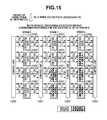
- FIG. 15 illustrates an exemplary configuration of a control unit and a processing unit of a conventional information processing apparatus.
- processing time taken in processing by an identification device in each stage (T) and a successful detection rate (p) have the following relationship.
- the identification devices 1061 and 1062 are idled for 50 and 75 cycles, respectively. More specifically, in executing processing whose successful detection rate is less than 1 (100%) in cascade processing, the operation rate of the processing in later stages of the pipeline may decrease, which may result in processing inefficiency.
- all the modules are provided to all of the identification devices 1060 through 1062 included in the processing unit 106 .
- control units 1050 through 1053 transmit the input data via the data lines and the valid lines for each pipeline.
- the control units 1050 through 1053 transmit the data “data_out0[0]” via the data line (“data_in0[1]”) and transmit the control signal valid_out0[0] via the valid line (“valid0[1]”) (i.e., data_out0[0] ⁇ data_in0′′[1], valid_out0[0] ⁇ valid_in0[1], data_out0[1] ⁇ “data_in0”[2], valid_out0[1] ⁇ valid_in0[2])).
- the processing inefficiency in which the operation rate in the later pipelines decreases, may very often occur.
- the conventional method has the defectives caused due to the above-described principle.
- FIG. 1 is a block diagram illustrating an exemplary configuration of an information processing apparatus according to the present exemplary embodiment.
- the information processing apparatus includes a CPU 100 , a ROM 101 , a DRAM controller 102 , a DRAM 103 , a control unit 105 , and a processing unit 106 .
- the ROM 101 includes a processing setting data storage unit 104 , a successful detection rate storage unit 107 , and a processing time storage unit 108 .
- the CPU 100 can function as a calculation unit 109 by executing a calculation program stored on the ROM 101 .
- the successful detection rate storage unit 107 stores a previously acquired successful detection rate (the probability of execution of the subsequent processing based on a result of arbitrary processing).
- the processing time storage unit 108 stores the processing time of each processing, which has been previously acquired.
- the calculation unit 109 calculates a module configuration for executing each processing based on the successful detection rate stored on the successful detection rate storage unit 107 and the processing time stored on the processing time storage unit 108 .
- the processing setting data storage unit 104 stores setting data of a characteristic amount and setting data of positional information about (the address of) image data.
- the CPU 100 acquires the setting data of a characteristic amount from the processing setting data storage unit 104 .
- the CPU 100 set the acquired setting data on an identification device (a processing execution unit) included in the processing unit 106 .
- the CPU 100 acquires setting data of positional information about (the address of) image data.
- the CPU 100 sets the acquired setting data on the control unit 105 .
- the CPU 100 After completing the setting of the control unit 105 and the processing unit 106 , the CPU 100 notifies the control unit 105 and the processing unit 106 that the processing has been started. Then, the control unit 105 accesses the DRAM controller 102 based on the image data positional information (the address) set thereon. Accordingly, the control unit 105 serially reads data of rectangular areas from the image data stored in the DRAM 103 . In addition, the control unit 105 transfers the read rectangular area image data to the processing unit 106 . After receiving the rectangular area image data from the control unit 105 , the processing unit 106 serially executes identification processing on the received rectangular area image data.
- the control unit 105 notifies the CPU 100 that identification target data is to be changed.
- the CPU 100 similarly to the operation described above, acquires setting data of a characteristic amount corresponding to new identification target data from the processing setting data storage unit 104 .
- the CPU 100 sets the acquired setting data on an identification device provided in the processing unit 106 .
- the CPU 100 acquires setting data of positional information of image data corresponding to the new identification target data from the processing setting data storage unit 104 .
- the CPU 100 sets the acquired setting data on the control unit 105 . In the above-described manner, the identification target data can be changed.
- the calculation unit 109 uses the successful detection rate storage unit 107 and the processing time storage unit 108 to calculate a module configuration.
- the CPU 100 executes data processing such as face detection processing based on the calculated module configuration.
- FIG. 2 illustrates an exemplary configuration of a control unit and a processing unit according to the present exemplary embodiment.
- Td[N] be the processing time of each identification device provided at a stage N.
- P[N] be the cumulative successful detection rate at the stage N.
- the calculation unit 109 uses the successful detection rate storage unit 107 and the processing time storage unit 108 to calculate a module configuration (an appropriate number of identification devices for each stage).
- an information processing unit includes at least one identification device for each stage.
- the calculation unit 109 can calculate the above-described expression (4) based on the cumulative successful detection rate and the processing time for each identification device respectively stored on the successful detection rate storage unit 107 and the processing time storage unit 108 .
- the control device 1050 transmits four pieces of rectangular image data to the stage 0 in order to execute spatially paralleled processing.
- the four pieces of rectangular image data includes data_in0, 1, 2, and 3.
- valid signals valid_in0, 1, 2, and 3 are transmitted in association with the data_in0, 1, 2, and 3.
- the control device 1050 is connected to each corresponding identification device.
- the identification device executes True/False identification processing.
- the identification device outputs a result of the identification processing as control signals valid_out0, 1, 2, and 3.
- the identification devices are connected as follows: data_out1[0] ⁇ data_in0[2] valid_out1[0] ⁇ valid_in0[2].
- the present exemplary embodiment executes identification processing in the above-described manner.
- FIGS. 4A through 4C illustrate an operation state of the identification device in the example 1 illustrated in FIG. 3 .
- the time is taken on a horizontal axis (extended rightwards in the drawing) and the number of spatially paralleled processing (the number of modules that operate in parallel to one another in a unitary time period) is taken on a vertical axis (extended downwards in the drawing).
- the number of modules is determined according to the ratio calculated by the calculation unit 109 (i.e., “4:2:1”) and the modules of the determined number are provided.
- the identification device 1061 executes the processing based on a result of the processing in time 1 .
- the processing time of the control devices 1050 through 1052 does not affect the difference between the total processing time lengths of the conventional method and the present exemplary embodiment. Accordingly, the description thereof is omitted.
- the four identification devices 1060 start the processing. After the time 1 has elapsed, the identification devices 1060 output a processing result. Because the successful detection rate of the identification device 1060 is 1 ⁇ 2, two of the four identification devices 1060 output a processing result “True” while the other two outputs “False”. Accordingly, in the module configuration illustrated in FIG. 4A , after the time 1 has elapsed, two of the four identification devices 1061 only start executing the processing.
- the number of identification devices in operation in this case is illustrated in FIG. 4B .
- time 2 two identification devices 1061 is in operation.
- two identification devices 1061 operate.
- one identification device 1062 operates.
- the number of the identification devices 1060 is always four. In other words, if the successful detection rate in the example 1 is always maintained (i.e., if the successful detection rate in the example 1 is always close to the set successful detection rate), then the number of identification devices is as illustrated in FIG. 4B . In other words, the maximum number of identification devices 1061 that simultaneously operate is two while the maximum number of identification devices 1062 that simultaneously operate is only one.
- the module configuration according to the present exemplary embodiment include a pipeline to which no identification device is provided as illustrated in FIG. 4C . Accordingly, the control device executes the processing by connecting to a predetermined later-stage identification device according to whether the data input at the previous stage is valid.
- the processing performance of the module configuration of the conventional method ( FIG. 15 ) and that according to the present exemplary embodiment ( FIG. 2 ) are similar. Accordingly, the present exemplary embodiment can implement the similar processing performance with a circuit configuration smaller than that of the conventional method.
- the present exemplary embodiment can implement a processing module configuration more appropriate than that of the conventional method.
- the successful detection rate may vary according to the validity of the input data, the number of the operating modules illustrated in FIGS. 4A and 4B does not always apply. However, in executing identification processing on all images, the set successful detection rate may be achieved on average. Accordingly, by using the module configuration calculated by the calculation unit 109 , it is not necessary in the present exemplary embodiment to provide a wasteful processing module with substantially the same processing time as that of the conventional method.
- FIGS. 5A and 5B illustrate an exemplary operation state of the identification device in the example 2 illustrated in FIG. 3 .
- the present exemplary embodiment determines the number of each of the identification devices 1060 through 1062 according to the result of the calculation by the calculation unit 109 .
- the processing performance of the module configuration of the conventional method ( FIG. 15 ) and that according to the present exemplary embodiment ( FIG. 2 ) are similar.
- the total processing time is limited to the processing time for processing the stage whose processing time is the longest. Accordingly, in dividing processing into a plurality of stages, it is useful to divide the processing into stages so that the processing time lengths of the stages are the same as one another.
- the processing time of each stage is determined by learning. Accordingly, the processing time lengths of the stages may not always be set to the same processing time length.
- the calculation unit 109 calculates the number of the identification devices (modules) to be provided to execute processing of the stages according to the length of the processing time. Accordingly, the present exemplary embodiment can increase the degree of evenness of the processing time lengths of the plurality of stages. In the examples 3 and 4 described below, the stages have different processing time lengths.
- FIG. 6 illustrates an operation status of the identification device in the module configuration of the conventional method in the example 3 illustrated in FIG. 3 .
- the present exemplary embodiment determines the number of each of the identification devices 1060 through 1062 according to the result of the calculation by the calculation unit 109 .
- the processing performance of the module configuration of the conventional method ( FIG. 15 ) and that according to the present exemplary embodiment are similar.
- FIG. 7 illustrates an operation status of the identification device in the module configuration of the conventional method in the example 4 illustrated in FIG. 3 .
- a value “3” is set as the value of the number of paralleled processing. Accordingly, three identification devices 1060 through 1062 each are provided.
- the stages have different processing time lengths.
- the present exemplary embodiment determines the number of each of the identification devices 1060 through 1062 according to the result of the calculation by the calculation unit 109 .
- the processing performance of the module configuration of the conventional method ( FIG. 15 ) and that according to the present exemplary embodiment are similar.
- the present exemplary embodiment provides the identification devices in the number that is determined according to the ratio of the numbers of the modules calculated by the calculation unit 109 . Accordingly, the present exemplary embodiment can improve the efficiency of operation of the identification devices.
- the ratio of the numbers of the modules may not have an integral value according to the number of modules that can be provided. Furthermore, even if the ratio of the numbers of the modules has an integral value, it may be impossible to provide the identification devices in the number equivalent to the calculated ratio due to the limitation on the total number of modules that can be provided. More specifically, if the total number of modules that can be provided is six in the above-described example 1, then the module configuration satisfying the ratio “4:2:1” cannot be implemented.
- the ratio of the number of the modules calculated by the calculation unit 109 does not have an integral value, or if the calculated total number of modules does not satisfy the ratio of the numbers of modules calculated by the calculation unit 109 , it is useful to determine the ratio of the numbers of modules by executing the following method.
- a plurality of alternative configurations exist as to what quantity of identification devices are to be assigned to which stage.
- the present exemplary embodiment extracts alternative configurations by which one or more identification devices are provided to all the stages from among all the alternative configurations. The condition for extracting the above-described alternative configuration is appropriate because if any stage is not provided with an identification device, the processing may not be completed.
- the present exemplary embodiment executes a second module quantity ratio determination method described below.
- the present exemplary embodiment calculates the processing time T [N] for processing one piece of input data (rectangular image data) at the stage N for all the stages by using the above-described expression (2).
- the present exemplary embodiment sets the maximum value of the calculated values of the processing time T[N] as a first processing time of the alternative configuration.
- the maximum processing time length of the processing time lengths of all the stages limits the total processing time length in executing pipeline processing, it is appropriate and useful to set the maximum value of the stage processing time length values (the first processing time) as the entire processing time length value.
- the present exemplary embodiment extracts an alternative whose first processing time value is smallest from among all the alternative configurations extracted by the first module quantity determination method. Furthermore, the present exemplary embodiment determines the alternative configuration extracted by the second module quantity determination method as the module configuration to be applied. More specifically, the present exemplary embodiment calculates sequences each including values of the expression “T[N] ⁇ P[N]/Num[N]”, which are arranged in descending order, for each alternative configuration. Furthermore, the present exemplary embodiment compares the values of the terms of each sequence starting from the first term. In addition, the present exemplary embodiment extracts a sequence having a value of a smallest term. However, if a plurality of alternative configurations have been extracted as a result of the above-described second module quantity determination method, the present exemplary embodiment further applies a third module quantity determination method described below.
- the present exemplary embodiment calculates the processing time T [N] for processing one piece of input data (rectangular image data) at the stage N for all the stages by using the above-described expression (2). Furthermore, the present exemplary embodiment sets a value second largest of the values calculated in the above-described manner as a value of a second processing time of the alternative configuration. In addition, the present exemplary embodiment extracts an alternative configuration whose second processing time value is smallest from among all the alternative configurations extracted in the second module quantity determination method. Moreover, the present exemplary embodiment determines the alternative configuration extracted by the third module quantity determination method as the module configuration to be applied.
- the present exemplary embodiment executes comparison similar to that described above by using a third largest value (third processing time), a fourth largest value (fourth processing time), and so on. In this case, the present exemplary embodiment completes the extraction when only one alternative configuration whose N-th processing time value is the smallest remains.
- the present exemplary embodiment arbitrarily select one alternative configuration from among the plurality of alternative configurations and determines the extracted alternative configuration as the module configuration to be applied. More specifically, if a plurality of sequences have been selected even after the comparison on the last terms thereof are completed, then the present exemplary embodiment determines the module configuration according to the number of modules corresponding to either one of the selected plurality of sequences.
- FIG. 8 illustrates an exemplary method in which the above-described method is applied in the example 1 illustrated in FIG. 3 .
- the present exemplary embodiment determines the module configuration in the following manner.
- the present exemplary embodiment extracts alternative configurations 1 through 10, by which at least one identification device is provided to all the stages.
- the present exemplary embodiment calculates the processing time T[N] for one piece of input data (rectangular image data) input at the stage N for all the stages by using the expression (2).
- the present exemplary embodiment sets the highest value of the values of the processing time T[N] as the first processing time of the alternative configuration. Furthermore, the present exemplary embodiment extracts an alternative configuration whose first processing time value is the smallest of all the alternative configurations extracted by the first module quantity determination method. In the example illustrated in FIG. 8 , only one alternative configuration has a stage processing time maximum value of 1 ⁇ 3, which is smaller than those of the other alternative configurations. Accordingly, the present exemplary embodiment determines the alternative configuration 2 as the module configuration to be applied.
- FIG. 9 illustrates an exemplary method in which the above-described method is applied in the example 3 illustrated in FIG. 3 .
- the present exemplary embodiment determines the module configuration in the following manner.
- the present exemplary embodiment extracts alternative configurations 1 through 10, by which at least one identification device is provided to all the stages.
- the present exemplary embodiment calculates the processing time T [N] for one piece of input data (rectangular image data) input at the stage N for all the stages by using the expression (2).
- the present exemplary embodiment sets the highest value of the values of the processing time T[N] as the first processing time of the alternative configuration.
- the present exemplary embodiment extracts an alternative configuration whose first processing time value is the smallest of all the alternative configurations extracted by the first module quantity determination method.
- the present exemplary embodiment cannot determine the module configuration at this timing. Accordingly, the present exemplary embodiment executes the third module quantity determination method. In the third module quantity determination method, the present exemplary embodiment compares second longest stage processing time lengths.
- the present exemplary embodiment determines the alternative configuration 5 as the module configuration to be applied. By executing the above-described module quantity determination method, the present exemplary embodiment can select an appropriate module configuration.
- FIG. 10A illustrates the module configuration determined according to the number of modules calculated by the calculation unit 109 under the conditions of the example 2.
- FIG. 10B illustrates the module configuration determined according to the number of modules calculated by the calculation unit 109 under the conditions of the example 3.
- the identification target (from the example 2 (a person's face) to the example 3 (a person)) can be changed by changing one of the identification device 1061 provided for the stage 1 ( FIG. 10A ) to the identification device 1062 provided for the stage 2 ( FIG. 10B ).
- FIG. 11A corresponds to the module configuration in the example 2 while the example illustrated in FIG. 11B corresponds to the module configuration in the example 3.
- identification devices 200 through 207 eight identification devices 200 through 207 are provided.
- four identification devices 1060 , three identification devices 1061 , and one identification device 1062 are provided for executing processing in each of the stages 0 through 2 in the example 2 according to the processing time and the successful detection rate set for each stage.
- the present exemplary embodiment changes the numbers of each of the identification devices 1060 through 1062 , which have been provided to execute the processing in each stage, to four, two, and two, respectively, as illustrated in FIG. 11B .
- the identification devices are connected to a network (Interconnect) 80 .
- each of the identification devices transmits status information indicating that the identification processing is currently executed to the network (Interconnect) 80 .
- the method for determining the destination (identification device) of transmission of a result of identification processing by a specific identification device can be implemented by using a communication path setting unit provided on the network (Interconnect) 80 .
- the present exemplary embodiment sets the setting so that the output from the identification devices 200 through 203 , each of which is provided to execute the processing at the stage 0 , is to be transmitted to the identification devices 204 through 206 , each of which executes the processing at the stage 1 .
- the present exemplary embodiment sets the setting so that the output from the identification devices 204 through 206 are transmitted to the identification device 207 , which executes the processing at the stage 2 .
- the present exemplary embodiment determines the content of the setting according to a result of the calculation (as to the module configuration) executed by the calculation unit 109 .
- the present exemplary embodiment can implement the module configuration illustrated in FIG. 11B (the example 3).
- the network (Interconnect) 80 executes control for selecting one identification device from among the identification devices that have not transmitted status information indicating that the identification processing is currently executed (i.e., the identification devices that have not asserted a “busy” signal) and for establishing a connection. However, if all the transmission destinations are currently executing identification processing, the network (Interconnect) 80 establishes a connection after extracting at least one identification device that is not currently executing identification processing.
- the identification device can include a processor.
- FIG. 12 illustrates an example of the identification device including a processor according to the present exemplary embodiment.
- the method for changing the identification target from the example 2 ( FIG. 11A ) to the example 3 ( FIG. 11B ) can be implemented only by changing the program that the processor executes. More specifically, the present exemplary embodiment can change the module configuration by changing the program that the processor 306 illustrated in FIG. 12 from the processing program for the stage 1 to the processing program for the stage 2 .
- identification processing In identification processing, generally, several tens of stages are set as the cascaded stages. Accordingly, it may be difficult to provide one or more identification devices to each stage due to the restriction of the circuit configuration size. In this case, it is useful to integrate a plurality of continuous stages and provide an identification device to the integrated stages to reduce the size of the circuit configuration.
- the present exemplary embodiment can provide a larger number of alternative configurations than the number of processors. Accordingly, the present exemplary embodiment can determine a highly appropriate module configuration.
- aspects of the present invention can also be realized by a computer of a system or apparatus (or devices such as a CPU or MPU) that reads out and executes a program recorded on a memory device to perform the functions of the above-described embodiments, and by a method, the steps of which are performed by a computer of a system or apparatus by, for example, reading out and executing a program recorded on a memory device to perform the functions of the above-described embodiments.
- the program is provided to the computer for example via a network or from a recording medium of various types serving as the memory device (e.g., computer-readable medium).
Landscapes
- Engineering & Computer Science (AREA)
- Software Systems (AREA)
- Physics & Mathematics (AREA)
- General Physics & Mathematics (AREA)
- Multimedia (AREA)
- Theoretical Computer Science (AREA)
- Image Processing (AREA)
Abstract
Description
(S×p[0]×p[1]× . . . ×p[N−2])×p[N−1].
| TABLE 1 | ||||
| Cumulative | ||||
| Processing | Successful | Successful | ||
| time | detection rate | | ||
| Stage |
| 0 | 1 | 1/2 | 1 | |
| |
1 | 1/2 | 1/2 | |
| |
1 | 1/2 | 1/4 | |
Tm[0]=Tm[1]=Tm[2]=1
p[0]=p[1]=p[2]=½.
Td[N]=Tm[N]×P[N] (1).
Because Td[N] denotes an average processing time taken by each identification device, if a plurality of identification devices (modules) capable of executing processing of the same stage, the processing at the stage can be sharedly executed by the plurality of identification devices.
T[N]=Td[N]/Num[N]=(Tm[N]×P[N])/Num[N] (2).
Substitution of the processing time Tm and the cumulative successful detection rate P for one identification device in the example 1 into the expression (3) leads to the following expression:
which then leads to the following expression (4):
Num[0]:Num[1]:Num[2]=4:2:1 (4).
data_out0[0]→data_in0[1]
valid_out0[0]→valid_in0[1]
data_out1[0]→data_in1[1]
valid_out1[0]→valid_in1[1].
data_out1[0]→data_in0[2]
valid_out1[0]→valid_in0[2].
The present exemplary embodiment executes identification processing in the above-described manner.
Tm[0]=Tm[1]=Tm[2]=1
p[0]=¾
p[1]=⅓
p[2]=¼.
Tm[0]=1, Tm[1]=2, Tm[2]=4,
p[0]=¼, p[1]=½, p[2]=¾.
In other words, in the example 3, the stages have different processing time lengths.
Tm[0]=1, Tm[1]=2, Tm[2]=4,
p[0]=⅙, p[1]=½, p[2]= 1/16.
In other words, in the example 4 also, the stages have different processing time lengths.
Claims (13)
Applications Claiming Priority (2)
| Application Number | Priority Date | Filing Date | Title |
|---|---|---|---|
| JP2008-258966 | 2008-10-03 | ||
| JP2008258966A JP5100596B2 (en) | 2008-10-03 | 2008-10-03 | Information processing apparatus and information processing method |
Publications (2)
| Publication Number | Publication Date |
|---|---|
| US20100122063A1 US20100122063A1 (en) | 2010-05-13 |
| US9213906B2 true US9213906B2 (en) | 2015-12-15 |
Family
ID=42166250
Family Applications (1)
| Application Number | Title | Priority Date | Filing Date |
|---|---|---|---|
| US12/572,090 Active 2032-06-27 US9213906B2 (en) | 2008-10-03 | 2009-10-01 | Information processing apparatus and method |
Country Status (2)
| Country | Link |
|---|---|
| US (1) | US9213906B2 (en) |
| JP (1) | JP5100596B2 (en) |
Families Citing this family (8)
| Publication number | Priority date | Publication date | Assignee | Title |
|---|---|---|---|---|
| JP5574816B2 (en) * | 2010-05-14 | 2014-08-20 | キヤノン株式会社 | Data processing apparatus and data processing method |
| JP5618670B2 (en) | 2010-07-21 | 2014-11-05 | キヤノン株式会社 | Data processing apparatus and control method thereof |
| JP5789128B2 (en) * | 2011-05-26 | 2015-10-07 | キヤノン株式会社 | Image processing apparatus, image data processing method and program |
| EP3072439B1 (en) * | 2013-10-28 | 2018-09-05 | Fujifilm Corporation | Image processing device and operation method therefor |
| JP6603477B2 (en) * | 2015-04-30 | 2019-11-06 | キヤノン株式会社 | Information processing apparatus and information processing method |
| JP5974148B2 (en) * | 2015-08-03 | 2016-08-23 | キヤノン株式会社 | Image processing apparatus, image data processing method and program |
| JP6815743B2 (en) | 2016-04-15 | 2021-01-20 | キヤノン株式会社 | Image processing equipment and its methods, programs |
| JP6644231B1 (en) * | 2019-04-26 | 2020-02-12 | Awl株式会社 | Image analysis device and image analysis system |
Citations (2)
| Publication number | Priority date | Publication date | Assignee | Title |
|---|---|---|---|---|
| US20030163512A1 (en) | 2002-02-28 | 2003-08-28 | Fujitsu Limited | Parallel-process execution method and multiprocessor-type computer |
| US20040032512A1 (en) * | 1997-05-15 | 2004-02-19 | Kia Silverbrook | Correction of distortions in digital images |
Family Cites Families (6)
| Publication number | Priority date | Publication date | Assignee | Title |
|---|---|---|---|---|
| JP2982038B2 (en) * | 1994-04-01 | 1999-11-22 | 東京エレクトロン株式会社 | Scheduling method and apparatus for processing of object to be processed |
| JP2001103304A (en) * | 1999-07-29 | 2001-04-13 | Fuji Photo Film Co Ltd | Specific subject extraction method and apparatus |
| JP4619927B2 (en) * | 2005-11-01 | 2011-01-26 | 富士フイルム株式会社 | Face detection method, apparatus and program |
| JP2008026974A (en) * | 2006-07-18 | 2008-02-07 | Mitsubishi Electric Corp | Person tracking device |
| JP2008077370A (en) * | 2006-09-21 | 2008-04-03 | Renesas Technology Corp | Production management system and production management method |
| JP2008102611A (en) * | 2006-10-17 | 2008-05-01 | Canon Inc | Image processing device |
-
2008
- 2008-10-03 JP JP2008258966A patent/JP5100596B2/en not_active Expired - Fee Related
-
2009
- 2009-10-01 US US12/572,090 patent/US9213906B2/en active Active
Patent Citations (3)
| Publication number | Priority date | Publication date | Assignee | Title |
|---|---|---|---|---|
| US20040032512A1 (en) * | 1997-05-15 | 2004-02-19 | Kia Silverbrook | Correction of distortions in digital images |
| US20030163512A1 (en) | 2002-02-28 | 2003-08-28 | Fujitsu Limited | Parallel-process execution method and multiprocessor-type computer |
| JP2003256221A (en) | 2002-02-28 | 2003-09-10 | Fujitsu Ltd | Parallel process execution method and multiprocessor computer |
Non-Patent Citations (3)
| Title |
|---|
| Albonesi et al., "Dynamically Tuning Processor Resources with Adaptive Processing", Dec. 2003, IEEE. * |
| Bannister et al., "Task Allocation in Fault-Tolerant Distributed Systems", 1983, Acta Informatica 20, pp. 261-281. * |
| Paul Viola et al., Robust Real-time Object Detection, Proceedings of IEEE workshop on Statistical and Computational Theories of Vision, Vancouver, CA, Jul. 13, 2001, pp. 1-25. |
Also Published As
| Publication number | Publication date |
|---|---|
| JP2010092123A (en) | 2010-04-22 |
| JP5100596B2 (en) | 2012-12-19 |
| US20100122063A1 (en) | 2010-05-13 |
Similar Documents
| Publication | Publication Date | Title |
|---|---|---|
| US9213906B2 (en) | Information processing apparatus and method | |
| US20230030267A1 (en) | Method and apparatus for selecting face image, device, and storage medium | |
| US8891877B2 (en) | Data processing apparatus and control method thereof | |
| US10380414B2 (en) | Method and system of facial expression recognition using linear relationships within landmark subsets | |
| US8213690B2 (en) | Image processing apparatus including similarity calculating unit, image pickup apparatus, and processing method for the apparatuses | |
| US8861784B2 (en) | Object recognition apparatus and object recognition method | |
| US20200342258A1 (en) | Image analysis device and image analysis system | |
| CN105139040A (en) | A method and system for detecting queuing status information | |
| CN109740589B (en) | Asynchronous object ROI detection method and system in video mode | |
| US12236580B2 (en) | Detection method, electronic device and non-transitory computer-readable storage medium | |
| CN104781828B (en) | Accelerated object detection filter using video motion estimation module | |
| CN108701355B (en) | GPU optimization and online single Gaussian based skin likelihood estimation | |
| CN110784644B (en) | Image processing method and device | |
| CN118138801B (en) | Video data processing method and device, electronic equipment and storage medium | |
| WO2020119411A1 (en) | Method for transmitting image, terminal and storage medium | |
| JP4021873B2 (en) | Face image monitoring system | |
| CN114514552A (en) | Electronic device and image processing method of electronic device | |
| KR102557572B1 (en) | Artificial neural network device and operating method for the same | |
| JP5686548B2 (en) | Information processing apparatus, information processing method, and program | |
| US9003167B2 (en) | Data processing apparatus and data processing method | |
| WO2009130899A1 (en) | Image processing device, image processing method, and integrated circuit for processing images | |
| JP2019207639A (en) | Information processing device, imaging apparatus, information processing method, and, program | |
| US8792731B2 (en) | Image processing apparatus, image data processing method, and storage medium | |
| EP2777014B1 (en) | Method and apparatus for tightly coupled, low power image processing | |
| JP6658402B2 (en) | Frame rate determination device, frame rate determination method, and computer program for frame rate determination |
Legal Events
| Date | Code | Title | Description |
|---|---|---|---|
| AS | Assignment |
Owner name: CANON KABUSHIKI KAISHA,JAPAN Free format text: ASSIGNMENT OF ASSIGNORS INTEREST;ASSIGNORS:MISE, RYOKO;SHIRAGA, SHINJI;REEL/FRAME:023803/0971 Effective date: 20091217 Owner name: CANON KABUSHIKI KAISHA, JAPAN Free format text: ASSIGNMENT OF ASSIGNORS INTEREST;ASSIGNORS:MISE, RYOKO;SHIRAGA, SHINJI;REEL/FRAME:023803/0971 Effective date: 20091217 |
|
| STCF | Information on status: patent grant |
Free format text: PATENTED CASE |
|
| MAFP | Maintenance fee payment |
Free format text: PAYMENT OF MAINTENANCE FEE, 4TH YEAR, LARGE ENTITY (ORIGINAL EVENT CODE: M1551); ENTITY STATUS OF PATENT OWNER: LARGE ENTITY Year of fee payment: 4 |
|
| MAFP | Maintenance fee payment |
Free format text: PAYMENT OF MAINTENANCE FEE, 8TH YEAR, LARGE ENTITY (ORIGINAL EVENT CODE: M1552); ENTITY STATUS OF PATENT OWNER: LARGE ENTITY Year of fee payment: 8 |