US9207139B2 - Mass flow control monitoring - Google Patents
Mass flow control monitoring Download PDFInfo
- Publication number
- US9207139B2 US9207139B2 US13/479,965 US201213479965A US9207139B2 US 9207139 B2 US9207139 B2 US 9207139B2 US 201213479965 A US201213479965 A US 201213479965A US 9207139 B2 US9207139 B2 US 9207139B2
- Authority
- US
- United States
- Prior art keywords
- mfc
- chamber
- period
- fill
- signals
- Prior art date
- Legal status (The legal status is an assumption and is not a legal conclusion. Google has not performed a legal analysis and makes no representation as to the accuracy of the status listed.)
- Active, expires
Links
Images


Classifications
-
- G—PHYSICS
- G01—MEASURING; TESTING
- G01F—MEASURING VOLUME, VOLUME FLOW, MASS FLOW OR LIQUID LEVEL; METERING BY VOLUME
- G01F25/00—Testing or calibration of apparatus for measuring volume, volume flow or liquid level or for metering by volume
-
- G—PHYSICS
- G01—MEASURING; TESTING
- G01F—MEASURING VOLUME, VOLUME FLOW, MASS FLOW OR LIQUID LEVEL; METERING BY VOLUME
- G01F25/00—Testing or calibration of apparatus for measuring volume, volume flow or liquid level or for metering by volume
- G01F25/10—Testing or calibration of apparatus for measuring volume, volume flow or liquid level or for metering by volume of flowmeters
- G01F25/17—Testing or calibration of apparatus for measuring volume, volume flow or liquid level or for metering by volume of flowmeters using calibrated reservoirs
-
- G—PHYSICS
- G01—MEASURING; TESTING
- G01L—MEASURING FORCE, STRESS, TORQUE, WORK, MECHANICAL POWER, MECHANICAL EFFICIENCY, OR FLUID PRESSURE
- G01L13/00—Devices or apparatus for measuring differences of two or more fluid pressure values
-
- G—PHYSICS
- G01—MEASURING; TESTING
- G01D—MEASURING NOT SPECIALLY ADAPTED FOR A SPECIFIC VARIABLE; ARRANGEMENTS FOR MEASURING TWO OR MORE VARIABLES NOT COVERED IN A SINGLE OTHER SUBCLASS; TARIFF METERING APPARATUS; MEASURING OR TESTING NOT OTHERWISE PROVIDED FOR
- G01D21/00—Measuring or testing not otherwise provided for
- G01D21/02—Measuring two or more variables by means not covered by a single other subclass
-
- G—PHYSICS
- G01—MEASURING; TESTING
- G01F—MEASURING VOLUME, VOLUME FLOW, MASS FLOW OR LIQUID LEVEL; METERING BY VOLUME
- G01F1/00—Measuring the volume flow or mass flow of fluid or fluent solid material wherein the fluid passes through a meter in a continuous flow
- G01F1/76—Devices for measuring mass flow of a fluid or a fluent solid material
-
- G01F25/0038—
-
- G01F25/0053—
-
- G—PHYSICS
- G01—MEASURING; TESTING
- G01F—MEASURING VOLUME, VOLUME FLOW, MASS FLOW OR LIQUID LEVEL; METERING BY VOLUME
- G01F25/00—Testing or calibration of apparatus for measuring volume, volume flow or liquid level or for metering by volume
- G01F25/10—Testing or calibration of apparatus for measuring volume, volume flow or liquid level or for metering by volume of flowmeters
- G01F25/15—Testing or calibration of apparatus for measuring volume, volume flow or liquid level or for metering by volume of flowmeters specially adapted for gas meters
-
- G—PHYSICS
- G05—CONTROLLING; REGULATING
- G05D—SYSTEMS FOR CONTROLLING OR REGULATING NON-ELECTRIC VARIABLES
- G05D7/00—Control of flow
-
- G—PHYSICS
- G06—COMPUTING OR CALCULATING; COUNTING
- G06F—ELECTRIC DIGITAL DATA PROCESSING
- G06F17/00—Digital computing or data processing equipment or methods, specially adapted for specific functions
Definitions
- This invention relates to a method for monitoring a Mass Flow Controller (MFC) connected to a pressure chamber for supplying gas to the chamber.
- MFC Mass Flow Controller
- Mass Flow Controllers are used to supply measured flows of gas to pressure chambers for a range of processes including etching semi-conductor substrates and depositing films thereon. Accurate flow rates can be extremely significant in the reproducibility of the process and also inaccuracies of the flow rate could result in a different process being performed due to the change in proportion of chemicals within the chamber.
- Mass Flow Controllers systems have therefore been developed already for monitoring Mass Flow Controllers to identify problems in their operation.
- these comprise arranging the desired flow rate at the MFC, allowing stabilising gas flow, allowing the fixed volume chamber to fill with gas for a fixed time or until a set pressure is achieved and determining the rate of fill of the gas into the chamber. During this test the chamber is not pumped. This rate value can be compared with a known good value to verify whether the MFC is operating correctly.
- the Applicant has developed methods which can mitigate against this problem.
- the invention consists in a method of monitoring a Mass Flow Controller (MFC) connected to a pressure chamber for supplying a gas to the chamber, which is in an unpumped condition, including cyclically switching the MFC to create successive fill cycles for a test period; and measuring the chamber pressure at intervals during the test period; characterised in that the total switch times of the MFC is at least 10 per cent of the fill cycle and in that the method includes obtaining the average of the pressure measurements and comparing them with historical data to determine whether or not the MFC is functioning properly.
- MFC Mass Flow Controller
- test period may be terminated when the chamber reaches a predetermined pressure or when a predetermined number of cycles have taken place.
- Each cycle may include a fill step and a delay (no fill) step.
- the length of the fill and or delay steps may be varied during the test cycle. It is to be understood that, as would be typical in the switched Bosch process, the MFC is not necessarily fully closed and or fully opened during the cycle. The test will work if the MFC is substantially closed and substantially opened.
- the cycle time may vary from about 0.1 seconds to about 60 seconds. In advanced switched Bosch processes times of ⁇ 1 s are highly desirable. Depending on the relative length of the switch time and the intended process time, the number of cycles appropriate can be selected. There must be at least two.
- the switch time for the MFC may be from about 10 milliseconds to about 200 milliseconds.
- the ratio of MFC switch time to cycle time may be between about 0.00017 and about 2.
- the method may include obtaining the gradient of pressure measurements and comparing the gradient with historical data to determine whether or not the MFC is functioning properly.
- the invention consists in a method of monitoring the operation of a Mass Flow Controller (MFC) connected to a chamber of supplying gas thereto including initiating a test phase where the MFC cyclically opened and closed for a period; measuring the chamber pressure at intervals; determining the gradient of the pressure increase; and determining the historical trend of measured gradients over time to indicate progressive variation in the performance of the MFC.
- MFC Mass Flow Controller
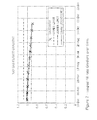
- FIG. 1 illustrates a rise in chamber pressure against a looping or cyclic fill rate
- FIG. 2 shows variations in the fill rate gradient over time
- FIG. 3 shows an example of a system to which the methods of the invention may be applied.
- the invention introduces the concept of a “short step/multi cycle” fill rate check, which can be used to identify MFCs that are slow to open or close.
- a test chamber fill rate is made up of a large number of short process steps whereby the MFC is turned on or off (or to a very low flow) for each successive step. This means the time taken for the MFC to turn the on/off makes up a significant portion of the total MFC ‘on’ time. Consequently any delays or variations in the on/off time should show up as a low/high fill rate reading thereby alerting the user to a problem.
- the test is particularly designed to pick up drift in MFC performance over a long period of the operation of the machine including the process chamber.
- slow to open responses of an MFC are plotted.
- Each cycle of the fill rate contains a “fill” and a “measure” step, which can each be a variable length.
- the number of cycles can be varied, in part as a reflection of the length of period of the process which is to be performed in the chamber.
- the end of the fill rate test period can be triggered either by the pressure achieved or a fixed number of cycles.
- the data from each loop or cycle in the fill rate can then be recorded by data logger. This data is used to plot the pressure/time graphs shown in FIG. 1 . These can be used to calculate the gradient of the test line and this information is stored.
- test data over a period of time can be plotted on a graph of a gradient against elapsed time. If the MFC is performing consistently the line plotted would be a straight line. However, if it becomes slow to open this will produce a plot having a negative gradient, whereas if it is fast to open the plot will have a positive gradient. Limits can be set to alert machine operators that the fill rate is outside normal bounds.
- This variation can be identified by stepping the MFC flow without setting the demand to 0 during each step so the value is dependant on the opening action of the MFC only.
- the MFC is ramped in equal steps until an ultimate chamber pressure is reached. This value is recorded in a data logger and a test is run a number of times to find the average value. The average value was then recorded and judged against upper and lower bounds. If the final pressure is decreased from the previous test the MFC can be said to be opening slowly. If the final pressure is increased from the previous test the MFC can be said to be opening quickly.
- the opening time for an MFC is typically ⁇ 100 msec but may lie in the range 50 to 400 msec. Closing times are in the range of 30 to 600 msec depending on the MFC and a common model has a closing time of 50 msec.
- the MFC opening and closing time may be in the region of 1 second, whilst the total fill cycle may be in the order of 60 seconds.
- the fill time can be hugely shortened so that the MFC time of 1 second contrasts with a total fill cycle of 500 msec.
- the MFC open and close times are a much greater proportion of the whole. It is thought that for effective testing it may be desirable to have the total MFC open and close times greater than 10% of the fill step (i.e. fill time plus MFC time).
- FIG. 3 shows an example of a system to which the afore-described methods of the invention may be applied.
- the system 300 of this example includes a pressure chamber 301 , a pressure gauge 302 , a mass flow controller (MFC) 303 , a control circuit 304 , a switch control circuit 305 , and a comparator circuit 306 .
- MFC mass flow controller
- the MFC 303 is connected to a pressure chamber 301 for supplying gas to the chamber 301 which is an unpumped condition.
- the switch control circuit 305 in communication with the control circuit 304 , cyclically switches the MFC 303 to create successive fill cycles for a test period; and the pressure gauge 302 is used to measure the chamber 301 pressure at intervals during the test period.
- the control circuit 304 obtains the average of the pressure measurements, and the comparator 306 compares them with historical data to generate a test output indicative of whether or not the MFC 303 is functioning properly.
- the MFC 303 again is connected to a pressure chamber 301 for supplying gas to the chamber 301 .
- a test phase is initiated where the MFC 303 is cyclically opened and closed by the switch control 305 for a period; and the chamber 301 pressure is measured at intervals using the pressure gauge 302 .
- the control circuit 304 determines the gradient of the pressure increase, and further determines the historical trend of measured gradients over time to generate a test output indicative of progressive variation in the performance of the MFC 303 .
- the comparator 306 of FIG. 3 may be omitted in this operational example.
- circuits 304 ⁇ 306 may be implemented by electronic hardware, processor driven software, and/or a combination thereof, and that any two or more of these circuits 304 ⁇ 306 may be combined.
Landscapes
- Physics & Mathematics (AREA)
- General Physics & Mathematics (AREA)
- Engineering & Computer Science (AREA)
- Fluid Mechanics (AREA)
- Theoretical Computer Science (AREA)
- Databases & Information Systems (AREA)
- General Engineering & Computer Science (AREA)
- Software Systems (AREA)
- Mathematical Physics (AREA)
- Data Mining & Analysis (AREA)
- Automation & Control Theory (AREA)
- Measuring Volume Flow (AREA)
- Flow Control (AREA)
- Testing Of Devices, Machine Parts, Or Other Structures Thereof (AREA)
- Fuel Cell (AREA)
Abstract
Description
Claims (15)
Priority Applications (1)
| Application Number | Priority Date | Filing Date | Title |
|---|---|---|---|
| US13/479,965 US9207139B2 (en) | 2011-05-26 | 2012-05-24 | Mass flow control monitoring |
Applications Claiming Priority (4)
| Application Number | Priority Date | Filing Date | Title |
|---|---|---|---|
| US201161490092P | 2011-05-26 | 2011-05-26 | |
| GB1108854.9 | 2011-05-26 | ||
| GBGB1108854.9A GB201108854D0 (en) | 2011-05-26 | 2011-05-26 | Mass flow controller monitoring |
| US13/479,965 US9207139B2 (en) | 2011-05-26 | 2012-05-24 | Mass flow control monitoring |
Publications (2)
| Publication Number | Publication Date |
|---|---|
| US20130138385A1 US20130138385A1 (en) | 2013-05-30 |
| US9207139B2 true US9207139B2 (en) | 2015-12-08 |
Family
ID=44279650
Family Applications (1)
| Application Number | Title | Priority Date | Filing Date |
|---|---|---|---|
| US13/479,965 Active 2034-01-22 US9207139B2 (en) | 2011-05-26 | 2012-05-24 | Mass flow control monitoring |
Country Status (7)
| Country | Link |
|---|---|
| US (1) | US9207139B2 (en) |
| EP (1) | EP2574884B1 (en) |
| JP (2) | JP6671090B2 (en) |
| KR (1) | KR101976845B1 (en) |
| CN (1) | CN102798441B (en) |
| GB (1) | GB201108854D0 (en) |
| TW (1) | TWI591465B (en) |
Cited By (8)
| Publication number | Priority date | Publication date | Assignee | Title |
|---|---|---|---|---|
| US9958302B2 (en) | 2011-08-20 | 2018-05-01 | Reno Technologies, Inc. | Flow control system, method, and apparatus |
| US10303189B2 (en) | 2016-06-30 | 2019-05-28 | Reno Technologies, Inc. | Flow control system, method, and apparatus |
| US10663337B2 (en) | 2016-12-30 | 2020-05-26 | Ichor Systems, Inc. | Apparatus for controlling flow and method of calibrating same |
| US10679880B2 (en) | 2016-09-27 | 2020-06-09 | Ichor Systems, Inc. | Method of achieving improved transient response in apparatus for controlling flow and system for accomplishing same |
| US10838437B2 (en) | 2018-02-22 | 2020-11-17 | Ichor Systems, Inc. | Apparatus for splitting flow of process gas and method of operating same |
| US11003198B2 (en) | 2011-08-20 | 2021-05-11 | Ichor Systems, Inc. | Controlled delivery of process gas using a remote pressure measurement device |
| US11144075B2 (en) | 2016-06-30 | 2021-10-12 | Ichor Systems, Inc. | Flow control system, method, and apparatus |
| US11899477B2 (en) | 2021-03-03 | 2024-02-13 | Ichor Systems, Inc. | Fluid flow control system comprising a manifold assembly |
Citations (3)
| Publication number | Priority date | Publication date | Assignee | Title |
|---|---|---|---|---|
| US5684245A (en) | 1995-11-17 | 1997-11-04 | Mks Instruments, Inc. | Apparatus for mass flow measurement of a gas |
| US20040261492A1 (en) * | 2003-06-25 | 2004-12-30 | Kaveh Zarkar | System and method for in-situ flow verification and calibration |
| US20080115560A1 (en) * | 2006-11-17 | 2008-05-22 | Shareef Iqbal A | Methods for performing actual flow verification |
Family Cites Families (11)
| Publication number | Priority date | Publication date | Assignee | Title |
|---|---|---|---|---|
| JPH0736547A (en) * | 1993-07-16 | 1995-02-07 | Yokogawa Electric Corp | Mass flow controller |
| JP3367811B2 (en) * | 1996-01-05 | 2003-01-20 | シーケーディ株式会社 | Gas piping system certification system |
| EP1484585B1 (en) | 1997-11-26 | 2010-09-15 | Invensys Systems, Inc. | Coriolis flowmeter with digital control system |
| US6311136B1 (en) | 1997-11-26 | 2001-10-30 | Invensys Systems, Inc. | Digital flowmeter |
| DE60207609T2 (en) * | 2001-04-24 | 2006-08-03 | Celerity Group, Inc., Santa Clara | Method for determining a valve opening for a mass flow controller |
| JP2008506116A (en) * | 2004-07-09 | 2008-02-28 | セレリティ・インコーポレイテッド | Method and system for flow measurement and mass flow regulator validation |
| US7474968B2 (en) * | 2005-03-25 | 2009-01-06 | Mks Instruments, Inc. | Critical flow based mass flow verifier |
| US20070224708A1 (en) * | 2006-03-21 | 2007-09-27 | Sowmya Krishnan | Mass pulse sensor and process-gas system and method |
| JP5058358B2 (en) * | 2010-09-30 | 2012-10-24 | 株式会社堀場エステック | Diagnostic mechanism |
| JP4874419B1 (en) * | 2010-12-03 | 2012-02-15 | 株式会社アドバンテスト | Switch device and test device |
| WO2012100181A1 (en) * | 2011-01-20 | 2012-07-26 | Hitachi Metals, Ltd. | Mass flow controller with onboard diagnostics, prognostics, and data logging |
-
2011
- 2011-05-26 GB GBGB1108854.9A patent/GB201108854D0/en not_active Ceased
-
2012
- 2012-04-26 EP EP12165776.1A patent/EP2574884B1/en active Active
- 2012-05-07 TW TW101116181A patent/TWI591465B/en active
- 2012-05-18 KR KR1020120053141A patent/KR101976845B1/en active Active
- 2012-05-24 CN CN201210163894.7A patent/CN102798441B/en active Active
- 2012-05-24 US US13/479,965 patent/US9207139B2/en active Active
- 2012-05-25 JP JP2012119596A patent/JP6671090B2/en active Active
-
2018
- 2018-04-12 JP JP2018077100A patent/JP2018152089A/en active Pending
Patent Citations (5)
| Publication number | Priority date | Publication date | Assignee | Title |
|---|---|---|---|---|
| US5684245A (en) | 1995-11-17 | 1997-11-04 | Mks Instruments, Inc. | Apparatus for mass flow measurement of a gas |
| US20040261492A1 (en) * | 2003-06-25 | 2004-12-30 | Kaveh Zarkar | System and method for in-situ flow verification and calibration |
| US6955072B2 (en) | 2003-06-25 | 2005-10-18 | Mks Instruments, Inc. | System and method for in-situ flow verification and calibration |
| US20080115560A1 (en) * | 2006-11-17 | 2008-05-22 | Shareef Iqbal A | Methods for performing actual flow verification |
| US7822570B2 (en) | 2006-11-17 | 2010-10-26 | Lam Research Corporation | Methods for performing actual flow verification |
Non-Patent Citations (1)
| Title |
|---|
| "PC2000 Process Tool User Interface and Control Software". |
Cited By (14)
| Publication number | Priority date | Publication date | Assignee | Title |
|---|---|---|---|---|
| US9958302B2 (en) | 2011-08-20 | 2018-05-01 | Reno Technologies, Inc. | Flow control system, method, and apparatus |
| US12228435B2 (en) | 2011-08-20 | 2025-02-18 | Ichor Systems, Inc. | Flow control system, method, and apparatus |
| US10782165B2 (en) | 2011-08-20 | 2020-09-22 | Ichor Systems, Inc. | Flow control system, method, and apparatus |
| US11003198B2 (en) | 2011-08-20 | 2021-05-11 | Ichor Systems, Inc. | Controlled delivery of process gas using a remote pressure measurement device |
| US10303189B2 (en) | 2016-06-30 | 2019-05-28 | Reno Technologies, Inc. | Flow control system, method, and apparatus |
| US12411502B2 (en) | 2016-06-30 | 2025-09-09 | Ichor Systems, Inc. | Flow control system, method, and apparatus |
| US10782710B2 (en) | 2016-06-30 | 2020-09-22 | Ichor Systems, Inc. | Flow control system, method, and apparatus |
| US11815920B2 (en) | 2016-06-30 | 2023-11-14 | Ichor Systems, Inc. | Flow control system, method, and apparatus |
| US11144075B2 (en) | 2016-06-30 | 2021-10-12 | Ichor Systems, Inc. | Flow control system, method, and apparatus |
| US11424148B2 (en) | 2016-09-27 | 2022-08-23 | Ichor Systems, Inc. | Method of achieving improved transient response in apparatus for controlling flow and system for accomplishing same |
| US10679880B2 (en) | 2016-09-27 | 2020-06-09 | Ichor Systems, Inc. | Method of achieving improved transient response in apparatus for controlling flow and system for accomplishing same |
| US10663337B2 (en) | 2016-12-30 | 2020-05-26 | Ichor Systems, Inc. | Apparatus for controlling flow and method of calibrating same |
| US10838437B2 (en) | 2018-02-22 | 2020-11-17 | Ichor Systems, Inc. | Apparatus for splitting flow of process gas and method of operating same |
| US11899477B2 (en) | 2021-03-03 | 2024-02-13 | Ichor Systems, Inc. | Fluid flow control system comprising a manifold assembly |
Also Published As
| Publication number | Publication date |
|---|---|
| US20130138385A1 (en) | 2013-05-30 |
| EP2574884B1 (en) | 2019-01-16 |
| TW201300981A (en) | 2013-01-01 |
| EP2574884A2 (en) | 2013-04-03 |
| CN102798441A (en) | 2012-11-28 |
| CN102798441B (en) | 2017-09-15 |
| JP2012248193A (en) | 2012-12-13 |
| JP6671090B2 (en) | 2020-03-25 |
| KR101976845B1 (en) | 2019-05-09 |
| KR20120132358A (en) | 2012-12-05 |
| JP2018152089A (en) | 2018-09-27 |
| EP2574884A3 (en) | 2014-05-28 |
| GB201108854D0 (en) | 2011-07-06 |
| TWI591465B (en) | 2017-07-11 |
Similar Documents
| Publication | Publication Date | Title |
|---|---|---|
| US9207139B2 (en) | Mass flow control monitoring | |
| JP5873681B2 (en) | Flow control device, diagnostic device used for flow control device, and diagnostic program | |
| US8321060B2 (en) | Method and system of on-tool and on-site MFC optimization providing consistent response | |
| US20150331430A1 (en) | Inspection method of flow sensor, inspection system and program recording medium with program for inspection system recorded thereon | |
| CN109538460B (en) | Fault diagnosis method and device for plunger pump | |
| KR102250969B1 (en) | Fluid control system and flow measurement method | |
| CN109237102A (en) | Fluid control device, control system, control method and program storage medium | |
| CN106253883A (en) | Device and method for measuring jitter built in chip | |
| KR20210114889A (en) | Flow rate diagnosis apparatus, flow rate diagnosis method, and storage medium storing thereon program for flow rate diagnosis apparatus | |
| US20100217562A1 (en) | Operating parameter control of an apparatus for processing data | |
| KR20160142362A (en) | Method and apparatus for monitoring the temperature of the coil wire of a solenoid valve | |
| US10031007B2 (en) | Method of calculating output flow rate of flow rate controller | |
| TW202520019A (en) | Method and apparatus for controlled splitting of fluid flows | |
| US8040995B2 (en) | Jitter detection circuit and jitter detection method | |
| US10248137B2 (en) | Method for controlling flow rate of fluid, mass flow rate control device for executing method, and mass flow rate control system utilizing mass flow rate control device | |
| US20060150019A1 (en) | Semiconductor device, test apparatus and measurement method therefor | |
| CN103511090B (en) | Control method and control system that a kind of fuel sprays | |
| KR20200105416A (en) | Flow rate calculation system, flow rate calculation system program, flow rate calculation method, and flow rate calculation device | |
| US12196597B2 (en) | Method for operating a flowmeter and flowmeter | |
| KR102785726B1 (en) | Multi-chamber variable rate system for gas flow verification | |
| JP2000227350A (en) | Judging device | |
| JP2023167672A (en) | Fluid control device, zero point adjustment method, and zero point adjustment program | |
| KR20210076500A (en) | Method for calculating opening time of an injector and control apparatus for fuel injection of an injector | |
| JP7751492B2 (en) | Servo valve evaluation system and servo valve evaluation method | |
| KR100811666B1 (en) | Tester |
Legal Events
| Date | Code | Title | Description |
|---|---|---|---|
| AS | Assignment |
Owner name: SPTS TECHNOLOGIES LIMITED, UNITED KINGDOM Free format text: ASSIGNMENT OF ASSIGNORS INTEREST;ASSIGNORS:JONES, SIMON;SONG, YIPING;SIGNING DATES FROM 20120521 TO 20120529;REEL/FRAME:028339/0845 |
|
| AS | Assignment |
Owner name: JPMORGAN CHASE BANK, N.A., AS ADMINISTRATIVE AGENT, ILLINOIS Free format text: SECURITY INTEREST;ASSIGNOR:SPTS TECHNOLOGIES LIMITED;REEL/FRAME:035364/0295 Effective date: 20150401 Owner name: JPMORGAN CHASE BANK, N.A., AS ADMINISTRATIVE AGENT Free format text: SECURITY INTEREST;ASSIGNOR:SPTS TECHNOLOGIES LIMITED;REEL/FRAME:035364/0295 Effective date: 20150401 |
|
| STCF | Information on status: patent grant |
Free format text: PATENTED CASE |
|
| AS | Assignment |
Owner name: SPTS TECHNOLOGIES LIMITED, UNITED KINGDOM Free format text: RELEASE BY SECURED PARTY;ASSIGNOR:JPMORGAN CHASE BANK, N.A.;REEL/FRAME:039257/0026 Effective date: 20160623 |
|
| MAFP | Maintenance fee payment |
Free format text: PAYMENT OF MAINTENANCE FEE, 4TH YEAR, LARGE ENTITY (ORIGINAL EVENT CODE: M1551); ENTITY STATUS OF PATENT OWNER: LARGE ENTITY Year of fee payment: 4 |
|
| MAFP | Maintenance fee payment |
Free format text: PAYMENT OF MAINTENANCE FEE, 8TH YEAR, LARGE ENTITY (ORIGINAL EVENT CODE: M1552); ENTITY STATUS OF PATENT OWNER: LARGE ENTITY Year of fee payment: 8 |