US9205543B1 - Driving head-changeable tool - Google Patents

Driving head-changeable tool Download PDF

Info

Publication number
US9205543B1
US9205543B1 US14/316,793 US201414316793A US9205543B1 US 9205543 B1 US9205543 B1 US 9205543B1 US 201414316793 A US201414316793 A US 201414316793A US 9205543 B1 US9205543 B1 US 9205543B1
Authority
US
United States
Prior art keywords
driving head
abutting
distance
central axis
peripheral edge
Prior art date
Legal status (The legal status is an assumption and is not a legal conclusion. Google has not performed a legal analysis and makes no representation as to the accuracy of the status listed.)
Active, expires
Application number
US14/316,793
Other versions
US20150375377A1 (en
Inventor
Hui-Chien CHEN
Chia-Yi Chen
Current Assignee (The listed assignees may be inaccurate. Google has not performed a legal analysis and makes no representation or warranty as to the accuracy of the list.)
YUAN LI HSING IND CO Ltd
Original Assignee
YUAN LI HSING IND CO Ltd
Priority date (The priority date is an assumption and is not a legal conclusion. Google has not performed a legal analysis and makes no representation as to the accuracy of the date listed.)
Filing date
Publication date
Application filed by YUAN LI HSING IND CO Ltd filed Critical YUAN LI HSING IND CO Ltd
Priority to US14/316,793 priority Critical patent/US9205543B1/en
Assigned to YUAN LI HSING INDUSTRIAL CO., LTD. reassignment YUAN LI HSING INDUSTRIAL CO., LTD. ASSIGNMENT OF ASSIGNORS INTEREST (SEE DOCUMENT FOR DETAILS). Assignors: CHEN, CHIA-YI, CHEN, HUI-CHIEN
Application granted granted Critical
Publication of US9205543B1 publication Critical patent/US9205543B1/en
Publication of US20150375377A1 publication Critical patent/US20150375377A1/en
Active legal-status Critical Current
Adjusted expiration legal-status Critical

Links

Images

Classifications

    • BPERFORMING OPERATIONS; TRANSPORTING
    • B25HAND TOOLS; PORTABLE POWER-DRIVEN TOOLS; MANIPULATORS
    • B25BTOOLS OR BENCH DEVICES NOT OTHERWISE PROVIDED FOR, FOR FASTENING, CONNECTING, DISENGAGING, OR HOLDING
    • B25B23/00Details of, or accessories for, spanners, wrenches, screwdrivers
    • B25B23/0007Connections or joints between tool parts
    • B25B23/0035Connection means between socket or screwdriver bit and tool
    • BPERFORMING OPERATIONS; TRANSPORTING
    • B25HAND TOOLS; PORTABLE POWER-DRIVEN TOOLS; MANIPULATORS
    • B25BTOOLS OR BENCH DEVICES NOT OTHERWISE PROVIDED FOR, FOR FASTENING, CONNECTING, DISENGAGING, OR HOLDING
    • B25B13/00Spanners; Wrenches
    • B25B13/02Spanners; Wrenches with rigid jaws
    • B25B13/06Spanners; Wrenches with rigid jaws of socket type
    • BPERFORMING OPERATIONS; TRANSPORTING
    • B25HAND TOOLS; PORTABLE POWER-DRIVEN TOOLS; MANIPULATORS
    • B25BTOOLS OR BENCH DEVICES NOT OTHERWISE PROVIDED FOR, FOR FASTENING, CONNECTING, DISENGAGING, OR HOLDING
    • B25B23/00Details of, or accessories for, spanners, wrenches, screwdrivers
    • B25B23/0007Connections or joints between tool parts
    • B25B23/0028Angular adjustment means between tool head and handle

Definitions

  • the present invention relates to a driving head, and more particularly to a driving head-changeable tool.
  • a polygonal ball-shaped head of a support rod is received in a receiving slot of a working head. And the receiving slot corresponds to the polygonal ball-shaped head in shape.
  • the support rod is assembled and fixed with the working head through a connecting structure. The support rod is pulled out and rotates relatively to the working head.
  • This kind of connecting head is disclosed in TW566284 and TWM357344.
  • a structure as described in the TW566284 having an inner wall of the receiving slot formed as polygonal-shaped and contacting with the polygonal ball-shaped head through surfaces.
  • a structure as described in the TWM357344 having a lateral wall of the receiving slot formed with protruding flanges corresponding to the polygonal ball-shaped head.
  • the protruding flanges are equal spaced-apart and longitudinally disposed on the lateral wall.
  • a number of the protruding flanges corresponds to the polygonal ball-shaped head.
  • Each of the protruding flanges includes a camber surface for contacting with the polygonal ball-shaped head.
  • the support rod and the working head are linking-up in rotation and it improves the disadvantages in the TW566284.
  • TW566284 or TWM357344 has a structure which is unformed with blocking flanges to block corner portions of the polygonal ball-shaped head.
  • the driving head easily prolapses, and it stops the work, reduces work efficiency and causes secure problems.
  • the present invention has arisen to mitigate and/or obviate the afore-described disadvantages.
  • the primary object of the present invention is to provide a driving head-changeable tool, having a structure for preventing the driving head from prolapsing and convenient to change the driving head.
  • the driving head can rotate and has better work efficiency.
  • the structure also has fewer members, and the structure is simple and easy for assembling.
  • a driving head-changeable tool comprising an outer sleeve and an inner sleeve.
  • the outer sleeve defines a central axis and has an end peripheral edge and a non-circular circumferential inner wall.
  • the end peripheral edge is formed with a plurality of corner portions and a plurality of blocking flanges located between the corner portions. A distance from the corner portion to the central axis is greater than a distance from the blocking flange to the central axis.
  • the inner sleeve has a non-circular circumferential outer wall, is detachably sleeved by the outer sleeve and has a first connecting end along the central axis.
  • An inner wall of the first connecting end is formed with a plurality of concaves extending axially and a first end face facing the blocking flanges.
  • the non-circular circumferential inner and outer walls are nonrotatably abutted against each other.
  • a distance from the concave to the central axis is smaller than a distance from the blocking flange to the central axis.
  • each concave overlaps with one the blocking flange.
  • the first end includes a plurality of abutting corner portions extending axially and formed on a circumferential surface and a second end surface.
  • a maximum distance from the abutting corner portions to the central axis is smaller than a distance from the blocking flange to the central axis.
  • a distance from a maximum outer diameter of the abutting corner portions to the second end surface is equal to or smaller than the predetermined distance.
  • the first end is detachably inserted in the first connecting end. When each of the abutting corner portions rotates to correspond to one the concave, each of the abutting corner portions is blockably received within the corresponding concave. And when the first end face and the blocking flanges come close to each other, the first end of the driving head is blocked in the first connecting end by the blocking flanges.
  • a driving head-changeable tool comprising an outer sleeve and an inner sleeve.
  • the outer sleeve defines a central axis and has an end peripheral edge and a non-circular circumferential inner wall.
  • the end peripheral edge is formed with a plurality of corner portions and a plurality of blocking flanges located between the corner portions.
  • a distance from the corner portion to the central axis is greater than a distance from the blocking flange to the central axis.
  • a first end of a driving head is received in the outer sleeve.
  • the first end is formed with a plurality of abutting corner portions extending axially on a circumferential surface.
  • a maximum distance from the abutting corner portions to the central axis is smaller than a distance from the blocking flange to the central axis.
  • each of the abutting corner portions is opposite to one the blocking flange.
  • An inner sleeve has a non-circular circumferential outer wall and is detachably sleeved by the outer sleeve.
  • the inner sleeve has a first connecting end along the central axis.
  • An inner wall of the first connecting end is formed with a plurality of concaves extending axially. A distance from the concave to the central axis is smaller than a distance from the blocking flange to the central axis.
  • each concave overlaps with one the blocking flange.
  • the concaves correspond to the abutting corner portions and the first connecting end is inserted on the first end of the driving head.
  • Each of the abutting corner portions is received in the corresponding concave and the non-circular circumferential inner and outer walls are nonrotatably abutted against each other.
  • FIG. 1 is a three-dimensional drawing of a driving head-changeable tool in accordance with a preferable embodiment of the present invention
  • FIG. 2 is a breakdown drawing of the driving head-changeable tool in accordance with the preferable embodiment of the present invention.
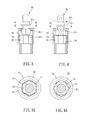
  • FIG. 3 is a cross-sectional drawing of the driving head-changeable tool in accordance with the preferable embodiment of the present invention.
  • FIG. 3A is a cross-sectional drawing along 3 A- 3 A in FIG. 3 ;
  • FIG. 4 is another cross-sectional drawing of the driving head-changeable tool in accordance with the preferable embodiment of the present invention.
  • FIG. 4A is a cross-sectional drawing along 4 A- 4 A in FIG. 4 ;
  • FIGS. 5 and 6 are cross-sectional drawings of the driving head-changeable tool in accordance with the preferable embodiment of the present invention in assembly;
  • FIG. 7 is a cross-sectional drawing along 7 - 7 in FIG. 5 ;
  • FIG. 8 is a cross-sectional drawing of the driving head-changeable tool in accordance with another preferable embodiment of the present invention.
  • FIGS. 9-11 are perspective drawings of the driving head-changeable tool in accordance with embodiments of the present invention with different driving heads.
  • a driving head-changeable tool in accordance with a preferred embodiment of the present invention comprises an outer sleeve 10 and an inner sleeve 20 .
  • the outer sleeve 10 defines a central axis 11 .
  • the outer sleeve 10 has an end peripheral edge 12 and a non-circular circumferential inner wall 13 (such as a hexagonal pillar).
  • the end peripheral edge 12 is formed with a plurality of corner portions 14 and a plurality of blocking flanges 15 located between the corner portions 14 .
  • a distance from the corner portion 14 to the central axis 11 is greater than a distance from the blocking flange 15 to the central axis 11 .
  • each of the blocking flanges 15 is flatly and straightly connected between the two corner portions 14 adjacent to each other. Compared with the two adjacent blocking flanges 15 , each of the corner portions 14 is invaginated radially in the end peripheral edge 12 .
  • the inner sleeve 20 has a non-circular circumferential outer wall 21 .
  • the non-circular circumferential outer wall 21 corresponds to the non-circular circumferential inner wall 13 in shape and in dimension.
  • the inner sleeve 20 is detachably sleeved by the outer sleeve 10 and has a first connecting end 22 along the central axis.
  • An inner wall of the first connecting end 22 is formed with a plurality of concaves 23 extending axially and a first end face 24 facing the blocking flanges 15 .
  • the non-circular circumferential inner and outer walls 13 , 21 are nonrotatably abutted against each other.
  • a distance from the concave 23 to the central axis 11 is smaller than a distance from the blocking flange 15 to the central axis 11 .
  • a driving head 30 is able to be inserted in the outer sleeve 10 and rotatable relative to the outer sleeve 10 .
  • each of the concaves 23 overlaps with one the blocking flange 15 (as shown in FIGS. 4 and 4A ).
  • the driving head 30 includes a first end 31 , and the first end 31 includes a plurality of abutting corner portions 311 axially extending and formed on a circumferential surface and a second end surface 312 .
  • a maximum distance from the abutting corner portions 311 to the central axis 11 is smaller than a distance from the blocking flange 15 to the central axis 11 .
  • a distance from a maximum outer diameter of the abutting corner portions 311 to the second end surface 312 is equal to or smaller than the predetermined distance.
  • the first end 31 is formed with a polygonal ball-shaped head 313 and a radial protruding flange 314 .
  • a necking shape is formed between the polygonal ball-shaped head 313 and the radial protruding flange 314 .
  • a second end 315 of the driving head 30 is formed with a quadrilateral connecting head 316 .
  • the quadrilateral connecting head 316 is for connecting with a driving device, a switching head, a screw driver or a driller and so on.
  • the first end 31 is detachably inserted in the first connecting end 22 .
  • each of the abutting corner portions 311 rotates to correspond to one the concave 23
  • each of the abutting corner portions 311 is blockably received within the corresponding concave 23 .
  • the first end face 24 and the blocking flanges 15 come close to each other, the first end 31 of the driving head 30 is blocked in the first connecting end 22 by the blocking flanges 15 (as shown in FIGS. 4 and 4A ).
  • the driving head-changeable tool further includes an abutting mechanism 40 .
  • the abutting mechanism 40 includes an abutting body 41 retractably disposed protrusively on the non-circular circumferential inner wall 13 or the non-circular circumferential outer wall 21 , and the abutting body 41 abuts against between the non-circular circumferential inner and outer walls 13 , 21 .
  • the abutting mechanism 40 further includes an axial extending slot 42 formed on one of the non-circular circumferential inner and outer walls 13 , 21 .
  • the other of the non-circular circumferential inner and outer walls 13 , 21 is provided with the abutting body 41 , and the abutting body 41 is movably disposed in the axial extending slot 42 .
  • the axial extending slot 42 preferably includes at least one enlarged and recessed positioning slot portion.
  • the at least one positioning slot portion includes a first positioning slot portion 43 close to the end peripheral edge 12 and a second positioning slot portion 44 far away from the end peripheral edge 12 .
  • the distance between the first end face 24 and the end peripheral edge 12 is equal to or greater than the predetermined distance.
  • the outer sleeve 10 and the inner sleeve 20 are positioned with each other on a predetermined position by the abutting mechanism 40 .
  • an inner wall of the first connecting end 22 of the inner sleeve 20 is formed with a stepped surface 25 facing the first end 31 of the driving head 30 .
  • the radial protruding flange 314 abuts against the end peripheral edge 12
  • the second end surface 312 of the first end 31 abuts against the stepped surface 25 .
  • the driving head 30 is assembled with the inner sleeve 20 and the outer sleeve 10 solidly, and it is durable and can be applied to such as dynamic impact tools.
  • the driving head-changeable tool includes an outer sleeve 10 and an inner sleeve 20 .
  • the outer sleeve 10 defines a central axis 11 and has an end peripheral edge 12 and a non-circular circumferential inner wall 13 .
  • the end peripheral edge 12 is formed with corner portions and a plurality of blocking flanges 15 located between the corner portions 14 .
  • a distance from the corner portion 14 to the central axis 11 is greater than a distance from the blocking flange 15 to the central axis 11 .
  • a first end 31 of a driving head 30 is received in the outer sleeve 10 .
  • the first end 31 is formed with a plurality of abutting corner portions 311 extending axially on a circumferential surface. A maximum distance from the abutting corner portions 311 to the central axis 11 is smaller than a distance from the blocking flange 15 to the central axis 11 . As viewed in an axial direction, each of the abutting corner portions 311 is opposite to one the blocking flange 15 .
  • the inner sleeve 20 has a non-circular circumferential outer wall 21 and is detachably sleeved by the outer sleeve 10 . The inner sleeve 20 has a first connecting end 22 along the central axis.
  • An inner wall of the first connecting end 22 is formed with a plurality of concaves 23 extending axially. A distance from the concave 23 to the central axis 11 is smaller than a distance from the blocking flange 15 to the central axis 11 . As viewed in an axial direction, each concave 23 overlaps with one the blocking flange 15 .
  • the concaves 23 correspond to the abutting corner portions 311 and the first connecting end 22 inserted on the first end 31 of the driving head. Each of the abutting corner portions 311 is received in the corresponding concave 23 and the non-circular circumferential inner and outer walls 13 , 21 are nonrotatably abutted against each other.
  • the driving head-changeable tool further includes an abutting mechanism 40 .
  • the abutting mechanism 40 includes an abutting body 41 retractably disposed protrusively on the non-circular circumferential inner wall 13 or the non-circular circumferential outer wall 21 , and the abutting body 41 abuts against between the non-circular circumferential inner and outer walls 13 , 21 .
  • the abutting mechanism 40 has the same structure as described above, and it will not be described.
  • a distance between the first end face 24 and the end peripheral edge 12 is equal to or greater than the predetermined distance, and the first end 31 of the driving head is able to be inserted in the first connecting end 22 of the inner sleeve 20 and rotatable so that each of the abutting corner portions 311 corresponds to each of the concaves 23 and each of the blocking flanges 15 .
  • each of the abutting corner portions 311 rotates to correspond to one the concave 23 , each of the abutting corner portions 311 is blockably received within the corresponding concave 23 .
  • the first end 31 of the driving head is blocked in the first connecting end 22 by the blocking flanges 15 .
  • the driving head is rotatable relatively to the inner sleeve and the outer sleeve via the polygonal ball-shaped head.
  • the first end 31 of the driving head is received in the outer sleeve 10 , and each of the abutting corner portions 311 is opposite to one the blocking flange 15 (as shown in FIG. 8 ), and then the outer sleeve 10 and the inner sleeve 20 are inserted to each other.
  • the first end 31 of the driving head is blocked in the first connecting end 22 by the blocking flange 15 (as shown in FIGS. 5 and 6 ).
  • the driving head can be a type such as polygonal ball-shaped as described above and a driving head 30 a of a driving head-changeable tool as shown in FIG. 9 .
  • the second end of the driving head 30 a is formed with a hexagonal pillar 31 a (can be used as a hexagonal wrench).
  • FIG. 10 it shows a driving head 30 b in an embodiment of the driving head-changeable tool.
  • the second end of the driving head 30 b is formed with a sleeve 31 b , and it can be other types such as a screw driver or a driller and so on.
  • a driving head 30 c is formed with a straight polygonal rod 32 c on a first end 31 c . As viewed in an axial direction, when each of abutting corner portions 33 c of the straight polygonal rod 32 c overlaps one the blocking flange, it prevents the driving head 30 c from prolapsing.
  • the outer sleeve and the inner sleeve are inserted to each other through non-circular circumferential walls so that each blocking flange blocks each abutting corner portion of a driving head and it prevents that the driving head prolapses from the inner sleeve, and the driving head is convenient to change. Fewer members are needed, and a structure is simple and easy for assembling.
  • outer sleeve and the inner sleeve are assembled to each other through non-circular circumferential walls so that it has a structure with better strength.
  • the structure is durable under high-speed or/and high-torque working.
  • a driving head of driving head-changeable tool in this prevention is rotatable relatively to an inner sleeve and an outer sleeve so that the driving head can be used in some work places with limited space to tighten/release fasteners (such as screws or bolts).
  • each abutting corner portion of the driving head is blocked by the corresponding blocking flange so that it prevents the driving head from prolapsing and helps to work effectively and securely.

Landscapes

  • Engineering & Computer Science (AREA)
  • Mechanical Engineering (AREA)
  • Portable Nailing Machines And Staplers (AREA)

Abstract

A driving head-changeable tool is provided, comprising an outer sleeve and an inner sleeve. The outer sleeve has an end peripheral edge and a non-circular circumferential inner wall. The end peripheral edge is formed with corner portions and blocking flanges. The inner sleeve has a non-circular circumferential outer wall. The inner sleeve is rotatably sleeved by the outer sleeve and has a first connecting end along a central axis. An inner wall of the first connecting end is formed with concaves extending axially. The non-circular circumferential inner and outer walls are nonrotatably abutted against each other. As viewed in an axial direction, each concave overlaps with one the blocking flange. When a driving head is inserted in the inner sleeve and the outer sleeve and the inner sleeve come close to each other, the driving head is blocked by the blocking flanges.

Description

BACKGROUND OF THE INVENTION
1. Field of the Invention
The present invention relates to a driving head, and more particularly to a driving head-changeable tool.
2. Description of the Prior Art
In prior art of two-part form of connecting head, a polygonal ball-shaped head of a support rod is received in a receiving slot of a working head. And the receiving slot corresponds to the polygonal ball-shaped head in shape. The support rod is assembled and fixed with the working head through a connecting structure. The support rod is pulled out and rotates relatively to the working head. This kind of connecting head is disclosed in TW566284 and TWM357344.
A structure as described in the TW566284, having an inner wall of the receiving slot formed as polygonal-shaped and contacting with the polygonal ball-shaped head through surfaces. When the support rod is driven to rotate relatively to the working head by an electrical driving device with a high speed, the receiving slot and the polygonal ball-shaped head are easily blocked because of friction between each other. Also, the electrical device and the two-part form of connecting head are damaged. Furthermore, the friction also causes energy loss and makes work efficiency worse.
A structure as described in the TWM357344, having a lateral wall of the receiving slot formed with protruding flanges corresponding to the polygonal ball-shaped head. The protruding flanges are equal spaced-apart and longitudinally disposed on the lateral wall. A number of the protruding flanges corresponds to the polygonal ball-shaped head. Each of the protruding flanges includes a camber surface for contacting with the polygonal ball-shaped head. The support rod and the working head are linking-up in rotation and it improves the disadvantages in the TW566284.
However, either TW566284 or TWM357344 has a structure which is unformed with blocking flanges to block corner portions of the polygonal ball-shaped head. The driving head easily prolapses, and it stops the work, reduces work efficiency and causes secure problems.
The present invention has arisen to mitigate and/or obviate the afore-described disadvantages.
SUMMARY OF THE INVENTION
The primary object of the present invention is to provide a driving head-changeable tool, having a structure for preventing the driving head from prolapsing and convenient to change the driving head. The driving head can rotate and has better work efficiency. The structure also has fewer members, and the structure is simple and easy for assembling.
To achieve the above object, a driving head-changeable tool is provided, comprising an outer sleeve and an inner sleeve. The outer sleeve defines a central axis and has an end peripheral edge and a non-circular circumferential inner wall. The end peripheral edge is formed with a plurality of corner portions and a plurality of blocking flanges located between the corner portions. A distance from the corner portion to the central axis is greater than a distance from the blocking flange to the central axis. The inner sleeve has a non-circular circumferential outer wall, is detachably sleeved by the outer sleeve and has a first connecting end along the central axis. An inner wall of the first connecting end is formed with a plurality of concaves extending axially and a first end face facing the blocking flanges. The non-circular circumferential inner and outer walls are nonrotatably abutted against each other. A distance from the concave to the central axis is smaller than a distance from the blocking flange to the central axis. As viewed in an axial direction, each concave overlaps with one the blocking flange. When a distance between the first end face and the end peripheral edge is equal to or greater than a predetermined distance, a driving head is able to be inserted in the outer sleeve and rotatable relative to the outer sleeve. The driving head includes a first end. The first end includes a plurality of abutting corner portions extending axially and formed on a circumferential surface and a second end surface. A maximum distance from the abutting corner portions to the central axis is smaller than a distance from the blocking flange to the central axis. A distance from a maximum outer diameter of the abutting corner portions to the second end surface is equal to or smaller than the predetermined distance. The first end is detachably inserted in the first connecting end. When each of the abutting corner portions rotates to correspond to one the concave, each of the abutting corner portions is blockably received within the corresponding concave. And when the first end face and the blocking flanges come close to each other, the first end of the driving head is blocked in the first connecting end by the blocking flanges.
A driving head-changeable tool is also provided, comprising an outer sleeve and an inner sleeve. The outer sleeve defines a central axis and has an end peripheral edge and a non-circular circumferential inner wall. The end peripheral edge is formed with a plurality of corner portions and a plurality of blocking flanges located between the corner portions. A distance from the corner portion to the central axis is greater than a distance from the blocking flange to the central axis. A first end of a driving head is received in the outer sleeve. The first end is formed with a plurality of abutting corner portions extending axially on a circumferential surface. A maximum distance from the abutting corner portions to the central axis is smaller than a distance from the blocking flange to the central axis. As viewed in an axial direction, each of the abutting corner portions is opposite to one the blocking flange. An inner sleeve has a non-circular circumferential outer wall and is detachably sleeved by the outer sleeve. The inner sleeve has a first connecting end along the central axis. An inner wall of the first connecting end is formed with a plurality of concaves extending axially. A distance from the concave to the central axis is smaller than a distance from the blocking flange to the central axis. As viewed in an axial direction, each concave overlaps with one the blocking flange. The concaves correspond to the abutting corner portions and the first connecting end is inserted on the first end of the driving head. Each of the abutting corner portions is received in the corresponding concave and the non-circular circumferential inner and outer walls are nonrotatably abutted against each other. When the first connecting end and the blocking flanges come close to each other, the first end of the driving head is blocked in the first connecting end by the blocking flanges.
BRIEF DESCRIPTION OF THE DRAWINGS
FIG. 1 is a three-dimensional drawing of a driving head-changeable tool in accordance with a preferable embodiment of the present invention;
FIG. 2 is a breakdown drawing of the driving head-changeable tool in accordance with the preferable embodiment of the present invention;
FIG. 3 is a cross-sectional drawing of the driving head-changeable tool in accordance with the preferable embodiment of the present invention;
FIG. 3A is a cross-sectional drawing along 3A-3A in FIG. 3;
FIG. 4 is another cross-sectional drawing of the driving head-changeable tool in accordance with the preferable embodiment of the present invention;
FIG. 4A is a cross-sectional drawing along 4A-4A in FIG. 4;
FIGS. 5 and 6 are cross-sectional drawings of the driving head-changeable tool in accordance with the preferable embodiment of the present invention in assembly;
FIG. 7 is a cross-sectional drawing along 7-7 in FIG. 5;
FIG. 8 is a cross-sectional drawing of the driving head-changeable tool in accordance with another preferable embodiment of the present invention;
FIGS. 9-11 are perspective drawings of the driving head-changeable tool in accordance with embodiments of the present invention with different driving heads.
DETAILED DESCRIPTION OF THE PREFERRED EMBODIMENTS
The present invention will be clearer from the following description when viewed together with the accompanying drawings, which show, for purpose of illustrations only, the preferred embodiment in accordance with the present invention.
Referring to FIGS. 1-3, 3A, 4 and 4A, a driving head-changeable tool in accordance with a preferred embodiment of the present invention comprises an outer sleeve 10 and an inner sleeve 20.
The outer sleeve 10 defines a central axis 11. The outer sleeve 10 has an end peripheral edge 12 and a non-circular circumferential inner wall 13 (such as a hexagonal pillar). The end peripheral edge 12 is formed with a plurality of corner portions 14 and a plurality of blocking flanges 15 located between the corner portions 14. A distance from the corner portion 14 to the central axis 11 is greater than a distance from the blocking flange 15 to the central axis 11. Moreover, each of the blocking flanges 15 is flatly and straightly connected between the two corner portions 14 adjacent to each other. Compared with the two adjacent blocking flanges 15, each of the corner portions 14 is invaginated radially in the end peripheral edge 12.
The inner sleeve 20 has a non-circular circumferential outer wall 21. Practically, the non-circular circumferential outer wall 21 corresponds to the non-circular circumferential inner wall 13 in shape and in dimension. The inner sleeve 20 is detachably sleeved by the outer sleeve 10 and has a first connecting end 22 along the central axis. An inner wall of the first connecting end 22 is formed with a plurality of concaves 23 extending axially and a first end face 24 facing the blocking flanges 15. The non-circular circumferential inner and outer walls 13, 21 are nonrotatably abutted against each other. A distance from the concave 23 to the central axis 11 is smaller than a distance from the blocking flange 15 to the central axis 11. When a distance between the first end face 24 and the end peripheral edge 12 is equal to or greater than a predetermined distance, a driving head 30 is able to be inserted in the outer sleeve 10 and rotatable relative to the outer sleeve 10. As viewed in an axial direction, each of the concaves 23 overlaps with one the blocking flange 15 (as shown in FIGS. 4 and 4A).
The driving head 30 includes a first end 31, and the first end 31 includes a plurality of abutting corner portions 311 axially extending and formed on a circumferential surface and a second end surface 312. A maximum distance from the abutting corner portions 311 to the central axis 11 is smaller than a distance from the blocking flange 15 to the central axis 11. A distance from a maximum outer diameter of the abutting corner portions 311 to the second end surface 312 is equal to or smaller than the predetermined distance. In the present embodiment, the first end 31 is formed with a polygonal ball-shaped head 313 and a radial protruding flange 314. A necking shape is formed between the polygonal ball-shaped head 313 and the radial protruding flange 314. A second end 315 of the driving head 30 is formed with a quadrilateral connecting head 316. The quadrilateral connecting head 316 is for connecting with a driving device, a switching head, a screw driver or a driller and so on.
The first end 31 is detachably inserted in the first connecting end 22. When each of the abutting corner portions 311 rotates to correspond to one the concave 23, each of the abutting corner portions 311 is blockably received within the corresponding concave 23. When the first end face 24 and the blocking flanges 15 come close to each other, the first end 31 of the driving head 30 is blocked in the first connecting end 22 by the blocking flanges 15 (as shown in FIGS. 4 and 4A).
The driving head-changeable tool further includes an abutting mechanism 40. The abutting mechanism 40 includes an abutting body 41 retractably disposed protrusively on the non-circular circumferential inner wall 13 or the non-circular circumferential outer wall 21, and the abutting body 41 abuts against between the non-circular circumferential inner and outer walls 13, 21. Preferably, the abutting mechanism 40 further includes an axial extending slot 42 formed on one of the non-circular circumferential inner and outer walls 13, 21. The other of the non-circular circumferential inner and outer walls 13, 21 is provided with the abutting body 41, and the abutting body 41 is movably disposed in the axial extending slot 42. The axial extending slot 42 preferably includes at least one enlarged and recessed positioning slot portion. The at least one positioning slot portion includes a first positioning slot portion 43 close to the end peripheral edge 12 and a second positioning slot portion 44 far away from the end peripheral edge 12. When the abutting body 41 abuts against the first positioning slot portion 43, a distance between the first end face 24 and the end peripheral edge 12 is smaller than the predetermined distance. When the abutting body 41 abuts against the second positioning slot portion 44, the distance between the first end face 24 and the end peripheral edge 12 is equal to or greater than the predetermined distance. The outer sleeve 10 and the inner sleeve 20 are positioned with each other on a predetermined position by the abutting mechanism 40.
Preferably, an inner wall of the first connecting end 22 of the inner sleeve 20 is formed with a stepped surface 25 facing the first end 31 of the driving head 30. When the radial protruding flange 314 abuts against the end peripheral edge 12, the second end surface 312 of the first end 31 abuts against the stepped surface 25. The driving head 30 is assembled with the inner sleeve 20 and the outer sleeve 10 solidly, and it is durable and can be applied to such as dynamic impact tools.
Referring to FIG. 8 and with further reference to FIGS. 2 and 5, in another embodiment, wherein the same members as described above are represented with the same symbols, the driving head-changeable tool includes an outer sleeve 10 and an inner sleeve 20. The outer sleeve 10 defines a central axis 11 and has an end peripheral edge 12 and a non-circular circumferential inner wall 13. The end peripheral edge 12 is formed with corner portions and a plurality of blocking flanges 15 located between the corner portions 14. A distance from the corner portion 14 to the central axis 11 is greater than a distance from the blocking flange 15 to the central axis 11. A first end 31 of a driving head 30 is received in the outer sleeve 10. The first end 31 is formed with a plurality of abutting corner portions 311 extending axially on a circumferential surface. A maximum distance from the abutting corner portions 311 to the central axis 11 is smaller than a distance from the blocking flange 15 to the central axis 11. As viewed in an axial direction, each of the abutting corner portions 311 is opposite to one the blocking flange 15. The inner sleeve 20 has a non-circular circumferential outer wall 21 and is detachably sleeved by the outer sleeve 10. The inner sleeve 20 has a first connecting end 22 along the central axis. An inner wall of the first connecting end 22 is formed with a plurality of concaves 23 extending axially. A distance from the concave 23 to the central axis 11 is smaller than a distance from the blocking flange 15 to the central axis 11. As viewed in an axial direction, each concave 23 overlaps with one the blocking flange 15. The concaves 23 correspond to the abutting corner portions 311 and the first connecting end 22 inserted on the first end 31 of the driving head. Each of the abutting corner portions 311 is received in the corresponding concave 23 and the non-circular circumferential inner and outer walls 13, 21 are nonrotatably abutted against each other. When the first connecting end 22 and the blocking flanges 15 come close to each other, the first end 31 of the driving head is blocked in the first connecting end 22 by the blocking flanges 15.
The driving head-changeable tool further includes an abutting mechanism 40. The abutting mechanism 40 includes an abutting body 41 retractably disposed protrusively on the non-circular circumferential inner wall 13 or the non-circular circumferential outer wall 21, and the abutting body 41 abuts against between the non-circular circumferential inner and outer walls 13, 21. The abutting mechanism 40 has the same structure as described above, and it will not be described.
Referring to FIGS. 3-6, practically, a distance between the first end face 24 and the end peripheral edge 12 is equal to or greater than the predetermined distance, and the first end 31 of the driving head is able to be inserted in the first connecting end 22 of the inner sleeve 20 and rotatable so that each of the abutting corner portions 311 corresponds to each of the concaves 23 and each of the blocking flanges 15. When each of the abutting corner portions 311 rotates to correspond to one the concave 23, each of the abutting corner portions 311 is blockably received within the corresponding concave 23. When the outer sleeve 10 and the inner sleeve 20 come close to each other, the first end 31 of the driving head is blocked in the first connecting end 22 by the blocking flanges 15. When the radial protruding flange unabuts against the end peripheral edge, the driving head is rotatable relatively to the inner sleeve and the outer sleeve via the polygonal ball-shaped head. Or the first end 31 of the driving head is received in the outer sleeve 10, and each of the abutting corner portions 311 is opposite to one the blocking flange 15 (as shown in FIG. 8), and then the outer sleeve 10 and the inner sleeve 20 are inserted to each other. The first end 31 of the driving head is blocked in the first connecting end 22 by the blocking flange 15 (as shown in FIGS. 5 and 6).
The driving head can be a type such as polygonal ball-shaped as described above and a driving head 30 a of a driving head-changeable tool as shown in FIG. 9. The second end of the driving head 30 a is formed with a hexagonal pillar 31 a (can be used as a hexagonal wrench). Referring to FIG. 10, it shows a driving head 30 b in an embodiment of the driving head-changeable tool. The second end of the driving head 30 b is formed with a sleeve 31 b, and it can be other types such as a screw driver or a driller and so on. Referring to FIG. 11, a driving head 30 c is formed with a straight polygonal rod 32 c on a first end 31 c. As viewed in an axial direction, when each of abutting corner portions 33 c of the straight polygonal rod 32 c overlaps one the blocking flange, it prevents the driving head 30 c from prolapsing.
As a conclusion, the outer sleeve and the inner sleeve are inserted to each other through non-circular circumferential walls so that each blocking flange blocks each abutting corner portion of a driving head and it prevents that the driving head prolapses from the inner sleeve, and the driving head is convenient to change. Fewer members are needed, and a structure is simple and easy for assembling.
Besides, the outer sleeve and the inner sleeve are assembled to each other through non-circular circumferential walls so that it has a structure with better strength. The structure is durable under high-speed or/and high-torque working.
Furthermore, a driving head of driving head-changeable tool in this prevention is rotatable relatively to an inner sleeve and an outer sleeve so that the driving head can be used in some work places with limited space to tighten/release fasteners (such as screws or bolts). Moreover, each abutting corner portion of the driving head is blocked by the corresponding blocking flange so that it prevents the driving head from prolapsing and helps to work effectively and securely.
While we have shown and described various embodiments in accordance with the present invention, it should be clear to those skilled in the art that further embodiments may be made without departing from the scope of the present invention.

Claims (12)

What is claimed is:
1. A driving head-changeable tool, comprising:
an outer sleeve, defining a central axis, having an end peripheral edge and a non-circular circumferential inner wall, the end peripheral edge formed with a plurality of corner portion and a plurality of blocking flange located between the corner portions, a distance from the corner portion to the central axis greater than a distance from the blocking flange to the central axis;
an inner sleeve, having a non-circular circumferential outer wall, detachably sleeved by the outer sleeve, having a first connecting end along the central axis, an inner wall of the first connecting end formed with a plurality of concaves extending axially and a first end face facing the blocking flanges, the non-circular circumferential inner and outer walls nonrotatably abutted against each other, a distance from the concave to the central axis smaller than the distance from the blocking flange to the central axis, as viewed in an axial direction, each concave overlapping with one the blocking flange, when a distance between the first end face and the end peripheral edge equal to or greater than a predetermined distance, a driving head is able to be inserted in the outer sleeve and rotatable relative to the outer sleeve;
wherein the driving head includes a first end, the first end includes a plurality of abutting corner portions extending axially and formed on a circumferential surface and a second end surface, a maximum distance from the abutting corner portions to the central axis is smaller than the distance from the blocking flange to the central axis, a distance from a maximum outer diameter of the abutting corner portions to the second end surface is equal to or smaller than the predetermined distance, the first end is detachably inserted in the first connecting end, when each of the abutting corner portions rotates to correspond to one the concave, each of the abutting corner portions is blockably received within the corresponding concave, and when the first end and the blocking flanges come close to each other, the first end of the driving head is blocked in the first connecting end by the blocking flanges.
2. The driving head-changeable tool as claimed in claim 1, further including an abutting mechanism, the abutting mechanism includes an abutting body retractably disposed protrusively on the non-circular circumferential inner wall or the non-circular circumferential outer wall, and the abutting body abuts against between the non-circular circumferential inner and outer walls.
3. The driving head-changeable tool as claimed in claim 2, wherein the abutting mechanism further includes an axial extending slot formed on either of the non-circular circumferential inner and outer walls, the other of the non-circular circumferential inner and outer walls is provided with the abutting body, and the abutting body is movably disposed on the axial extending slot.
4. The driving head-changeable tool as claimed in claim 3, wherein the axial extending slot further includes at least one enlarged and recessed positioning slot portion.
5. The driving head-changeable tool as claimed in claim 4, wherein the at least one positioning slot portion includes a first positioning slot portion close to the end peripheral edge and a second positioning slot portion far away from the end peripheral edge, when the abutting body abuts against the first positioning slot portion, a distance between the first end face and the end peripheral edge is smaller than the predetermined distance, when the abutting body abuts against the second positioning slot portion, the distance between the first end face and the end peripheral edge is equal to or greater than the predetermined distance.
6. The driving head-changeable tool as claimed in claim 1, wherein the first end is formed with a polygonal ball-shaped head and a radial protruding flange, when the radial protruding flange abuts against the end peripheral edge, the driving head is restrainedly positioned by the inner sleeve and the outer sleeve, when the radial protruding flange unabuts against the end peripheral edge, the driving head is rotatable relatively to the inner sleeve and the outer sleeve via the polygonal ball-shaped head.
7. The driving head-changeable tool as claimed in claim 1, wherein the first end is formed with a straight polygonal rod.
8. A driving head-changeable tool is provided, comprising:
an outer sleeve, defining a central axis, having an end peripheral edge and a non-circular circumferential inner wall, the end peripheral edge formed with a plurality of corner portion and a plurality of blocking flange located between the corner portions, a distance from the corner portion to the central axis greater than a distance from the blocking flange to the central axis, a first end of a driving head received in the outer sleeve, the first end formed with a plurality of abutting corner portions extending axially on a circumferential surface, a maximum distance from the abutting corner portions to the central axis smaller than a distance from the blocking flange to the central axis, as viewed in an axial direction, each of the abutting corner portions opposite to one the blocking flange;
an inner sleeve, having a non-circular circumferential outer wall, detachably sleeved by the outer sleeve, having a first connecting end along the central axis, an inner wall of the first connecting end formed with a plurality of concaves extending axially, a distance from the concave to the central axis smaller than the distance from the blocking flange to the central axis, as viewed in an axial direction, each concave overlapping with one the blocking flange, the concaves corresponding to the abutting corner portions and the first connecting end inserted on the first end of the driving head, each of the abutting corner portions received in the corresponding concave and the non-circular circumferential inner and outer walls nonrotatably abutted against each other;
wherein when the first connecting end and the blocking flanges come close to each other, the first end of the driving head is blocked in the first connecting end by the blocking flanges.
9. The driving head-changeable tool as claimed in claim 8, further including an abutting mechanism, the abutting mechanism includes an abutting body retractably disposed protrusively on the non-circular circumferential inner wall or the non-circular circumferential outer wall, and the abutting body abuts against between the non-circular circumferential inner and outer walls.
10. The driving head-changeable tool as claimed in claim 8, wherein the first end is formed with a polygonal ball-shaped head and a radial protruding flange, when the radial protruding flange abuts against the end peripheral edge, the driving head is restrainedly positioned by the inner sleeve and the outer sleeve, when the radial protruding flange unabuts against the end peripheral edge, the driving head is rotatable relatively to the inner sleeve and the outer sleeve via the polygonal ball-shaped head.
11. The driving head-changeable tool as claimed in claim 10, wherein an inner wall of the first connecting end is formed with a stepped surface facing the first end of the driving head, when the radial protruding flange abuts against the end peripheral edge, an end surface of the first end abuts against the stepped surface.
12. The driving head-changeable tool as claimed in claim 8, wherein the first end is formed with a straight polygonal rod.
US14/316,793 2014-06-26 2014-06-26 Driving head-changeable tool Active 2034-08-07 US9205543B1 (en)

Priority Applications (1)

Application Number Priority Date Filing Date Title
US14/316,793 US9205543B1 (en) 2014-06-26 2014-06-26 Driving head-changeable tool

Applications Claiming Priority (1)

Application Number Priority Date Filing Date Title
US14/316,793 US9205543B1 (en) 2014-06-26 2014-06-26 Driving head-changeable tool

Publications (2)

Publication Number Publication Date
US9205543B1 true US9205543B1 (en) 2015-12-08
US20150375377A1 US20150375377A1 (en) 2015-12-31

Family

ID=54708172

Family Applications (1)

Application Number Title Priority Date Filing Date
US14/316,793 Active 2034-08-07 US9205543B1 (en) 2014-06-26 2014-06-26 Driving head-changeable tool

Country Status (1)

Country Link
US (1) US9205543B1 (en)

Cited By (8)

* Cited by examiner, † Cited by third party
Publication number Priority date Publication date Assignee Title
US20160052111A1 (en) * 2014-08-21 2016-02-25 Yuan Li Hsing Industrial Co., Ltd. Driving head-changeable tool and sleeve assembly thereof
US20160138657A1 (en) * 2014-04-17 2016-05-19 Yuan Li Hsing Industrial Co., Ltd. Driving head-changeable tool
US20170348832A1 (en) * 2016-06-06 2017-12-07 Hsin-Hung Yang Tool connector assembly
US20180185994A1 (en) * 2017-01-05 2018-07-05 Hong Ann Tool Industries Co., Ltd. Driving Tool with Pivotal Driving End
US10391616B1 (en) * 2017-01-26 2019-08-27 Jore Corporation Tool connector assembly
US11067116B2 (en) * 2018-09-10 2021-07-20 Federal-Mogul Motorparts Llc Low torque ball socket assembly
US20220024009A1 (en) * 2020-07-23 2022-01-27 William C. Summers System and method for lug nut cap cover removal tool
US20240025021A1 (en) * 2021-09-14 2024-01-25 Tien-I Industrial Co., Ltd. Universal joint

Families Citing this family (1)

* Cited by examiner, † Cited by third party
Publication number Priority date Publication date Assignee Title
RU174753U1 (en) * 2016-11-17 2017-10-31 Общество с ограниченной ответственностью "Первоуральский Автоагрегатный завод" Insert for mounting and dismounting a threaded fastener

Citations (5)

* Cited by examiner, † Cited by third party
Publication number Priority date Publication date Assignee Title
US6321855B1 (en) * 1994-12-29 2001-11-27 George Edward Barnes Anti-vibration adaptor
US7278342B1 (en) * 2006-03-21 2007-10-09 Sheng Ming Chang Tool connecting device
US7669860B2 (en) * 2006-07-27 2010-03-02 Hsin Ying Enterprise Co., Ltd. Tool retaining or connecting device
US7942426B2 (en) * 2006-07-12 2011-05-17 Black & Decker Inc. Pivotal/rigid accessories for power and hand tools
US8366339B2 (en) * 2009-03-29 2013-02-05 Hsiu-Nien Lin Two-section tool joint

Patent Citations (5)

* Cited by examiner, † Cited by third party
Publication number Priority date Publication date Assignee Title
US6321855B1 (en) * 1994-12-29 2001-11-27 George Edward Barnes Anti-vibration adaptor
US7278342B1 (en) * 2006-03-21 2007-10-09 Sheng Ming Chang Tool connecting device
US7942426B2 (en) * 2006-07-12 2011-05-17 Black & Decker Inc. Pivotal/rigid accessories for power and hand tools
US7669860B2 (en) * 2006-07-27 2010-03-02 Hsin Ying Enterprise Co., Ltd. Tool retaining or connecting device
US8366339B2 (en) * 2009-03-29 2013-02-05 Hsiu-Nien Lin Two-section tool joint

Cited By (13)

* Cited by examiner, † Cited by third party
Publication number Priority date Publication date Assignee Title
US20160138657A1 (en) * 2014-04-17 2016-05-19 Yuan Li Hsing Industrial Co., Ltd. Driving head-changeable tool
US9903419B2 (en) * 2014-04-17 2018-02-27 Yuan Li Hsing Industrial Co., Ltd. Driving head-changeable tool
US9776310B2 (en) * 2014-08-21 2017-10-03 Yuan Li Hsing Industrial Co., Ltd. Driving head-changeable tool and sleeve assembly thereof
US20160052111A1 (en) * 2014-08-21 2016-02-25 Yuan Li Hsing Industrial Co., Ltd. Driving head-changeable tool and sleeve assembly thereof
US20170348832A1 (en) * 2016-06-06 2017-12-07 Hsin-Hung Yang Tool connector assembly
US10661416B2 (en) * 2017-01-05 2020-05-26 Hong Ann Tool Industries Co., Ltd. Driving tool with pivotal driving end
US20180185994A1 (en) * 2017-01-05 2018-07-05 Hong Ann Tool Industries Co., Ltd. Driving Tool with Pivotal Driving End
US10391616B1 (en) * 2017-01-26 2019-08-27 Jore Corporation Tool connector assembly
US11067116B2 (en) * 2018-09-10 2021-07-20 Federal-Mogul Motorparts Llc Low torque ball socket assembly
US20220024009A1 (en) * 2020-07-23 2022-01-27 William C. Summers System and method for lug nut cap cover removal tool
USD1025738S1 (en) 2020-07-23 2024-05-07 William C. Summers Lug nut removal tool
US20240025021A1 (en) * 2021-09-14 2024-01-25 Tien-I Industrial Co., Ltd. Universal joint
US12560197B2 (en) * 2021-09-14 2026-02-24 Tien-I Industrial Co., Ltd. Universal joint

Also Published As

Publication number Publication date
US20150375377A1 (en) 2015-12-31

Similar Documents

Publication Publication Date Title
US9205543B1 (en) Driving head-changeable tool
US8771091B1 (en) Two-torque-producing connecting rod assembly
US6688195B1 (en) Bi-directional ratchet wrench
US7115028B1 (en) Coupling structure for grinding members
US9782886B2 (en) Compact hand tool with sliding cover
US20160339564A1 (en) Screwdriver bit structure
US9027445B2 (en) Socket with a reinforced strength
US10099356B2 (en) Adjusting assembly of brake cylinder installation device
US9776310B2 (en) Driving head-changeable tool and sleeve assembly thereof
US20150273670A1 (en) Mounting structure for a hand tool
US20150306674A1 (en) Structure-improved clamping chuck
US20160059394A1 (en) Combination Including a Ratchet Wrench and a Driving Member
US10525571B2 (en) Screwdriver and ratchet mechanism thereof
US20170057063A1 (en) Insert bit
US9375829B2 (en) Tool head
US9133922B2 (en) Load adjustable ball screw device
US20060258275A1 (en) Holding apparatus for grinding members
US10377024B2 (en) Tool with quick-release drill bits
US20150305569A1 (en) Nut disassembling device
KR20170089540A (en) ratchet wrench
US20200122304A1 (en) Socket wrench
US8342064B2 (en) Ratchetable open-ended wrench
CN105014617B (en) Tool with replaceable driving head
US8720310B2 (en) Socket wrench with an energy-saving function
US20130133487A1 (en) Tool Head Structure

Legal Events

Date Code Title Description
AS Assignment

Owner name: YUAN LI HSING INDUSTRIAL CO., LTD., TAIWAN

Free format text: ASSIGNMENT OF ASSIGNORS INTEREST;ASSIGNORS:CHEN, HUI-CHIEN;CHEN, CHIA-YI;REEL/FRAME:033244/0078

Effective date: 20140625

STCF Information on status: patent grant

Free format text: PATENTED CASE

MAFP Maintenance fee payment

Free format text: PAYMENT OF MAINTENANCE FEE, 4TH YR, SMALL ENTITY (ORIGINAL EVENT CODE: M2551); ENTITY STATUS OF PATENT OWNER: SMALL ENTITY

Year of fee payment: 4

MAFP Maintenance fee payment

Free format text: PAYMENT OF MAINTENANCE FEE, 8TH YR, SMALL ENTITY (ORIGINAL EVENT CODE: M2552); ENTITY STATUS OF PATENT OWNER: SMALL ENTITY

Year of fee payment: 8