US9196015B2 - Image processing apparatus, image processing method and image display system - Google Patents
Image processing apparatus, image processing method and image display system Download PDFInfo
- Publication number
- US9196015B2 US9196015B2 US13/572,897 US201213572897A US9196015B2 US 9196015 B2 US9196015 B2 US 9196015B2 US 201213572897 A US201213572897 A US 201213572897A US 9196015 B2 US9196015 B2 US 9196015B2
- Authority
- US
- United States
- Prior art keywords
- image
- image block
- block
- frame
- interpolated
- Prior art date
- Legal status (The legal status is an assumption and is not a legal conclusion. Google has not performed a legal analysis and makes no representation as to the accuracy of the status listed.)
- Active - Reinstated, expires
Links
Images


Classifications
-
- G—PHYSICS
- G06—COMPUTING OR CALCULATING; COUNTING
- G06T—IMAGE DATA PROCESSING OR GENERATION, IN GENERAL
- G06T3/00—Geometric image transformations in the plane of the image
- G06T3/40—Scaling of whole images or parts thereof, e.g. expanding or contracting
- G06T3/4007—Scaling of whole images or parts thereof, e.g. expanding or contracting based on interpolation, e.g. bilinear interpolation
-
- H—ELECTRICITY
- H04—ELECTRIC COMMUNICATION TECHNIQUE
- H04N—PICTORIAL COMMUNICATION, e.g. TELEVISION
- H04N19/00—Methods or arrangements for coding, decoding, compressing or decompressing digital video signals
- H04N19/10—Methods or arrangements for coding, decoding, compressing or decompressing digital video signals using adaptive coding
- H04N19/102—Methods or arrangements for coding, decoding, compressing or decompressing digital video signals using adaptive coding characterised by the element, parameter or selection affected or controlled by the adaptive coding
- H04N19/103—Selection of coding mode or of prediction mode
- H04N19/105—Selection of the reference unit for prediction within a chosen coding or prediction mode, e.g. adaptive choice of position and number of pixels used for prediction
-
- H—ELECTRICITY
- H04—ELECTRIC COMMUNICATION TECHNIQUE
- H04N—PICTORIAL COMMUNICATION, e.g. TELEVISION
- H04N19/00—Methods or arrangements for coding, decoding, compressing or decompressing digital video signals
- H04N19/10—Methods or arrangements for coding, decoding, compressing or decompressing digital video signals using adaptive coding
- H04N19/134—Methods or arrangements for coding, decoding, compressing or decompressing digital video signals using adaptive coding characterised by the element, parameter or criterion affecting or controlling the adaptive coding
- H04N19/154—Measured or subjectively estimated visual quality after decoding, e.g. measurement of distortion
-
- H—ELECTRICITY
- H04—ELECTRIC COMMUNICATION TECHNIQUE
- H04N—PICTORIAL COMMUNICATION, e.g. TELEVISION
- H04N19/00—Methods or arrangements for coding, decoding, compressing or decompressing digital video signals
- H04N19/10—Methods or arrangements for coding, decoding, compressing or decompressing digital video signals using adaptive coding
- H04N19/169—Methods or arrangements for coding, decoding, compressing or decompressing digital video signals using adaptive coding characterised by the coding unit, i.e. the structural portion or semantic portion of the video signal being the object or the subject of the adaptive coding
- H04N19/17—Methods or arrangements for coding, decoding, compressing or decompressing digital video signals using adaptive coding characterised by the coding unit, i.e. the structural portion or semantic portion of the video signal being the object or the subject of the adaptive coding the unit being an image region, e.g. an object
- H04N19/176—Methods or arrangements for coding, decoding, compressing or decompressing digital video signals using adaptive coding characterised by the coding unit, i.e. the structural portion or semantic portion of the video signal being the object or the subject of the adaptive coding the unit being an image region, e.g. an object the region being a block, e.g. a macroblock
-
- H—ELECTRICITY
- H04—ELECTRIC COMMUNICATION TECHNIQUE
- H04N—PICTORIAL COMMUNICATION, e.g. TELEVISION
- H04N19/00—Methods or arrangements for coding, decoding, compressing or decompressing digital video signals
- H04N19/50—Methods or arrangements for coding, decoding, compressing or decompressing digital video signals using predictive coding
- H04N19/587—Methods or arrangements for coding, decoding, compressing or decompressing digital video signals using predictive coding involving temporal sub-sampling or interpolation, e.g. decimation or subsequent interpolation of pictures in a video sequence
-
- H—ELECTRICITY
- H04—ELECTRIC COMMUNICATION TECHNIQUE
- H04N—PICTORIAL COMMUNICATION, e.g. TELEVISION
- H04N7/00—Television systems
- H04N7/01—Conversion of standards, e.g. involving analogue television standards or digital television standards processed at pixel level
- H04N7/0135—Conversion of standards, e.g. involving analogue television standards or digital television standards processed at pixel level involving interpolation processes
- H04N7/014—Conversion of standards, e.g. involving analogue television standards or digital television standards processed at pixel level involving interpolation processes involving the use of motion vectors
-
- H—ELECTRICITY
- H04—ELECTRIC COMMUNICATION TECHNIQUE
- H04N—PICTORIAL COMMUNICATION, e.g. TELEVISION
- H04N7/00—Television systems
- H04N7/01—Conversion of standards, e.g. involving analogue television standards or digital television standards processed at pixel level
- H04N7/0127—Conversion of standards, e.g. involving analogue television standards or digital television standards processed at pixel level by changing the field or frame frequency of the incoming video signal, e.g. frame rate converter
Definitions
- the invention relates in general to an image processing technique, and more particularly to a technique for generating an interpolated image.
- a frame frequency of dynamic images provided to an image display apparatus is lower than a frame update frequency of the image display apparatus itself.
- a frame frequency of an original dynamic image is 60 Hz
- a frame update frequency of an image display apparatus is 120 Hz.
- the image display apparatus usually generates 60 additional frames according to the original frame being updated 60 times per second, so that a frame presented to a monitor is 120 frames per second.
- a most simple yet rather crude approach to achieve the 120 frames per second frame rate is to play each original frame twice.
- Another common approach is generating and playing an interpolated frame between two successive original frames.
- an image display apparatus may also utilize a motion vector of two original frames to generate an interpolated image. Before generating an interpolated image according to a motion vector, the motion vector of two original frames must first be determined. In practice, an image processing apparatus may divide each frame into a plurality of blocks and estimate a motion vector of each block.
- the image processing apparatus compares a range of 32*32 pixels regarding the block B 1 as a center to determine which 8*8 block is the most similar to the block A 1 , thereby identifying the motion vector between the block A 1 and the block B 1 .
- an image processing apparatus generally cannot define an excessively large comparison range due to limitations of an allowed calculation period.
- the image processing apparatus may fail to accurately identify the motion vector between blocks A 1 and B 1 when searching the comparison range.
- the image processing apparatus is also likely to misjudge the motion vector between the two blocks A 1 and B 1 .
- a motion vector can be misjudged from time to time leading to an erroneous interpolation outcome.
- a sky image in an interpolated image may be inappropriately presented as a tree image that obviously does not fit into surroundings.
- human eyes are particularly sensitive to such abrupt changes that are thus easily spotted.
- an interpolated image as a new image is discarded when it is determined that a sum or all possible errors of an entire frame is higher than a threshold, and an original frame (e.g., frame A or frame B) is utilized as the new image; that is, it is in equivalence repeatedly playing the original frame.
- an image processing apparatus may be forced to give up other correct blocks with appropriate interpolation outcomes even when an entire interpolated frame only comprises a few blocks with severe errors, such that overall playback smoothness of the image is degraded due to repeatedly playing an original frame.
- the invention is directed to a solution that partially utilizes a motion vector as basis for a new frame. More specifically, an image processing apparatus, an image processing method and an image display system disclosed by the present invention determine whether an interpolated image generated according to a motion vector is to be adopted in a unit of blocks. When errors due to interpolation performed on the basis of motion vectors are likely to occur at certain blocks, the image processing apparatus, image processing method and image display system disclosed by the present invention only substitute the image blocks having possible errors with image blocks that are not interpolated on basis of motion vectors.
- a new frame generated by the image processing apparatus of the present invention possibly contains certain image blocks that are interpolated images generated according to motion vectors while other image blocks are substitutive images that are not generated according to motion vectors. Therefore, the approach of the present invention not only is capable of reducing a probability of presenting erroneous interpolation outcomes to a viewer but also contributes more ideal playback smoothness when displaying dynamic images.
- an image processing apparatus for generating an intermediate frame according to a previous frame and a next frame.
- the intermediate frame comprises a plurality of intermediate image blocks each corresponding to a motion vector.
- the image processing apparatus comprises a determining module and a selecting module. For each intermediate image block, the determining module determines whether an interpolated image generated according to the motion vector meets a correctness requirement.
- the selecting module selects the interpolated image to represent the intermediate image block when the interpolated image meets the correctness requirement, and selects a substitutive image different from the interpolated image to represent the intermediate image block when the interpolated image block fails to meet the correctness requirement.
- an image processing method for generating an intermediate frame according to a previous frame and a next frame comprises a plurality of intermediate image blocks each corresponding to a motion vector.
- the method comprises: according to the previous frame and the next frame, determining whether an interpolated image generated according to the motion vector meets a correctness requirement; selecting the interpolated image to represent the intermediate image block when the interpolated image meets the correctness requirement, or selecting a substitutive image different from the interpolated image to represent the intermediate image block when the interpolated image block fails to meet the correctness requirement.
- an image display system comprising a receiving module, a determining module, a selecting module and a display.
- the receiving module receives a previous frame and a next frame.
- An intermediate frame comprises a plurality of intermediate image blocks each corresponding to a motion vector.
- the determining module determines whether an interpolated image generated according to the motion vector meets a correctness requirement for each intermediate image block.
- the selecting module selects the interpolated image to represent the intermediate image block when the interpolated image meets the correctness requirement, and selects a substitutive image different from the interpolated image to represent the intermediate image block when the interpolated image block fails to meet the correctness requirement.
- the display sequentially displays the previous frame, the intermediate frame and the next frame.
- FIG. 1 is a block diagram of an image processing apparatus according to an embodiment of the present invention.
- FIG. 2 is an example of a determining module according to an embodiment of the present invention.
- FIG. 3 is an example showing relationships of a previous frame, a next frame and an intermediate frame.
- FIGS. 4 to 7 further illustrate block diagrams of hardware in the image processing apparatus for generating a substitutive image according to an embodiment of the present invention.
- FIG. 8 is a flowchart of an image processing method according to an embodiment of the present invention.
- FIG. 9 is a block diagram of an image display system according to an embodiment of the present invention.
- an image processing apparatus for generating at least one intermediate frame F according to a previous frame F 1 and a next frame F 2 is provided.
- the previous frame F 1 and the next frame F 2 may be two temporally successive frames in a video stream.
- an image processing apparatus 100 according to the embodiment comprises a determining module 12 and a selecting module 14 .
- the image processing apparatus 100 may be integrated in a system such as a television, a DVD player or a computer with an image playback function, or may be an independent device.
- the intermediate frame F comprises a plurality of intermediate image blocks, e.g., a plurality of non-overlapping image blocks of 8*8 pixels in size.
- Each intermediate image block corresponds to a motion vector, which is an unknown value at the time before any image processing is performed.
- the determining module 12 determines for each intermediate image block whether an interpolated image generated according to the motion vector meets a correctness requirement.
- FIG. 2 shows a determining module 12 according to an embodiment.
- the determining module 12 comprises a difference calculating unit 12 A and a comparing unit 12 B.
- the difference calculating unit 12 A calculates a minimum of a sum of absolute difference (SAD) of each intermediate image block according to the previous frame F 1 and the next frame F 2 . Operation details of the difference calculating unit 12 shall be described below.
- a planar coordinate of a center of an intermediate block B F with a size of 8*8 pixels of the intermediate frame F is (100, 100)
- a range with a size of 32*32 pixels also regarding the coordinate (100, 100) as its center is defined around the intermediate image block B F .
- the range R with a same planar position is also indicated in the previous frame F 1 and the next frame F 2 .
- the difference calculating unit 12 A may also search for the minimum SAD of the intermediate image block B F within the range R. For example, coordinates and sizes of a previous image block B F1 and a next image block B F2 are the same, and thus a motion vector between the two is regarded as (0, 0).
- the difference calculating unit 12 A may first identify the SAD of the previous image block B F1 and the next image block B F2 . That is, the difference calculating unit 12 A first identifies the SAD corresponding to the motion vector (0, 0), and then searches for the SAD corresponding to other different motion vectors within the range R.
- a comparison basis utilized by the difference calculating unit 12 A for calculating the SAD may be respective RGB grayscale or YUV values of the two images, but is not limited thereto.
- a range of the above motion vector is between ( ⁇ 15, ⁇ 15) to (16, 16), so that the difference calculating unit 12 A can provide a total of 1024 SADs, from which the difference calculating unit 12 A then selects a minimum SAD.
- an image block B FX and an image block B FY are the most similar, and thus an SAD identified according to the two image blocks B FX and B FY is the minimum SAD of the intermediate image block B F .
- a coordinate relation between the image blocks B FX and B FY may be regarded as a motion vector MV corresponding to the intermediate image block B F .
- the minimum SAD of the intermediate image block B F may serve as basis for determining whether an interpolated image generated according to the motion vector meets a correctness requirement.
- the comparing unit 12 B compares the minimum SAD with a threshold, and determines the interpolated image generated according to the motion vector fails to meet the correctness requirement when the minimum SAD of the intermediate image block B F is larger than the threshold.
- the comparing unit 12 B determines the interpolated image generated according to the motion vector MV satisfies the correctness requirement.
- a value of the threshold may be determined as desired, and is not limited to a predetermined value.
- the difference calculating unit 12 A respectively identifies the minimum SAD of the intermediate image blocks.
- the comparing unit 12 B may also determine whether the interpolated image generated according to the motion vector meets the correctness requirement. It is appreciated from the above description that, instead of having to practically identify the value of the motion vector, the determining module 12 is capable of determining whether the interpolated image generated according to the motion vector meets the correctness requirement once the minimum SAD of the intermediate image block is identified.
- the selecting module 14 selects the interpolated image generated according to the motion vector to represent the intermediate image block. Conversely, for the intermediate image block that fails to meet the correctness requirement based on the interpolated image generated according to the motion vector, the selecting module 14 selects a substitutive image different from the interpolated image to represent the intermediate image block. Referring to the image block B F in FIG. 3 , when the determining module 12 determines that the interpolated image generated according to the motion vector MV for representing the intermediate image block B F is likely faulty, the selecting module 14 does not select the interpolated image generated according to the motion vector MV to represent the image block B F .
- the image processing apparatus 100 determines whether to adopt an interpolated image generated according to a motion vector in a unit of blocks.
- the image processing apparatus of the present invention only replaces those image blocks but does not replace an entire intermediate frame with an original frame as in the prior art.
- a final intermediate frame F according to the present invention it is possible that certain blocks are interpolated images generated according to a motion vector while others are substitutive images different from the interpolated images generated according to a motion vector. Therefore, the approach of the present invention not only is capable of reducing a probability of presenting erroneous interpolation outcomes to a viewer but also contributes more ideal playback smoothness when displaying dynamic images.
- an image processing apparatus further comprises a memory 10 and a mixing module 16 according to another embodiment of the present invention.
- the memory 10 receives and temporarily stores the previous frame F 1 and the next frame F 2 , which are to be provided to a motion vector module 12 and the mixing module 16 for reference.
- each intermediate image block corresponds to a previous image block in the previous frame F 1 and a next image block in the next frame F 2 .
- the mixing module 16 mixes image data of the previous image block and the next image block according to a ratio to generate a substitutive image corresponding to the intermediate image block. For example, the ratio is 50%/50%; that is, the previous image block and the next image block are averaged.
- the approach of the present invention further enhances image display smoothness.
- an image processing apparatus comprises a mixing module 16 , an interpolating module 18 and a weighting module 20 according to an embodiment of the present invention.
- the mixing module 16 blends image data of the previous image block B F1 and the next image block B F2 to generate a mixed image.
- the difference calculating unit 12 A also determines the motion vector MV of the intermediate image block B F when searching for the minimum SAD of the intermediate image block B F .
- the motion vector MV is provided to the interpolating module 18 , which then generates an interpolated image for the intermediate frame B F according to the motion vector MV, the previous frame F 1 and the next frame F 2 .
- the weighting module 20 multiplies the image data of the mixed image by a second weighting W 2 and multiplies the image data of the interpolated image by a first weighting W 1 , and adds up the two products to generate a substitutive image of the target image block B F .
- a sum of the first weighting W 1 and the second weighting W 2 may be designed as a constant value.
- the first weighting W 1 is 0.7
- the second weighting W 2 is 0.3, with a total adding up to 1.
- functions of the selecting module 14 are realized by the weighting module 20 in this embodiment, and output signals of the comparing unit 12 B are provided to the weighting module 20 .
- the weighting module 20 sets the second weighting W 2 as 1 and the first weighting W 1 as 0. Conversely, when the comparing unit 12 B determines that the interpolated image generated by the interpolating module 18 according to the minimum SAD of the target image block B F meets the correctness requirement, the weighting module 20 sets the second weighting W 2 as 0 and the first weighting W 1 as 1.
- the first weighting W 1 and the second weighting W 2 may be designed to associate with conditions of neighboring image area of the intermediate image block.
- FIG. 6 shows an image processing apparatus further comprising a weighting determining module 22 according to yet another embodiment of the present invention. Apart from referencing a determination result of the comparing unit 12 B, the weighting module 22 also selectively associates the weightings with neighboring image area of the intermediate image block B F . Taking the intermediate image block B F for example, its neighboring image area may have a center as that of the intermediate image block B F , having a range of 16*16 pixels or 32*32 pixels, for example.
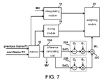
- FIG. 7 shows a detailed block diagram of the weighting determining module 22 .
- the weighting determining module 22 comprises a first operation unit 22 A, a second operation unit 22 B and a third operation unit 22 C.
- the neighboring image area of the intermediate image block B F is greater than and encompasses the intermediate block image B F .
- the difference calculating unit 14 A also assists in identifying the minimum SAD (to be referred to as SAD 2 ) of the neighboring image area.
- the first operation unit 22 A comprises a subtractor, which first subtracts a first compensation value O 1 from the first SAD SAD 1 .
- the first compensation value O 1 may be designed as the threshold adopted by the comparing unit 12 B in the abovementioned embodiment.
- An output of the subtractor is set to 0 when the first SAD SAD 1 is smaller than or equal to the first compensation value O 1 . That is to say, the output of the first operation unit 22 A is 0 when the first SAD SAD 1 is small enough to enable the corresponding interpolated image to meet the correctness requirement.
- the first weighting W 1 is lower to corresponding reduce the weighting of the mixed image.
- the first operation unit 22 A further comprises a multiplier, which multiplies a difference of subtracting the first compensation value O 1 from the first SAD SAD 1 by a first gain G 1 to generate a first operation value.
- the multiplier is for adjusting a size of the difference as required, e.g., for normalizing the difference.
- the second operation unit 22 B also comprises a subtractor and a multiplier, for respectively subtracting a compensation value O 2 from the second SAD SAD 2 and multiplying the difference by a second gain G 2 to generate a second operation value.
- the third operation unit 22 C adds the first operation value and the second operation value to generate the first weighting W 1 .
- functions of the subtractors may also be realized by the difference calculating unit 12 A.
- the first weighting W 1 corresponding to the averaged image becomes larger as the SAD 1 and/or the SAD 2 gets larger.
- the SAD 2 of the neighboring image area reflects a change tendency of images around the intermediate image block B F .
- a probability of an unsuitable interpolated image generated according the motion vector becomes higher as the SAD 2 of the neighboring area gets larger.
- it is possible that drastic changes are present in the neighboring image area (encompassing the intermediate image block B F ) while the SAD 1 of the intermediate image block B F itself remains below the threshold (i.e., the first compensation value O 1 ).
- the threshold i.e., the first compensation value O 1
- the image processing apparatus of the present invention may simultaneously consider conditions of at least two differently sized neighboring areas to provide different weightings of several differently ranged image areas, and then generate the first weighting W 1 by adding up all the weighting results.
- the image processing apparatus simultaneously consider ranges with sizes of 8*8 pixels, 16*16 pixels and 32*32 pixels to first respectively generate SAD 1 , SAD 2 and SAD 3 and then accordingly generate the first, second and third operation values. The first, second and third operation values are added to generate the first weighting W 1 .
- the first weighting W 1 is forwarded to the weighting module 20 to serve as a multiplier of the interpolating module 18
- the weighting module 20 adds the product of multiplying the image data of the mixed image by the second weighting W 2 and the product of multiplying the image data of the interpolated image by the first weighting W 1 , so as to generate the substitutive image of the target image block B F .
- an image processing method for generating an intermediate frame according to a previous frame and a next frame is provided.
- Each intermediate frame comprises a plurality of intermediate image blocks and corresponding to a motion vector.
- FIG. 8 shows a flowchart of the method.
- Step S 81 for each intermediate image block, it is determined whether an interpolated image generated according to the motion vector meets a correctness requirement.
- Step S 82 the interpolated image is selected for the interpolated image that meets the correctness requirement to represent the intermediate image block, or a substitutive image different from the interpolated image is selected for the interpolated image that fails to meet the correctness requirement to represent the intermediate image block.
- Step S 82 has many other possibilities, and is not limited to the image block in the original frame. Further, approaches for determining whether the interpolated image meets the correctness requirement in Step S 81 may be calculated for the minimum SAD of each intermediate image block. Associated details are as illustrated in abovementioned embodiments, and shall not be further described for brevity.
- FIG. 9 shows a block diagram of an image display system according to yet another embodiment of the present invention.
- the image display system further comprises a receiving module 30 and a display 32 .
- the receiving module 30 receives the previous frame and the next frame for generating the intermediate frame.
- the display 32 displays in sequence the previous frame, the intermediate frame and the next frame.
- the receiving module may be 30 the foregoing memory 10 , but is not limited thereto.
- the image display system may adopt the approaches illustrated with reference to FIG. 4 , FIG. 5 or FIG. 7 to generate the substitutive image. Operation details and various modifications of the modules are as illustrated in the embodiments and thus shall not be further described for brevity.
- the image processing apparatus, image processing method and image display system of the present invention decide whether to adopt an interpolated image generated according to a motion vector in a unit of blocks.
- the image processing apparatus image processing method and image display system of the present invention only replace those image blocks but do not replace an entire intermediate frame with an original frame as in the prior art. Therefore, the approach of the present invention not only is capable of reducing a probability of presenting erroneous interpolation outcomes to a viewer but also contributes more ideal playback smoothness when displaying dynamic images.
- the concept of present invention is not limited to generating one intermediate frame.
- the image processing apparatus image processing method and image display system of the present invention may also generate a plurality of intermediate frames according to a previous frame and a next frame.
Landscapes
- Engineering & Computer Science (AREA)
- Multimedia (AREA)
- Signal Processing (AREA)
- Physics & Mathematics (AREA)
- General Physics & Mathematics (AREA)
- Theoretical Computer Science (AREA)
- Television Systems (AREA)
Abstract
Description
Claims (15)
Applications Claiming Priority (3)
| Application Number | Priority Date | Filing Date | Title |
|---|---|---|---|
| TW100130180A | 2011-08-23 | ||
| TW100130180A TWI493978B (en) | 2011-08-23 | 2011-08-23 | Image processing apparatus, image processing method and image display system |
| TW100130180 | 2011-08-23 |
Publications (2)
| Publication Number | Publication Date |
|---|---|
| US20130051682A1 US20130051682A1 (en) | 2013-02-28 |
| US9196015B2 true US9196015B2 (en) | 2015-11-24 |
Family
ID=47743819
Family Applications (1)
| Application Number | Title | Priority Date | Filing Date |
|---|---|---|---|
| US13/572,897 Active - Reinstated 2034-02-20 US9196015B2 (en) | 2011-08-23 | 2012-08-13 | Image processing apparatus, image processing method and image display system |
Country Status (2)
| Country | Link |
|---|---|
| US (1) | US9196015B2 (en) |
| TW (1) | TWI493978B (en) |
Families Citing this family (3)
| Publication number | Priority date | Publication date | Assignee | Title |
|---|---|---|---|---|
| US9596481B2 (en) * | 2013-01-30 | 2017-03-14 | Ati Technologies Ulc | Apparatus and method for video data processing |
| US10489897B2 (en) * | 2017-05-01 | 2019-11-26 | Gopro, Inc. | Apparatus and methods for artifact detection and removal using frame interpolation techniques |
| US20220210467A1 (en) * | 2020-12-30 | 2022-06-30 | Beijing Dajia Internet Information Technology Co., Ltd. | System and method for frame rate up-conversion of video data based on a quality reliability prediction |
Citations (3)
| Publication number | Priority date | Publication date | Assignee | Title |
|---|---|---|---|---|
| US20050185715A1 (en) * | 2001-01-03 | 2005-08-25 | Marta Karczewicz | Video decoder architecture and method for using same |
| US20060262853A1 (en) | 2005-05-20 | 2006-11-23 | Microsoft Corporation | Low complexity motion compensated frame interpolation method |
| US20100296579A1 (en) * | 2009-05-22 | 2010-11-25 | Qualcomm Incorporated | Adaptive picture type decision for video coding |
Family Cites Families (3)
| Publication number | Priority date | Publication date | Assignee | Title |
|---|---|---|---|---|
| US5703966A (en) * | 1995-06-27 | 1997-12-30 | Intel Corporation | Block selection using motion estimation error |
| KR100870115B1 (en) * | 2005-12-21 | 2008-12-10 | 주식회사 메디슨 | Image Formation Method Using Block Matching and Motion Compensation Interpolation |
| US8724022B2 (en) * | 2009-11-09 | 2014-05-13 | Intel Corporation | Frame rate conversion using motion estimation and compensation |
-
2011
- 2011-08-23 TW TW100130180A patent/TWI493978B/en not_active IP Right Cessation
-
2012
- 2012-08-13 US US13/572,897 patent/US9196015B2/en active Active - Reinstated
Patent Citations (3)
| Publication number | Priority date | Publication date | Assignee | Title |
|---|---|---|---|---|
| US20050185715A1 (en) * | 2001-01-03 | 2005-08-25 | Marta Karczewicz | Video decoder architecture and method for using same |
| US20060262853A1 (en) | 2005-05-20 | 2006-11-23 | Microsoft Corporation | Low complexity motion compensated frame interpolation method |
| US20100296579A1 (en) * | 2009-05-22 | 2010-11-25 | Qualcomm Incorporated | Adaptive picture type decision for video coding |
Non-Patent Citations (1)
| Title |
|---|
| Taiwan Office Action dated Aug. 25, 2014, 9 pages. |
Also Published As
| Publication number | Publication date |
|---|---|
| TWI493978B (en) | 2015-07-21 |
| TW201311011A (en) | 2013-03-01 |
| US20130051682A1 (en) | 2013-02-28 |
Similar Documents
| Publication | Publication Date | Title |
|---|---|---|
| US7536031B2 (en) | Temporal interpolation of a pixel on basis of occlusion detection | |
| US7936950B2 (en) | Apparatus for creating interpolation frame | |
| US8934534B2 (en) | Method and system for providing reliable motion vectors | |
| US20100066914A1 (en) | Frame interpolation device and method, and storage medium | |
| US20060072790A1 (en) | Background motion vector detection | |
| US20110304773A1 (en) | Image processing apparatus and image processing method | |
| US9196015B2 (en) | Image processing apparatus, image processing method and image display system | |
| US8692935B1 (en) | Video interpolation mode based on merit | |
| US20130084024A1 (en) | Image processing apparatus, image processing method, program, and recording medium | |
| US9042681B1 (en) | Interpolated video error concealment | |
| US20100026904A1 (en) | Video signal processing apparatus and video signal processing method | |
| US20120274845A1 (en) | Image processing device and method, and program | |
| US8244055B2 (en) | Image processing apparatus and method, and program | |
| US8102915B2 (en) | Motion vector fields refinement to track small fast moving objects | |
| JP2005519379A (en) | Noise filtering in images | |
| US20080231755A1 (en) | Methods and apparatuses for upscaling video | |
| EP1958451B1 (en) | Motion vector field correction | |
| EP1654703B1 (en) | Graphics overlay detection | |
| US8917354B2 (en) | Motion detection in video fields | |
| CN102984435B (en) | Image processor, image treatment method and image playing system | |
| JP5145887B2 (en) | Frame interpolation apparatus and method | |
| US20090322957A1 (en) | Image Processing Method and Related Apparatus for Calculating Target Motion Vector Used for Image Block to be Interpolated | |
| TWI433055B (en) | Image processing apparatus and method thereof | |
| JP2003304507A (en) | Apparatus and method for detecting motion vector | |
| CN120897073A (en) | A video restoration method and apparatus |
Legal Events
| Date | Code | Title | Description |
|---|---|---|---|
| AS | Assignment |
Owner name: MSTAR SEMICONDUCTOR, INC., TAIWAN Free format text: ASSIGNMENT OF ASSIGNORS INTEREST;ASSIGNORS:CHUNG, CHIA-HAO;CHEN, CHUNG-YI;REEL/FRAME:028775/0902 Effective date: 20120718 |
|
| STCF | Information on status: patent grant |
Free format text: PATENTED CASE |
|
| FEPP | Fee payment procedure |
Free format text: MAINTENANCE FEE REMINDER MAILED (ORIGINAL EVENT CODE: REM.); ENTITY STATUS OF PATENT OWNER: LARGE ENTITY |
|
| LAPS | Lapse for failure to pay maintenance fees |
Free format text: PATENT EXPIRED FOR FAILURE TO PAY MAINTENANCE FEES (ORIGINAL EVENT CODE: EXP.); ENTITY STATUS OF PATENT OWNER: LARGE ENTITY |
|
| STCH | Information on status: patent discontinuation |
Free format text: PATENT EXPIRED DUE TO NONPAYMENT OF MAINTENANCE FEES UNDER 37 CFR 1.362 |
|
| FP | Lapsed due to failure to pay maintenance fee |
Effective date: 20191124 |
|
| AS | Assignment |
Owner name: MEDIATEK INC., TAIWAN Free format text: MERGER;ASSIGNOR:MSTAR SEMICONDUCTOR, INC.;REEL/FRAME:052871/0833 Effective date: 20190115 |
|
| PRDP | Patent reinstated due to the acceptance of a late maintenance fee |
Effective date: 20200809 |
|
| FEPP | Fee payment procedure |
Free format text: SURCHARGE, PETITION TO ACCEPT PYMT AFTER EXP, UNINTENTIONAL (ORIGINAL EVENT CODE: M1558); ENTITY STATUS OF PATENT OWNER: LARGE ENTITY Free format text: PETITION RELATED TO MAINTENANCE FEES GRANTED (ORIGINAL EVENT CODE: PMFG); ENTITY STATUS OF PATENT OWNER: LARGE ENTITY Free format text: PETITION RELATED TO MAINTENANCE FEES FILED (ORIGINAL EVENT CODE: PMFP); ENTITY STATUS OF PATENT OWNER: LARGE ENTITY |
|
| MAFP | Maintenance fee payment |
Free format text: PAYMENT OF MAINTENANCE FEE, 4TH YEAR, LARGE ENTITY (ORIGINAL EVENT CODE: M1551); ENTITY STATUS OF PATENT OWNER: LARGE ENTITY Year of fee payment: 4 |
|
| STCF | Information on status: patent grant |
Free format text: PATENTED CASE |
|
| MAFP | Maintenance fee payment |
Free format text: PAYMENT OF MAINTENANCE FEE, 8TH YEAR, LARGE ENTITY (ORIGINAL EVENT CODE: M1552); ENTITY STATUS OF PATENT OWNER: LARGE ENTITY Year of fee payment: 8 |