US9186922B2 - Recording apparatus and image processing method - Google Patents
Recording apparatus and image processing method Download PDFInfo
- Publication number
- US9186922B2 US9186922B2 US13/863,915 US201313863915A US9186922B2 US 9186922 B2 US9186922 B2 US 9186922B2 US 201313863915 A US201313863915 A US 201313863915A US 9186922 B2 US9186922 B2 US 9186922B2
- Authority
- US
- United States
- Prior art keywords
- spectral sensitivity
- measurement unit
- information indicating
- recording
- light emitting
- Prior art date
- Legal status (The legal status is an assumption and is not a legal conclusion. Google has not performed a legal analysis and makes no representation as to the accuracy of the status listed.)
- Active
Links
- 238000003672 processing method Methods 0.000 title claims description 10
- 238000005259 measurement Methods 0.000 claims abstract description 69
- 239000000463 material Substances 0.000 claims abstract description 14
- 230000035945 sensitivity Effects 0.000 claims description 127
- 230000003595 spectral effect Effects 0.000 claims description 127
- 230000003287 optical effect Effects 0.000 abstract description 9
- 238000001514 detection method Methods 0.000 description 48
- 239000000976 ink Substances 0.000 description 37
- 238000000034 method Methods 0.000 description 22
- 238000004737 colorimetric analysis Methods 0.000 description 13
- 238000007639 printing Methods 0.000 description 12
- 238000012937 correction Methods 0.000 description 8
- 238000007599 discharging Methods 0.000 description 7
- 238000001228 spectrum Methods 0.000 description 7
- 238000000295 emission spectrum Methods 0.000 description 6
- 230000008859 change Effects 0.000 description 5
- 238000010586 diagram Methods 0.000 description 5
- 238000001454 recorded image Methods 0.000 description 5
- 238000012360 testing method Methods 0.000 description 5
- 239000003086 colorant Substances 0.000 description 4
- 230000003028 elevating effect Effects 0.000 description 4
- 239000007788 liquid Substances 0.000 description 4
- 230000006870 function Effects 0.000 description 3
- 238000010438 heat treatment Methods 0.000 description 3
- 230000004913 activation Effects 0.000 description 2
- 238000009835 boiling Methods 0.000 description 2
- 230000001788 irregular Effects 0.000 description 2
- 230000007246 mechanism Effects 0.000 description 2
- 238000011084 recovery Methods 0.000 description 2
- 239000000758 substrate Substances 0.000 description 2
- 230000032683 aging Effects 0.000 description 1
- 238000003491 array Methods 0.000 description 1
- 230000005587 bubbling Effects 0.000 description 1
- 238000004364 calculation method Methods 0.000 description 1
- 238000006243 chemical reaction Methods 0.000 description 1
- 238000007667 floating Methods 0.000 description 1
- 238000007641 inkjet printing Methods 0.000 description 1
- 230000010354 integration Effects 0.000 description 1
- 238000012986 modification Methods 0.000 description 1
- 230000004048 modification Effects 0.000 description 1
- 239000011295 pitch Substances 0.000 description 1
- 230000008569 process Effects 0.000 description 1
- 238000012545 processing Methods 0.000 description 1
- 230000000007 visual effect Effects 0.000 description 1
- 238000004804 winding Methods 0.000 description 1
Images


Classifications
-
- B—PERFORMING OPERATIONS; TRANSPORTING
- B41—PRINTING; LINING MACHINES; TYPEWRITERS; STAMPS
- B41J—TYPEWRITERS; SELECTIVE PRINTING MECHANISMS, i.e. MECHANISMS PRINTING OTHERWISE THAN FROM A FORME; CORRECTION OF TYPOGRAPHICAL ERRORS
- B41J29/00—Details of, or accessories for, typewriters or selective printing mechanisms not otherwise provided for
- B41J29/38—Drives, motors, controls or automatic cut-off devices for the entire printing mechanism
- B41J29/393—Devices for controlling or analysing the entire machine ; Controlling or analysing mechanical parameters involving printing of test patterns
-
- H—ELECTRICITY
- H04—ELECTRIC COMMUNICATION TECHNIQUE
- H04N—PICTORIAL COMMUNICATION, e.g. TELEVISION
- H04N1/00—Scanning, transmission or reproduction of documents or the like, e.g. facsimile transmission; Details thereof
- H04N1/46—Colour picture communication systems
- H04N1/56—Processing of colour picture signals
- H04N1/60—Colour correction or control
- H04N1/603—Colour correction or control controlled by characteristics of the picture signal generator or the picture reproducer
- H04N1/6033—Colour correction or control controlled by characteristics of the picture signal generator or the picture reproducer using test pattern analysis
- H04N1/6044—Colour correction or control controlled by characteristics of the picture signal generator or the picture reproducer using test pattern analysis involving a sensor integrated in the machine or otherwise specifically adapted to read the test pattern
Definitions
- the present invention relates to a recording apparatus and an image processing method.
- Inkjet printing apparatuses record an image by discharging a plurality of ink droplets that form the image from an inkjet head onto a recording medium. Each of the plurality of ink droplets is expected to be discharged according to a predetermined desired discharge amount. In some cases, due to various kinds of errors included in the printing apparatus, such as an error when the ink or the head is manufactured, the volume of an ink droplet discharged from the print head may be different from the original desired amount, affecting the density of a recorded product. Therefore, recording a test pattern by the printing apparatus, detecting the recorded density by a sensor including a light emitting portion and a light receiving portion, and correcting image data in such a manner that a recorded image has a desired density have been conducted. However, there is a variation in the optical characteristics of the light emitting portion and the light receiving portion among sensors. A reading result of the sensor affects the density of a recorded product in this correction, so that it is important to secure the reading accuracy of the sensor in advance.
- Japanese Patent Application Laid-Open No. 9-171279 discusses a method for calibration of a reading sensor. According to this method, a reference chart is read, and correction data is generated based on a difference from a target to correct a variation in a spectral characteristic of a color filter of a color scanner.
- the present invention is directed to an apparatus and a method capable of easily correcting a variation in an optical characteristic of a unit for measuring a test pattern.
- a recording apparatus includes a recording head for performing recording on a recording medium by applying a recording material to the recording medium, a measurement unit configured to read a patch recorded on the recording medium by the recording head and to optically measure a density of the patch, an acquisition unit configured to acquire information on an optical characteristic of the measurement unit and a reference optical characteristic, and a determination unit configured to determine an amount by which the recording material is to be applied from the recording head, based on the density measured by the measurement unit and the information acquired by the acquisition unit.
- FIG. 1 is a perspective view illustrating an inkjet recording apparatus according to an exemplary embodiment of the present invention.
- FIG. 2 is a schematic cross-sectional view illustrating a colorimetric sensor according to the exemplary embodiment of the present invention.
- FIG. 3 is a block diagram schematically illustrating a control circuit of the inkjet recording apparatus according to the exemplary embodiment of the present invention.
- FIG. 4 is a flowchart illustrating a method for correcting a discharge amount according to the exemplary embodiment of the present invention.
- FIGS. 5A and 5B are schematic views each illustrating an example of a density gradation detection patch group according to the exemplary embodiment of the present invention.
- FIGS. 6A and 6B are schematic cross-sectional views illustrating the inkjet recording apparatus according to the exemplary embodiment of the present invention.
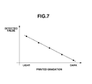
- FIG. 7 is a graph illustrating a result of detection of density gradation detection patches.
- FIG. 8 is a graph illustrating a result of white surface calibration made to the result of the detection of the density gradation detection patches.
- FIG. 9 is a conceptual diagram illustrating storage of information in a read-only memory (ROM) of the recording apparatus and a colorimetric sensor according to the exemplary embodiment of the present invention.
- ROM read-only memory
- FIG. 10 is a graph illustrating an influence of a variation in spectral sensitivity.
- FIG. 11 is a graph illustrating an influence of a variation in spectral sensitivity.
- FIG. 12 is a graph illustrating a difference in discharge amount for each of different recording apparatuses.
- FIG. 13 is a graph illustrating an emission wavelength spectrum for each supplied current.
- FIG. 1 is a partially exploded perspective view illustrating an internal configuration of the inkjet recording apparatus 1 provided with the colorimetric device 2 according to the exemplary embodiment of the present invention.
- FIG. 6A is a schematic cross-sectional view illustrating the inkjet recording apparatus 1 .
- a sheet (roll paper) wound into a rolled state as a sheet of a recording medium is used in the inkjet recording apparatus 1 . While one end of the wound roll paper is conveyed, ink is discharged from a recording head 50 , which is an ink discharge head, onto the sheet 3 , thereby recording an image.
- the inkjet recording apparatus 1 includes a platen 20 , which supports the sheet 3 in a planar state.
- a conveyance roller 4 and a pinch roller 21 are disposed within the inkjet recording apparatus 1 as a conveyance mechanism that conveys the sheet 3 .
- a conveyance motor 24 is connected to the conveyance roller 4 via a conveyance belt 22 and a conveyance pulley 23 .
- the conveyance pulley 23 is fixed to a shaft of the conveyance roller 24 .
- a driving force by the conveyance motor 24 is transmitted to the conveyance pulley 23 via the conveyance belt 22 .
- the rotational driving force transmitted to the conveyance pulley 23 is transmitted to the conveyance roller 4 , whereby the conveyance roller 4 is rotationally driven.
- the leading edge of the roll paper 3 is wound off from a roll paper feeding unit 25 by the rotational driving of the conveyance roller 4 with the leading edge of the roll paper 3 sandwiched and nipped between the conveyance roller 4 and the pinch roller 21 .
- an image forming unit 26 includes the recording head 50 , a recording carriage 5 , and the platen 20 .
- the recording carriage 5 with the recording head 50 mounted thereon is disposed at an opposite position from the platen 20 in the inkjet recording apparatus 1 .
- the recording carriage 5 is configured to perform a reciprocal scanning operation along guide members 6 and 7 in a direction perpendicular to a direction in which the sheet 3 is conveyed.
- the inkjet recording apparatus 1 includes the recording head 50 capable of discharging ink.
- the recording head 50 can vertically move the recording head 50 relative to the platen 20 according to the type of a sheet and an environment in which the inkjet recording apparatus 1 is used.
- the recording head 50 records the image on the sheet 3 by discharging the ink at a predetermined position of the sheet 3 based on image information.
- a discharge port array is formed by a plurality of discharge ports arrayed at predetermined pitches on a discharge surface of the recording head 50 opposite the sheet 3 . In a case where inks of a plurality of colors are used for, for example, color recording, a plurality of discharge port arrays corresponding to the respective ink colors is formed.
- a heating element (an electrothermal converter) is provided in a flow path in the recording head 50 to correspond to each of the discharge ports.
- the heating element is energized via a wiring to generate heat energy, so that the ink in the flow path is heated to bubble due to film boiling.
- An ink droplet is discharged from the discharge port due to bubbling energy at this time.
- a recording operation in which the ink is discharged toward a recording region of the sheet 3 on the platen 20 while the recording head 50 moves in a main scanning direction, and a conveyance operation, in which the sheet 3 is conveyed in a sub-scanning direction by a distance corresponding to a recording width of the sheet 3 , are repeated. Images are sequentially recorded on the sheet 3 by a repetition of these operations.
- the recording head 50 operates based on the method for discharging an ink droplet by causing film boiling to bubble the ink using the heating element, but the exemplary embodiment of the present invention is not limited thereto.
- a recording head based on a method for discharging liquid in the recording head by deforming a piezoelectric element may be employed to the recording apparatus.
- another type of recording head may be employed to the recording apparatus according to the exemplary embodiment of the present invention.
- the colorimetric device 2 includes a colorimetric sensor 10 . Further, the colorimetric device 2 includes a colorimetric carriage 13 . A colorimetric sensor holder 14 is mounted on the colorimetric carriage 13 , and the colorimetric sensor 10 is attached to the colorimetric sensor holder 14 . The colorimetric sensor 10 can perform colorimetry on the recorded image recorded on the sheet 3 .
- the colorimetric sensor 10 is disposed at a downstream side relative to the recording head 50 in the direction in which the sheet 3 is conveyed.
- the colorimetric sensor 10 is mounted on the colorimetric carriage 13 , which is configured to perform a scanning operation in the main scanning direction intersecting with (in the present exemplary embodiment, in the direction approximately perpendicular to) the direction in which the sheet 3 is conveyed.
- the colorimetric sensor 10 moves in the main scanning direction according to a movement of the colorimetric carriage 13 in the main scanning direction. In this manner, the colorimetric sensor 10 can perform the colorimetry on a test pattern recorded on the sheet 3 while scanning the test pattern in the main scanning direction.
- the colorimetric device 2 includes the colorimetric carriage 13 , as a scanning unit, for moving the colorimetric sensor 10 relative to the sheet 3 to scan the image, and a scanning mechanism of the colorimetric carriage 13 .
- the inkjet recording apparatus 1 includes a support member 19 for supporting the sheet 3 at a position corresponding to the colorimetric device 2 .
- the colorimetric device 2 can perform the colorimetry on the recorded image recorded on the sheet 3 with the sheet 3 supported on the support member 19 .
- the colorimetric sensor 10 includes a light emitting element used as a light source such as a light-emitting diode (LED). Further, the colorimetric sensor 10 includes a light receiving element capable of receiving light such as a photodiode. During execution of colorimetry, light is emitted from the light emitting element toward the sheet 3 . The emitted light is reflected on the recoded image of the sheet 3 , and the reflected light therefrom is received by the light receiving element. Then, color information, such as an optical density, of the recorded image can be measured based on a light amount received by the light receiving element.
- a light emitting element used as a light source such as a light-emitting diode (LED).
- the colorimetric sensor 10 includes a light receiving element capable of receiving light such as a photodiode.
- light is emitted from the light emitting element toward the sheet 3 .
- the emitted light is reflected on the recoded image of the sheet 3
- the colorimetric carriage 13 is pivotally supported by a guide rail 15 . Further, the colorimetric carriage 13 is configured to perform a reciprocal scanning operation in a direction in which the guide rail 15 extends by not-illustrated driving source and driving belt. As a result, it is possible to maintain a constant relative distance and a constant relative angle between the colorimetric sensor 10 and the sheet 3 . Therefore, it is possible for the colorimetric sensor 10 to accurately perform the colorimetry.
- the colorimetric device 2 includes a pressing member 17 .
- the pressing member 17 is disposed in such a manner to be able to contact the sheet 3 to press a recording surface of the sheet 3 from above during the execution of colorimetry. Since the sheet 3 is pressed against a support surface during the execution of colorimetry, the constant distance between the colorimetric sensor 10 and the sheet 3 can be maintained even if a winding or a curl is generated on the sheet 3 . Thus, the colorimetry can be accurately performed. Further, during the execution of colorimetry, the colorimetric sensor 10 is guided in the scanning direction by the guide rail 15 . Further, four wheels (contacting members) 16 are attached to a bottom of the colorimetric sensor holder 14 .
- the wheels 16 attached to the colorimetric sensor 10 contact a top of the pressing member 17 .
- the wheels 16 rotate and roll on the pressing member 17 while contacting the pressing member 17 , so that the colorimetric carriage 13 moves.
- the colorimetric sensor holder 14 includes a rotational shaft 14 a that extends in parallel with the scanning direction, in which the colorimetric sensor 10 scans an image.
- U-shaped elongated holes 13 a are formed on both side surfaces of the colorimetric carriage 13 .
- the colorimetric sensor holder 14 is disposed to extend perpendicularly to the scanning direction of the colorimetric carriage 13 .
- the colorimetric sensor holder 14 and the colorimetric carriage 13 are engaged with each other with the rotational shaft 14 a disposed within the elongated holes 13 a.
- the rotational shaft 14 a is disposed to be vertically movable along the elongated holes 13 a.
- the colorimetric sensor holder 14 is disposed to be movable toward or away from the sheet 3 relative to the colorimetric carriage 13 .
- a pressing spring 18 is disposed at the colorimetric carriage 13 , and presses the colorimetric sensor holder 14 against the pressing member 17 via the wheels 16 . While the colorimetric sensor holder 14 is urged downward by the colorimetric carriage 13 via the pressing spring 18 , the wheels 16 contact the pressing member 17 . Therefore, the colorimetric sensor 10 is urged toward the sheet 3 , and the colorimetric sensor holder 14 can perform scanning according to a shape of a surface of the pressing member 17 .
- the colorimetric sensor holder 14 is urged downward by the pressing spring 18 , so the wheels 16 can press the sheet 3 against the support member 19 via the pressing member 17 during the execution of colorimetry.
- the wheels 16 are urged toward the sheet 3 and roll while contacting the pressing member 17 , so that the colorimetric sensor 10 moves relative to the sheet 3 to scan the image. Therefore, it is possible for the colorimetric device 2 to hold the sheet 3 from above, and to prevent the sheet 3 from floating from the support member 19 during the execution of colorimetry.
- the wheels 16 does not contact the pressing member 17 , the sheet 3 is pressed only by the weight of the pressing member 17 .
- the colorimetric device 2 includes a colorimetric device frame 11 that stores the colorimetric sensor holder 14 and the pressing member 17 .
- the colorimetric device frame 11 is attached to a housing 31 on a main body side of the inkjet recording apparatus 1 via a spring.
- an elevating cam 12 is rotatably attached to the housing 31 on the main body side of the inkjet recording apparatus 1 .
- a rotation of the elevating cam 12 can cause the colorimetric device 2 to move toward or away from the housing 31 .
- FIG. 6B is a cross-sectional view illustrating the inkjet recording apparatus 1 when the rotation of the elevating cam 12 causes the colorimetric device 2 to move away from the housing 31 , and thus the colorimetric device 2 moves toward the sheet 3 .
- the colorimetric sensor 10 When the colorimetry is performed on the recorded image recorded on the sheet 3 by the colorimetric sensor 10 , the colorimetric sensor 10 is moved to be positioned close to sheet 3 by the rotation of the elevating cam 12 , and in this state, the colorimetry can be performed.
- FIG. 2 is a schematic cross-sectional view illustrating the colorimetric sensor 10 .
- the colorimetric sensor 10 includes a light emitting portion 11 and a light receiving portion 12 .
- a light beam 160 emitted from the light emitting portion 11 is reflected on the surface of the sheet 3 , which is a recording medium.
- the light receiving portion 12 is disposed to be able to receive light with a reflection angle different from an angle at which the light is incident from the light emitting portion 11 .
- a detected and acquired detection signal is transmitted to an electric substrate of the printer.
- a white LED or a three-color LED is used as the light emitting portion 11
- a photoelectric conversion element sensitive to a visual light range is used as the light receiving portion 12 , to adjust registration for the recording head 50 that discharges all types of inks including main color inks, such as Cyan (C), Magenta (M), Yellow (Y), and Black (K), and special color inks.
- main color inks such as Cyan (C), Magenta (M), Yellow (Y), and Black (K)
- main color inks such as Cyan (C), Magenta (M), Yellow (Y), and Black (K)
- special color inks such as Cyan (C), Magenta (M), Yellow (Y), and Black (K)
- main color inks such as Cyan (C), Magenta (M), Yellow (Y), and Black (K)
- special color inks such as Cyan (C), Magenta (M), Yellow (Y), and Black (K)
- special color inks such as Cyan
- the present exemplary embodiment may be realized as long as the detection resolution is high enough to detect a relative density difference among the respective patterns (a single pattern included in an adjustment pattern group will be hereinafter referred to as a “patch”) belonging to the adjustment pattern group, which will be described below.
- the present exemplary embodiment may be realized as long as detection of the colorimetric sensor 10 is stable enough not to affect the detected density difference before the colorimetric sensor 10 completes detecting all of the patches in the adjustment pattern group.
- the sensitivity is adjusted, for example, after the colorimetric device 2 is moved to a non-recording region of the sheet 3 .
- the adjustment method the light emitting strength of the light emitting portion 11 is adjusted in such a manner that the detection level reaches an upper limit value.
- another possible method is to adjust a gain of a detection amplifier in the light receiving portion 12 .
- the sensitivity does not necessarily have to be adjusted, but the sensitivity adjustment is effective as a method for improving a signal-to-noise (S/N) ratio to increase the detection accuracy.
- S/N signal-to-noise
- the spatial resolution of the colorimetric sensor 10 is a resolution allowing detection of a region smaller than a region where a single adjustment pattern is printed.
- a printing width in the sub-scanning direction reduces according to the number of passes, so the resolution of the colorimetric sensor 10 is limited by the number of printing passes. Further, the number of printing passes (the printing width) for printing the adjustment pattern may be determined from the resolution of the colorimetric sensor 10 .
- FIG. 3 is a schematic block diagram illustrating a control circuit of a color inkjet printer according to the first exemplary embodiment.
- a controller 400 is a main control unit, and includes a central processing unit (CPU) 401 in the form of, for example, a microcomputer, a read-only memory (ROM) 403 storing a program, a required table, and other fixed data, and a random access memory (RAM) 405 including, for example, an area where image data is developed and a working area.
- a host apparatus 410 is a supply source of image data. More specifically, the host apparatus 401 may be embodied in the form of not only a computer that, for example, generates and processes data such as an image regarding printing, but also a reader unit for image reading, and the like. The image data, another command, a status signal, and others are transmitted to and received from the controller 400 via an interface (I/F) 412 .
- I/F interface
- An operation unit 420 is a switch group that receives an instruction input by an operator.
- the operation unit 420 includes a power source switch 422 , and a recovery switch 426 for instructing activation of suction recovery. Further, the operation unit 420 includes a registration adjustment activation switch 427 for manually adjusting registration, a registration adjustment value setting input unit 429 for manually inputting an adjustment value of the registration, and others.
- a sensor group 430 is a sensor group for detecting the status of the apparatus, and includes the above-described reflective colorimetric sensor 10 , a photocoupler 109 for detecting a home position, a temperature sensor 434 disposed at an appropriate position to detect an ambient temperature, and others.
- a head driver 440 is a driver configured to drive a discharge heater in the recording head 50 according to, for example, print data.
- the head driver 440 includes a shift register for aligning the print data in such a manner to correspond to the position of the discharge heater, and a latch circuit for latching information at appropriate timing. Further, the head driver 440 includes a timing setting unit for appropriately setting driving timing (discharge timing) for aligning dot forming positions, and others, in addition to a logic circuit element for actuating the discharge heater in synchronization with a driving timing signal.
- a sub heater is included in the recording head 50 .
- the sub heater adjusts a temperature to stabilize the discharge characteristic of ink, and may be formed on a print head substrate together with the discharge heater and/or may be attached to a print head main body or a head cartridge.
- a motor driver 450 is a driver for driving a main scanning (carriage) motor 452 .
- a sub-scanning (linefeed (LF)) motor 462 is a motor used to convey (sub-scan) a print medium.
- a motor driver 460 is a driver for the sub-scanning motor 462 .
- FIG. 4 is a typical flowchart illustrating the present exemplary embodiment of the present invention.
- the inkjet recording apparatus 1 prints patches for detecting densities of each color on a recording medium.
- the inkjet recording apparatus 1 prints gradation patches for each ink color based on predetermined input values.
- the input values may be different for each ink color. For example, for a light color, high input values are set to increase the detection sensitivity. Further, the input values of the gradation patches do not necessarily have to be uniform gradations. Especially, ink of a dark color results in saturation of a printing result in a region to which a high input value is set, so it is effective to increase the number of patches with a low gradation.
- FIG. 5A illustrates an example of a density gradation detection patch group.
- a patch 200 corresponds to a high input value
- a patch 210 corresponds to a low input value.
- a high input value leads to an increase in the number of discharged droplets, resulting in a high printing duty.
- the density gradation detection patches may be disposed at any position of the recording medium. It is desirable to arrange patterns with a blank space left between the patterns to prevent the sheet from being wet to undulate, to stabilize the detection result.
- FIG. 5B is a schematic view illustrating a layout of a density gradation detection patch group.
- a print patch group 220 is arranged in an X direction of the scanning direction of the colorimetric carriage 13 and the recording carriage 5 .
- a print patch group 230 includes the conveyance direction.
- Cockling is such a phenomenon that a large amount of liquid droplets swells a recording medium to displace the recording medium from the platen 20 , resulting in generation of undulation. Therefore, it is effective to arrange the patterns in such a manner to reduce an amount of liquid droplets in a predetermined area.
- dark patches and light patches are alternately disposed in the carriage scanning direction.
- the patches themselves are arranged in a staggered manner, and dark patches and light patches are vertically alternately disposed. That reduces an amount of liquid droplets in the predetermined area.
- step S 4 - 2 the inkjet recording apparatus 1 detects an output on the recording medium.
- the result of the detection on the recording medium is used as a reference of a white level. It is desirable to detect the output on the recording medium in a same condition as printed gradation patches to reduce a detection variation of the colorimetric sensor 10 . For example, a difference in positions in the carriage direction changes a distance between the colorimetric sensor 10 and the sheet, affecting the detection result. Therefore, it is desirable to detect the output on the recording medium at the same position as the carriage position direction. Further, as described above, it is desirable to calibrate the output of the colorimetric sensor 10 according to the white level.
- the colorimetric sensor 10 is set in such a manner that a width of an analog to digital (AD) detection range of hardware is maximized based on the white level to increase a dynamic range of detection.
- AD analog to digital
- step S 4 - 3 the inkjet recording apparatus 1 detects outputs on the patches.
- the inkjet recording apparatus 1 detects the gradation patches printed on the recording medium using the setting of the colorimetric sensor 10 , which is used in detection on the medium.
- FIG. 7 schematically illustrates a result of the detection of the density gradation detection patches.
- FIG. 7 is a graph in which detected values corresponding to the printed gradation values are plotted.
- a patch of a small input value corresponds to a large detected value
- a patch of a large input value corresponds to a small detected value
- FIG. 8 schematically illustrates a result of white surface calibration performed on the result of the detection of the density gradation detection patches.
- the result of the detection of the density gradation detection patches is calibrated using the output on the recording medium, thereby performing white surface calibration. Use of the result can reduce an influence of a variation in the white level of the recording medium.
- step S 4 - 4 the inkjet recording apparatus 1 corrects the detection result.
- the inkjet recording apparatus 1 corrects the result of the detection of the density gradation detection patches after the white surface calibration.
- the spectral sensitivity characteristics of the light emitting portion and the light receiving portion 12 mounted on the colorimetric sensor 10 vary for each colorimetric sensor. Further, a patch printed on a recording medium also has a spectral reflection characteristic.
- FIG. 10 schematically illustrates spectral sensitivities out of alignment.
- a vertical axis A in FIG. 10 indicates a relative sensitivity, and has no unit of quantity.
- a line 290 indicates an element spectral sensitivity characteristic A (a spectral sensitivity characteristic of a first colorimetric sensor).
- a line 300 indicates an element spectral sensitivity characteristic B (a spectral sensitivity characteristic of a colorimetric sensor different from the first colorimetric sensor).
- a line 310 indicates a spectral reflection characteristic of ink printed on the recording medium.
- the spectral sensitivity characteristic varies depending on an employed colorimetric sensor. Therefore, when a same gradation patch is detected using colorimetric sensors having difference spectral sensitivities, the detection results are different. To solve this problem, the present exemplary embodiment corrects a variation in the detected values due to the spectral sensitivity characteristic of the colorimetric sensor 10 .
- a reference spectral sensitivity characteristic is stored in, for example, the ROM 403 in the main body of the inkjet recording apparatus 1 in advance, and a spectral sensitivity characteristic of the colorimetric sensor 10 is stored in the colorimetric sensor 10 or in the ROM 403 in the main body of the inkjet recording apparatus 1 in advance.
- the inkjet recording apparatus 1 acquires the reference spectral sensitivity characteristic and the spectral sensitivity characteristic of the colorimetric sensor 10 by reading them.
- FIG. 9 is a conceptual diagram illustrating information stored in the ROM 403 of the inkjet recording apparatus 1 and the colorimetric sensor 10 .
- the reference spectral sensitivity characteristic means a spectral sensitivity characteristic of a typical colorimetric sensor for performing calibration. It is desirable to set the reference spectral sensitivity characteristic to the median of a variation among elements, but the reference spectral sensitivity characteristic does not necessarily have to be the median.
- FIG. 11 schematically illustrates a result of detection performed on gradation patches by a colorimetric sensor having the reference spectral sensitivity characteristic, and a result of detection performed on the same gradation patches by a colorimetric sensor having a different spectral sensitivity characteristic from the reference spectral sensitivity characteristic.
- a line 240 indicates the result detected by the colorimetric sensor having the reference spectral sensitivity characteristic.
- a line 250 indicates the result detected by the colorimetric sensor having the different spectral sensitivity characteristic from the reference spectral sensitivity characteristic. Assume that A indicates an ink spectral sensitivity characteristic of a gradation patch, B indicates the reference spectral sensitivity characteristic of the light emitting portion, C indicates the reference spectral sensitivity characteristic of the light receiving portion, D indicates the spectral sensitivity characteristic of the light emitting portion of a colorimetric sensor, and E indicates the spectral sensitivity characteristic of the light receiving portion of the colorimetric sensor.
- the integration range may be the visible light.
- the inkjet recording apparatus 1 refers to, by a reference unit in the CPU 401 , the reference information stored in the apparatus main body and the individual information stored in the colorimetric sensor 10 , and corrects the detection result using the reference information and the individual information, thereby correcting a variation in the detection result due to the individual difference.
- the light emitting characteristic and the light receiving characteristic as the spectral sensitivity characteristics stored in the colorimetric sensor 10 mounted on the inkjet recording apparatus 1 includes values indicating the light emitting characteristic and the light receiving characteristic of the colorimetric sensor 10 .
- the spectral sensitivity characteristics may include information indicating a difference from the reference spectral sensitivity characteristic. In this case, the detection result may be corrected based on the referred difference information.
- step S 4 - 5 the inkjet recording apparatus 1 corrects an ink discharge amount.
- the inkjet recording apparatus 1 corrects the ink discharge amount from the corrected result of the detection of the printed gradation patches.
- FIG. 12 schematically illustrates a change in the discharge amount for each recording apparatus.
- a line 260 indicates a relationship between an input value and a discharge amount with respect to a reference recording apparatus that discharges a standard amount, which is determined as a reference in advance.
- a line 270 indicates a relationship between an input value and a discharge amount with respect to a recording apparatus, which discharges an amount larger than the discharge amount of the reference recording apparatus when discharging ink based on this signal.
- a line 280 indicates a relationship between an input value and a discharge amount with respect to a recording apparatus, which discharges an amount smaller than the discharge amount of the reference recording apparatus when discharging ink based on the signal.
- the inkjet recording apparatus 1 corrects the discharge amount based on the detection result obtained by the correction in the spectral sensitivity characteristic of the colorimetric sensor 10 in step S 4 - 4 . In a case where the inkjet recording apparatus 1 detects that the detected printed density is lower than the printed density of the reference recording apparatus, the inkjet recording apparatus 1 corrects an input signal value in such a manner to increase the discharge amount relative to the input value.
- the inkjet recording apparatus 1 corrects the input signal value in such a manner to reduce the discharge amount.
- Information defining a change of the signal value for the correction may be stored in the ROM 403 , and the inkjet recording apparatus 1 may read the information and cause the CPU 401 to perform control in such a manner to change the discharge amount.
- the inkjet recording apparatus 1 can output a pixel value of input image data which is changed based on the correction in step S 4 - 5 in such a manner that the value is transmitted to the recording head 50 .
- the input image data may include ink data indicating a gradation value for each of the colors of inks to be used in printing, Red/Green/Blue (RGB) data indicating a gradation value by an RGB value, and dot data that determines whether a dot is recorded.
- ink data indicating a gradation value for each of the colors of inks to be used in printing
- RGB data indicating a gradation value by an RGB value
- dot data that determines whether a dot is recorded.
- the inkjet recording apparatus 1 corrects a variation in the spectral sensitivity of the colorimetric sensor 10 without using a calibration chart when detecting the densities of printed patches.
- FIG. 13 is a conceptual diagram illustrating an emission wavelength spectrum for each supplied current.
- a line 32 indicates a peak wavelength where an output approximately reaches a peak at spectra k and j corresponding to low currents.
- a line 33 indicates a peak wavelength where an output approximately reaches a peak at spectra h and g corresponding to high currents.
- FIG. 13 illustrates how the peak wavelength shifts according to a current amount. It is desirable that the wavelength characteristic of the light emitting element is stored in the colorimetric sensor 10 for each current.
- a plurality of supplied currents and a plurality of emission spectra are stored in advance. Further, the emission spectrum may be interpolated between the stored currents. For example, an emission spectrum corresponding to a supplied current of 5 mA and an emission spectrum corresponding to a supplied current of 10 mA are stored in the colorimetric sensor 10 .
- the supplied current is 7.5 mA at the time of detection of a gradation patch
- a spectrum corresponding to 7.5 mA is calculated from the emission spectra of 5 mA and 10 mA.
- a desired spectrum may be acquired by performing linear interpolation on the currents.
- the elements within the colorimetric sensor 10 are identified by the colorimetric sensor 10 itself. According to the present exemplary embodiment, it is unlikely that the light emitting element and the light receiving element are changed independently. Therefore, the spectral sensitivity characteristics of the light emitting element and the light receiving element may be stored as one data. The same applies to the spectral sensitivity characteristics of the reference light emitting element and the reference light receiving element, which are stored in the main body of the inkjet recording apparatus 1 .
- an optical spectral intensity relatively increases around a peak wavelength (for example, refer to the lines 290 and 300 in FIG. 10 ). Therefore, information may be stored in the region around the peak wavelength at a short interval, and information may be stored in other wavelength regions at a long interval. More specifically, in a wavelength band where a value of a spectral sensitivity of a measurement unit according to a wavelength is higher than half the value of a peak, values of the spectral sensitivity in a predetermined wavelength range (for example, a range of 30 nm) are stored at 2-nm intervals.
- a predetermined wavelength range for example, a range of 30 nm
- values of the spectral sensitivity in the same range are stored at 5-nm intervals.
- the emission wavelength of the monochromatic LED is different for each light emission color (for example, R, G, and B), so the wavelength region, in which information is stored at a short interval, varies for each color.
- the spectral sensitivity characteristic of the light emitting portion 11 is stored according to the above-described method.
- the ink spectral sensitivity characteristic of the gradation patch may be acquired by measuring and storing the ink spectral sensitivity characteristic in the main body of the inkjet recording apparatus 1 in advance.
- this method cannot be used for a recording medium unprepared in advance. Therefore, in this case, a gradation patch printed on the recording medium is measured by a separate measurement device, and is stored in the main body of the inkjet recording apparatus 1 .
- the ink spectral sensitivity characteristic of the gradation patch may be acquired by using the method.
- the ink spectral sensitivity characteristic of the gradation patch may be acquired by using a colorimetric device capable of acquiring spectral data of visible light.
- the ink spectral sensitivity characteristic is acquired for each gradation patch printed on a recording medium according to the above-described method.
- aspects of the present invention can also be realized by a computer of a system or apparatus (or devices such as a CPU or MPU) that reads out and executes a program recorded on a memory device to perform the functions of the above-described embodiment(s), and by a method, the steps of which are performed by a computer of a system or apparatus by, for example, reading out and executing a program recorded on a memory device to perform the functions of the above-described embodiment(s).
- the program is provided to the computer for example via a network or from a recording medium of various types serving as the memory device (e.g., computer-readable medium).
- the program may be executed by a single computer, or a plurality of computers in cooperation with one another.
Landscapes
- Engineering & Computer Science (AREA)
- Multimedia (AREA)
- Signal Processing (AREA)
- Ink Jet (AREA)
Abstract
Description
U1=∫A×B×C (1)
U2=∫A×D×E (2)
DETECTION RESULT (AFTER CORRECTION)=D2×U1/U2 (3)
Claims (19)
Applications Claiming Priority (2)
| Application Number | Priority Date | Filing Date | Title |
|---|---|---|---|
| JP2012-102479 | 2012-04-27 | ||
| JP2012102479 | 2012-04-27 |
Publications (2)
| Publication Number | Publication Date |
|---|---|
| US20130286080A1 US20130286080A1 (en) | 2013-10-31 |
| US9186922B2 true US9186922B2 (en) | 2015-11-17 |
Family
ID=49476863
Family Applications (1)
| Application Number | Title | Priority Date | Filing Date |
|---|---|---|---|
| US13/863,915 Active US9186922B2 (en) | 2012-04-27 | 2013-04-16 | Recording apparatus and image processing method |
Country Status (2)
| Country | Link |
|---|---|
| US (1) | US9186922B2 (en) |
| JP (1) | JP6261184B2 (en) |
Families Citing this family (3)
| Publication number | Priority date | Publication date | Assignee | Title |
|---|---|---|---|---|
| JP6506601B2 (en) * | 2015-04-21 | 2019-04-24 | キヤノン株式会社 | Recording device, judgment method |
| JP6598568B2 (en) * | 2015-08-10 | 2019-10-30 | キヤノン株式会社 | Image forming apparatus |
| JP6930257B2 (en) * | 2016-07-26 | 2021-09-01 | 株式会社リコー | Items to be transported and liquid discharge device |
Citations (5)
| Publication number | Priority date | Publication date | Assignee | Title |
|---|---|---|---|---|
| JPH09171279A (en) | 1995-12-20 | 1997-06-30 | Fuji Xerox Co Ltd | Color image output device |
| US6876467B1 (en) * | 1999-08-19 | 2005-04-05 | Fuji Photo Film Co., Ltd. | Printer with automatic density adjusting function and density adjusting method of printer |
| US20080007587A1 (en) * | 2006-07-07 | 2008-01-10 | Masaru Watanabe | Image forming apparatus |
| US20090238976A1 (en) * | 2008-03-19 | 2009-09-24 | Canon Kabushiki Kaisha | Ink jet ink, ink jet recording method, ink cartridge, recording unit, and ink jet recording apparatus |
| US20110141183A1 (en) * | 2009-12-11 | 2011-06-16 | Canon Kabushiki Kaisha | Inkjet recording apparatus and landing-location adjustment method |
Family Cites Families (3)
| Publication number | Priority date | Publication date | Assignee | Title |
|---|---|---|---|---|
| JP5153196B2 (en) * | 2007-04-18 | 2013-02-27 | キヤノン株式会社 | DATA GENERATION DEVICE, RECORDING DEVICE, CALIBRATION DEVICE, AND DATA GENERATION METHOD |
| JP2009143188A (en) * | 2007-12-17 | 2009-07-02 | Canon Inc | Image forming apparatus and calibration method |
| JP2010120219A (en) * | 2008-11-18 | 2010-06-03 | Canon Inc | Printer and method for calibrating printer |
-
2013
- 2013-04-16 US US13/863,915 patent/US9186922B2/en active Active
- 2013-04-26 JP JP2013094324A patent/JP6261184B2/en active Active
Patent Citations (5)
| Publication number | Priority date | Publication date | Assignee | Title |
|---|---|---|---|---|
| JPH09171279A (en) | 1995-12-20 | 1997-06-30 | Fuji Xerox Co Ltd | Color image output device |
| US6876467B1 (en) * | 1999-08-19 | 2005-04-05 | Fuji Photo Film Co., Ltd. | Printer with automatic density adjusting function and density adjusting method of printer |
| US20080007587A1 (en) * | 2006-07-07 | 2008-01-10 | Masaru Watanabe | Image forming apparatus |
| US20090238976A1 (en) * | 2008-03-19 | 2009-09-24 | Canon Kabushiki Kaisha | Ink jet ink, ink jet recording method, ink cartridge, recording unit, and ink jet recording apparatus |
| US20110141183A1 (en) * | 2009-12-11 | 2011-06-16 | Canon Kabushiki Kaisha | Inkjet recording apparatus and landing-location adjustment method |
Also Published As
| Publication number | Publication date |
|---|---|
| JP6261184B2 (en) | 2018-01-17 |
| JP2013241004A (en) | 2013-12-05 |
| US20130286080A1 (en) | 2013-10-31 |
Similar Documents
| Publication | Publication Date | Title |
|---|---|---|
| US7798634B2 (en) | Recording apparatus and control method | |
| US10207495B2 (en) | Image forming apparatus, method for calculating actual distance of deviation, and computer program product storing same | |
| US9809035B2 (en) | Methods, systems, and devices for inkjet color management | |
| US10583650B2 (en) | Adjusting a drive signal to compensate for a difference between pattern portions | |
| US9998633B2 (en) | Color irregularity detecting device, image forming apparatus, and color irregularity detecting method | |
| JP2015078975A (en) | Glossiness determination device, color measuring device, image forming apparatus, and glossiness determination method | |
| US8960845B2 (en) | Color analysis | |
| US8974032B2 (en) | Image processing method, image processing device, recording medium and image formation device | |
| US10735621B2 (en) | Printing apparatus and determination method | |
| JP2013226759A (en) | Recording apparatus, control apparatus and control method | |
| US7537304B2 (en) | Apparatus and methods for color sensor calibration in a multi-die printer | |
| CN110949003B (en) | Liquid ejecting apparatus, liquid ejecting method, and storage medium | |
| US9186922B2 (en) | Recording apparatus and image processing method | |
| JP6598711B2 (en) | Inkjet recording apparatus and pattern recording method for correcting applied amount | |
| JP2005271372A (en) | Image forming device and method of correcting image forming position | |
| JP7354698B2 (en) | Liquid discharge device, liquid discharge method, and program | |
| US20100238221A1 (en) | Recording apparatus and recording position adjustment method | |
| JP2010120219A (en) | Printer and method for calibrating printer | |
| JP7585925B2 (en) | PRINTING DEVICE AND METHOD FOR GENERATING COLOR CHART DATA | |
| JP2005271369A (en) | Image forming device and method of correcting image forming position | |
| US20110187779A1 (en) | Inkjet recording apparatus and recording position adjustment method | |
| JP2013141799A (en) | Program preparation method, density correcting method, and printing method | |
| JP2021112823A (en) | Ink jet printer and method of confirming intensity of light | |
| US20250083452A1 (en) | Printing apparatus, method for controlling printing apparatus, and storage medium | |
| US11135861B2 (en) | Method for manufacturing printing apparatus, and printing apparatus |
Legal Events
| Date | Code | Title | Description |
|---|---|---|---|
| AS | Assignment |
Owner name: CANON KABUSHIKI KAISHA, JAPAN Free format text: ASSIGNMENT OF ASSIGNORS INTEREST;ASSIGNOR:UCHIDA, NAOKI;REEL/FRAME:030881/0131 Effective date: 20130410 |
|
| STCF | Information on status: patent grant |
Free format text: PATENTED CASE |
|
| MAFP | Maintenance fee payment |
Free format text: PAYMENT OF MAINTENANCE FEE, 4TH YEAR, LARGE ENTITY (ORIGINAL EVENT CODE: M1551); ENTITY STATUS OF PATENT OWNER: LARGE ENTITY Year of fee payment: 4 |
|
| MAFP | Maintenance fee payment |
Free format text: PAYMENT OF MAINTENANCE FEE, 8TH YEAR, LARGE ENTITY (ORIGINAL EVENT CODE: M1552); ENTITY STATUS OF PATENT OWNER: LARGE ENTITY Year of fee payment: 8 |