US91849A - Pneumatic dental plugger - Google Patents
Pneumatic dental plugger Download PDFInfo
- Publication number
- US91849A US91849A US91849DA US91849A US 91849 A US91849 A US 91849A US 91849D A US91849D A US 91849DA US 91849 A US91849 A US 91849A
- Authority
- US
- United States
- Prior art keywords
- tool
- cylinder
- piston
- hammer
- cap
- Prior art date
- Legal status (The legal status is an assumption and is not a legal conclusion. Google has not performed a legal analysis and makes no representation as to the accuracy of the status listed.)
- Expired - Lifetime
Links
- HHNFORCFJOVQNF-UHFFFAOYSA-N cyl-1 Chemical compound N1C(=O)C(CCCCCC(=O)C2OC2)NC(=O)C2CCCN2C(=O)C(C(C)CC)NC(=O)C1CC1=CC=C(OC)C=C1 HHNFORCFJOVQNF-UHFFFAOYSA-N 0.000 description 2
- 239000002184 metal Substances 0.000 description 2
- 101100441844 Caenorhabditis elegans cyl-1 gene Proteins 0.000 description 1
- 101100382953 Mus musculus Ccnd1 gene Proteins 0.000 description 1
- 238000009833 condensation Methods 0.000 description 1
- 230000005494 condensation Effects 0.000 description 1
- 238000010276 construction Methods 0.000 description 1
- 235000011389 fruit/vegetable juice Nutrition 0.000 description 1
- 101150115956 slc25a26 gene Proteins 0.000 description 1
Images
Classifications
-
- A—HUMAN NECESSITIES
- A61—MEDICAL OR VETERINARY SCIENCE; HYGIENE
- A61C—DENTISTRY; APPARATUS OR METHODS FOR ORAL OR DENTAL HYGIENE
- A61C11/00—Dental articulators, i.e. for simulating movement of the temporo-mandibular joints; Articulation forms or mouldings
- A61C11/02—Dental articulators, i.e. for simulating movement of the temporo-mandibular joints; Articulation forms or mouldings characterised by the arrangement, location or type of the hinge means ; Articulators with pivots
Definitions
- Lam Patent Na. 91,849, am Juice 29, 1869 ⁇ maovemmr m "them-me DENTAL PLUG-G333.
- Figure 3 is a. sectional view of the same, showing "the'coustituent parts, separated one from the other.
- Figure 4 is a top view of the cap D.
- Figure 5 is a side view of the socket for the shank of the plugging toph
- Figure 6 is a (1': viewer the said socket.
- Figure 1 is a top view of the elastic cushion, which is set in the cap D.
- A is the cylinder forming the tool-handle.
- i O is the socket for the shank of the tool, over which the cap 1) sets, fastened by the screw E, which is set into the peripherical groove E.
- G isthe elastic cushion, against which the lug H on the shank rests, for the purpose of giving an elastic blow, and for throwing the tool back aftereach blow. 4
- I is the piston or hammer, which slides in the cylinder or hapdle A.
- K is a swivel-joint, at the bottom of the handle A, over which the flexible pipe sets, and which allows the handle to be turned freely.
- the axis of the swivel also limits the recoil otthe hammer 1.
- the air-holes LL permit the entrance and escape -01 air between the piston and base of the 'tool.
- N N are two standards, for supporting the drivingwheel 0 and ths'fly-wheel B.
- R is the condensing and rarefying-cylinder.
- S is the piston, nwiprocated by the crank-pin .in the fly-wheei P, the said crank-pin being set in an eccentric, which is bedded near the centre of the fly-wheel.
- T is an air-passage from the cylinder R to the flexible pipe U, whose top end sets over the swivel K;
- V is a channel in the cap D, to allow the entrance of the lug, H on the tool-shank.
- W isa recess in the socket O, inwhich thclug H rests, to prevent thetool fromturning.
- X is a groovcin the cap D, in which-is set the clastic cushion G.
- Y is a channel. in the elastic cushion G, correspondr ing with and always opposite the channel in'the'cap D, and for the same p se Z is a short tube, inserted in thebcttom of the cyl- 1 index A, and is the axis oi the swivel K.-
- any required metal may be condensed into the cafities of teeth by pressing the tool against the inserted metal.
- the plugging-tool provided with :1. lug for securing it in the socket, and to prevent its rotation, sub stautially as described.
Landscapes
- Health & Medical Sciences (AREA)
- Oral & Maxillofacial Surgery (AREA)
- Dentistry (AREA)
- Epidemiology (AREA)
- Life Sciences & Earth Sciences (AREA)
- Animal Behavior & Ethology (AREA)
- General Health & Medical Sciences (AREA)
- Public Health (AREA)
- Veterinary Medicine (AREA)
- Dental Tools And Instruments Or Auxiliary Dental Instruments (AREA)
Description
.No. 91,849. I V PATBNTEB UNE 29, 1869.
i E. A. HYDE.
' PNEUMATIG DENTAL APLUGGER.
ms ECKERY u'mosnmnms cm. msmeyswn. 0. C.
clam-i. sine EDWARD A.--I1YDE,OFANN AR O MICHIGAN.
Lam Patent Na. 91,849, am: Juice 29, 1869} maovemmr m "them-me DENTAL PLUG-G333.
The Schedule referred to in these Letters Patent and making parts! the some.
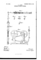
ratus for the purpose of filling teeth, which 1' call' the Pneumatic Dental Plngger; and I do hereby dc clare that the following is a full and exadt description of the construction and operation of the same, reference being bad to the accompanying drawings, and to the letters of reference mi rked thereon, making a part of this speeiiimtion, wherein-- Figure 1 is'a perspective view of thewhole appzv ratus, showing the connection of the pedal-cylinder, by means 'oi'a flexible pipe, wit-lithe handle.
- Figure2 is a sectional view of the handles with plugging-tool inserted;v s
Figure 3 is a. sectional view of the same, showing "the'coustituent parts, separated one from the other.
Figure 4 is a top view of the cap D. Figure 5 is a side view of the socket for the shank of the plugging toph Figure 6 is a (1': viewer the said socket. Figure 1 is a top view of the elastic cushion, which is set in the cap D.
A is the cylinder forming the tool-handle.
B is the plugging-tool. i O is the socket for the shank of the tool, over which the cap 1) sets, fastened by the screw E, which is set into the peripherical groove E.
G isthe elastic cushion, against which the lug H on the shank rests, for the purpose of giving an elastic blow, and for throwing the tool back aftereach blow. 4
- a I is the piston or hammer, which slides in the cylinder or hapdle A. J
K is a swivel-joint, at the bottom of the handle A, over which the flexible pipe sets, and which allows the handle to be turned freely. I The axis of the swivel also limits the recoil otthe hammer 1.
The air-holes LL permit the entrance and escape -01 air between the piston and base of the 'tool.
M is the base of the pedal-zuiparatus. N N are two standards, for supporting the drivingwheel 0 and ths'fly-wheel B. V
- Q is the pedal.
R is the condensing and rarefying-cylinder. S is the piston, nwiprocated by the crank-pin .in the fly-wheei P, the said crank-pin being set in an eccentric, which is bedded near the centre of the fly-wheel.
T is an air-passage from the cylinder R to the flexible pipe U, whose top end sets over the swivel K;
V is a channel in the cap D, to allow the entrance of the lug, H on the tool-shank.
W isa recess in the socket O, inwhich thclug H rests, to prevent thetool fromturning.
X is a groovcin the cap D, in which-is set the clastic cushion G.
Y is a channel. in the elastic cushion G, correspondr ing with and always opposite the channel in'the'cap D, and for the same p se Z is a short tube, inserted in thebcttom of the cyl- 1 index A, and is the axis oi the swivel K.-
The manner of operating the invention is as follows, to wit:
Tum thQ -ap D until the screw E pr'cvents its turn-r I log fu'rtherd ThechannelsV Y are now opposite the a recess W, allowing the plugging-point to be inserted, the lug H passing through the channels'V Yvinto recess \V. Now, by turning thecap D in the opposite direction, thechannels V Y are no longer opposite the lug H, and the pluggin tool is fastened. By working the pedal Q, the piston is made to reciprocate, whereby the'air contained in-the two cylinders and the connecting-pipe is alternately condensed and rarefied,
This condensation and rarefaction of the contained air cause the hammer I to reciprocate; the pressure of the-condensed air causing the forward stroke, and atmospheric pressure causing the. -recoil of the hammer.
The momentum of the =hammrhing'imparted to the.
plugging tool, any required metal" may be condensed into the cafities of teeth by pressing the tool against the inserted metal.
- As many as tour hundred blows per minuteare practicame'for the operator and easy for the vpatient;
By the use oi'ithis invention, from one hall' to, threef-Jurthsof the operatofls time is saved; the use of valves is entirely dispensed with, also use of springs; the 'size and weight of the, handle are reduced, and the liableness oi" getting out of order overcome.
\Vhat I claim, and desire to secure by Letters-:Pab' cut. is-
1. The tool-handle or cylinder carrying the piston or hammer, connected bynieans of a flexible pipe :with the condensing and rarefying-cylinder and its piston, the said last cylinder and piston operating a column of air, without the use of a valve or spring, tuproduee reciprocation oi" the hammer, substantially-as described. i.
2. The plugging-tool, provided with :1. lug for securing it in the socket, and to prevent its rotation, sub stautially as described.
3.,The elastic cushion G, by which an elastic blow 2 is secured, and the tool carried back to its normal p0 sltion, substantially as described, and for the purpose set forth.
4. In combination with the cylinder A and the flexible pipe'U, the swivel-joint K, substantially as described, and for the purpose set forth.
, '5. The recessed socket G and the slotted cap D, the latter provided with the groove X, the said parts being adapted to secure the tool 13 within the handle, and lock the samc in fixed-position, substantially asdescribed.
6. In, combination with the subject-matter of the firstclaim, the pedal-apparatus, arranged as shown, wherebya rapid and regular IuClPlOCilliOil is given to the piston or hammer, all substantially as hereinbei'ore set forth..
. Q EDWARDA. HYDE.
' Witnesses:
H. L. Jones, Sum. 8.13:, Bassoon. v
Publications (1)
| Publication Number | Publication Date |
|---|---|
| US91849A true US91849A (en) | 1869-06-29 |
Family
ID=2161327
Family Applications (1)
| Application Number | Title | Priority Date | Filing Date |
|---|---|---|---|
| US91849D Expired - Lifetime US91849A (en) | Pneumatic dental plugger |
Country Status (1)
| Country | Link |
|---|---|
| US (1) | US91849A (en) |
Cited By (1)
| Publication number | Priority date | Publication date | Assignee | Title |
|---|---|---|---|---|
| US20050236347A1 (en) * | 2004-04-21 | 2005-10-27 | Acco Brands, Inc. | Display system |
-
0
- US US91849D patent/US91849A/en not_active Expired - Lifetime
Cited By (1)
| Publication number | Priority date | Publication date | Assignee | Title |
|---|---|---|---|---|
| US20050236347A1 (en) * | 2004-04-21 | 2005-10-27 | Acco Brands, Inc. | Display system |
Similar Documents
| Publication | Publication Date | Title |
|---|---|---|
| US597469A (en) | Dental plugger | |
| US711859A (en) | Pneumatic tool. | |
| US618324A (en) | Dental plugger | |
| GB2165794A (en) | Percussion implement | |
| US644014A (en) | Power-hammer. | |
| US20230086336A1 (en) | Apparatus for adjusting a chisel | |
| US363630A (en) | Dental plugger | |
| US537629A (en) | Pneumatic tool | |
| US456477A (en) | Dental plugger | |
| US568404A (en) | Bicycle-tool | |
| US265950A (en) | Dental plugger | |
| US419381A (en) | Frederick edward thomas and robert proudfoot lennox | |
| US587514A (en) | Combined bicycle pump and wrench | |
| US259956A (en) | Coal-mining machine | |
| US360864A (en) | Dental plugger | |
| US667464A (en) | Dental tool. | |
| US224050A (en) | Peters | |
| US394464A (en) | Pneumatic dental plugger | |
| US672638A (en) | Pneumatic hammer. | |
| US504802A (en) | drawbaugh | |
| US228056A (en) | Steam rock-drill | |
| US735968A (en) | Massaging implement. | |
| US99953A (en) | Improvement in steam pttmping-engines | |
| US803877A (en) | Implement for imparting vibratory impacts. | |
| US1193318A (en) | veltum |