US9184813B2 - Method for reducing interference at a terminal of a wireless cellular network, wireless cellular network, node and central node of a wireless network - Google Patents
Method for reducing interference at a terminal of a wireless cellular network, wireless cellular network, node and central node of a wireless network Download PDFInfo
- Publication number
- US9184813B2 US9184813B2 US13/857,440 US201313857440A US9184813B2 US 9184813 B2 US9184813 B2 US 9184813B2 US 201313857440 A US201313857440 A US 201313857440A US 9184813 B2 US9184813 B2 US 9184813B2
- Authority
- US
- United States
- Prior art keywords
- interference
- terminal
- nodes
- interfering
- projector
- Prior art date
- Legal status (The legal status is an assumption and is not a legal conclusion. Google has not performed a legal analysis and makes no representation as to the accuracy of the status listed.)
- Expired - Fee Related, expires
Links
Images


Classifications
-
- H—ELECTRICITY
- H04—ELECTRIC COMMUNICATION TECHNIQUE
- H04B—TRANSMISSION
- H04B7/00—Radio transmission systems, i.e. using radiation field
- H04B7/02—Diversity systems; Multi-antenna system, i.e. transmission or reception using multiple antennas
- H04B7/04—Diversity systems; Multi-antenna system, i.e. transmission or reception using multiple antennas using two or more spaced independent antennas
- H04B7/0413—MIMO systems
- H04B7/0456—Selection of precoding matrices or codebooks, e.g. using matrices antenna weighting
-
- H—ELECTRICITY
- H04—ELECTRIC COMMUNICATION TECHNIQUE
- H04B—TRANSMISSION
- H04B17/00—Monitoring; Testing
- H04B17/30—Monitoring; Testing of propagation channels
- H04B17/309—Measuring or estimating channel quality parameters
- H04B17/345—Interference values
-
- H—ELECTRICITY
- H04—ELECTRIC COMMUNICATION TECHNIQUE
- H04L—TRANSMISSION OF DIGITAL INFORMATION, e.g. TELEGRAPHIC COMMUNICATION
- H04L25/00—Baseband systems
- H04L25/02—Details ; arrangements for supplying electrical power along data transmission lines
- H04L25/03—Shaping networks in transmitter or receiver, e.g. adaptive shaping networks
- H04L25/03006—Arrangements for removing intersymbol interference
- H04L25/03343—Arrangements at the transmitter end
-
- H—ELECTRICITY
- H04—ELECTRIC COMMUNICATION TECHNIQUE
- H04B—TRANSMISSION
- H04B7/00—Radio transmission systems, i.e. using radiation field
- H04B7/02—Diversity systems; Multi-antenna system, i.e. transmission or reception using multiple antennas
- H04B7/04—Diversity systems; Multi-antenna system, i.e. transmission or reception using multiple antennas using two or more spaced independent antennas
- H04B7/0413—MIMO systems
- H04B7/0456—Selection of precoding matrices or codebooks, e.g. using matrices antenna weighting
- H04B7/046—Selection of precoding matrices or codebooks, e.g. using matrices antenna weighting taking physical layer constraints into account
- H04B7/0465—Selection of precoding matrices or codebooks, e.g. using matrices antenna weighting taking physical layer constraints into account taking power constraints at power amplifier or emission constraints, e.g. constant modulus, into account
Definitions
- the present invention relates to the field of wireless cellular networks, more specifically to an approach for reducing interference of a terminal of such a wireless cellular network using interference alignment via minimizing projector distances of interfering subspaces.
- FIG. 1 shows a schematic representation of a wireless cellular network comprising K cells, each cell including a respective base station BS serving one or more terminals or user equipment UE in the cell.
- FIG. 1 is a schematic representation and only one user equipment UE is shown in each cell, however, it is noted that a base station BS of a cell may serve a plurality of user equipment UE, like mobile phones.
- MIMO Multiple Input Multiple Output
- CoMP Coordinated Multi-Point
- the base stations BSs employ joint precoding to reduce/cancel inter-cell interference for the users UE, especially for cell-edge users UE 1 to UE K as depicted in FIG. 1 .
- Each base station provides for a direct link to the user equipment it serves, as is indicated by the solid line arrow.
- cell-edge users experience interference from other base stations as indicated by the dotted arrows in FIG. 1 .
- user or user equipment UE 2 is located close to an edge of the cell, thereby also experiencing interference from the base station BS 1 and the base station BS K in cells 1 and K, respectively.
- the base stations of the network or at least a number of the base stations are connected via a backhaul network having a central node CN.
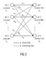
- FIG. 2 is a schematic representation of the channels or links between the respective base stations BSs and the user equipment UEs, wherein the direct links and the interfering links together with the associated channel matrices H are shown.
- Each base station uses a precoder F 1 to F K , wherein by means of joint precoding, the inter-cell interference, especially for cell-edge users may be reduced or even canceled.
- respective receive filters G 1 to G K are used.
- the precoders F 1 to F K need to be designed such that the rate of the edge-users is maximized. Designing the precoders and the receive filters separately, in general, leads to a suboptimal solution and consequently to low user rates.
- the data rates obtained are good, the computational complexity is high and it is necessitated to have knowledge about the interfering links at the base stations.
- the Max-SINR algorithm has the goal to maximize the signal-to-interference-ratio at the receivers.
- the precoding and receiving matrices are jointly designed. The performance, i.e. the obtainable data rates, is better when compared to the interference leakage algorithm, however, the computational complexity is higher and global channel knowledge needs to be available at the base stations, i.e. knowledge about the interfering links and the direct links.
- the receive filters need to be re-calculated every time the precoders change.
- interference alignment is based on the idea that unintended interference at each receiver can be forced to lie in only a subspace of the received signal; thus leaving another interference-free subspace which can be used for intended signal transmission. For example, if a receiver has two antennas, the unintended interference can be forced to lie in a one-dimensional subspace, leaving another subspace (also a one-dimensional subspace) to be interference-free.
- Interference alignment may be of specific interest when the antenna configuration of the system (the number of transmit and receive antennas) does not allow for a zero-forcing precoder design in accordance with which interference is pre-canceled at the transmitter side. In such a case IA offers an attractive alternative by first aligning the interference at each receiver by proper precoding at the transmitter side and then applying zero-forcing receive filters in order to cancel it.
- a system model will be considered having a K-user MIMO interference channel (IC) with K ⁇ 3 and where a user denotes a transmitter/receiver pair.
- IC K-user MIMO interference channel
- a user denotes a transmitter/receiver pair.
- K cells K cell-edge users which are served using the same resource blocks; thus, each cell-edge user experiences interference from K ⁇ 1 cells.
- Each transmitter is equipped with M antennas while each receiver is equipped with N antennas.
- a receiver desires to receive 1 ⁇ d ⁇ min(N, M) data symbols (streams).
- the data symbols s k ⁇ N J (O, I d ) ⁇ C d are precoded at a transmitter k by the linear precoder F k ⁇ C M ⁇ d , are sent over the direct channel H kk ⁇ C N ⁇ M , and are received by receiver k.
- the obtained signal is perturbed by noise n k ⁇ N C (O,C n k ) ⁇ C N in addition to unintended interference coming from other transmitters l ⁇ k.
- a receive filter G k ⁇ C N ⁇ d is employed to reduce or cancel the interference and/or maximize the achievable rate.
- the estimates of the data symbols received at the receiver k via the direct channel from transmitter k are given as follows:
- H kl ⁇ C N ⁇ M denotes the channel between the receiver k and the transmitter l.
- rank (H kl ) min(N, M), ⁇ k, l. In the present case, this constraint is relaxed to (H kl ) ⁇ d.
- the total achievable rate of all users R is given by:
- Equation (1) may be rewritten as follows:
- R k can then be written as follows:
- the first condition simply states that interference from all unintended transmitters should be suppressed, while the second one states that the design of the precoders and the receive filters needs to ensure the existence of an effective interference-free channel between the k-th transmitter/receiver pair where d data symbols (streams) can be simultaneously communicated.
- Both methods are based on the concept of network reciprocity, a concept which holds for Time Division Duplex (TDD) based systems. Due to the reciprocity, the signaling dimensions along which a receiving node sees the least interference from transmit signals are also the same dimensions along which the node will cause the least interference to other nodes in the reciprocal network where the roles of transmitters and receivers are switched.
- TDD Time Division Duplex
- H lk r H kl H (5)
- equation (6) becomes equivalent to equation (4) which tells that the alignment is reciprocal.
- alignment in the reciprocal networks can be achieved if it can be achieved in the original network
- interference alignment in the reciprocal network can be achieved by choosing the precoding and receive filters of the reciprocal network to be the receive and precoding filters of the original network.
- the signals are not separated in space; rather, at each step of the algorithm, it is tried to minimize the interference leakage (power) at each receiver such that the first condition of equation (4) is fulfilled when the algorithm converges. If interference power is zero, then interference coming from undesired transmitters is implicitly aligned to a smaller dimension.
- the interference leakage I k of receiver k in the original network due to all transmitters l ⁇ k is defined as:
- the columns of the receive filter that minimizes I k r are the eigenvectors corresponding to the d smallest eigenvalues of Q k r .
- the algorithm alternates between the original and reciprocal networks. Within each network the receivers update their receive filters such that the interference leakage is minimized. Arbitrary initial orthonormal precoders may be chosen as a starting point, and details of the algorithm for interference alignment via minimizing interference leakage are depicted in FIG. 3 .
- the channel state information (CSI) between receivers and undesired transmitters need to be available (i.e., the quantities H kl , ⁇ k, ⁇ l ⁇ k).
- the CSI of the direct links is not needed.
- an alternating optimization over both the precoding and receive filters is performed; with the precoders fixed, the receive filters are updated, and vice versa.
- the precoders are exchanged between the transmitters and channel matrices of the original network are used in the optimization process.
- the receive filters are exchanged between the transmitters and the channel matrices of the reciprocal network are used in the optimization process.
- the second algorithm aims at directly maximizing the Signal-to-Interference-Noise (SINR) ratio of each desired transmitted stream.
- SINR Signal-to-Interference-Noise
- SINR k , j G k : , j , H ⁇ H kk ⁇ F k : , j ⁇ F k : , j , H ⁇ H kk H ⁇ G k : , j G k : , j , H ⁇ B k , j ⁇ G k : , j ⁇ E tx , k d ( 11 )
- F k :,j is the j-th column of F k
- B k,j is the interference plus noise covariance matrix of the j-th stream of the k-th receiver:
- This algorithm necessitates global channel knowledge to be implemented, i.e., every transmitter should know the CSI of both the direct links and the interfering links.
- This algorithm can be implemented in a distributed fashion where the precoders and receive filters are iteratively exchanged between the transmitters, similar to the first algorithm. Similar to the first algorithm, an alternating optimization over both the precoding and receive filters may be performed.
- a method for reducing interference at a terminal of a wireless cellular network, the terminal experiencing interference from a plurality of interfering nodes in the wireless cellular network may have the step of: selecting the precoders of the interfering nodes such that the sum of distances between the interference projector matrices for the terminal is minimized.
- Another embodiment may have a non-transitory computer program product including instructions stored on a machine-readable medium for performing the inventive method, when the instructions are executed on a computer.
- a wireless cellular network may have: a plurality of nodes; and a terminal experiencing interference from at least some of the plurality of nodes, wherein the wireless cellular network is configured to provide for a selection of the precoders of nodes interfering with the terminal such that the sum of distances between the interference projector matrices for the terminal is minimized.
- Another embodiment may have a node of a wireless cellular network, wherein the wireless cellular network includes a terminal experiencing interference from the node and from one or more other interfering nodes in the network, wherein the precoders of the interfering nodes are selected such that the sum of distances between the interference projector matrices for the terminal is minimized, and wherein, after each iteration, the node is configured to calculate its precoder, to update its projector matrix accordingly, and to signal its updated projector matrix to all other interfering nodes.
- Another embodiment may have a central node for a wireless cellular network including a plurality of nodes, a backhaul network connecting the plurality of nodes and the central node, and a terminal experiencing interference from a plurality of interfering nodes in the wireless cellular network, wherein the central node is configured to select the precoders of the interfering nodes such that the sum of distances between the interference projector matrices for the terminal is minimized.
- Embodiments of the invention provide a method for reducing interference at a terminal of a wireless cellular network, the terminal experiencing interference from a plurality of interfering nodes in the wireless cellular network, the method comprising selecting the precoders of the interfering nodes such that the sum of distances between the interference projector matrices for the terminal is minimized.
- the interference projector matrix may correspond to a unique receive interference subspace between the terminal and the interfering node.
- the interference projector matrix may be a function of the precoder matrix of the interfering node and the channel matrix of the channel from the interfering node to the terminal.
- the wireless cellular network may comprise a plurality of terminals, wherein the precoders are designed such that the sum of distances of the interference projector matrices over all terminals is minimized.
- the precoders of the interfering nodes may be designed as follows:
- the receive interference subspaces may be adjusted iteratively until an alignment of the receive interference subspace is reached.
- the precoders may be calculated by an alternating minimization algorithm, wherein at each iteration one precoder is calculated using a predefined method and its corresponding projector matrices are updated, wherein the next precoder is calculated based on the updated projector matrices, until convergence.
- F m ⁇ m ⁇ l an optimal precoder F t,opt is chosen as follows:
- F l , opt argmin F l ⁇ ⁇ k ⁇ l ⁇ ⁇ ⁇ m ⁇ ⁇ l , k ⁇ ⁇ ⁇ ⁇ P kl - P km ⁇ F 2
- index k refers to the receivers/terminals
- indices l,m refer to the transmitters/interfering nodes
- projector matrix P kl depends on precoder F l
- P km depends on precoder F m
- ⁇ P kl ⁇ P km ⁇ F is the Frobenius norm of P kl ⁇ P km .
- the nodes may be connected over a backhaul network, and the iterative calculation may be performed in a central node of the wireless cellular network, or wherein the iterative calculation may be distributed over a plurality of nodes of the wireless cellular network.
- a receive filter in the terminal may be selected independent of the design of the precoders at the interfering nodes.
- a minimum mean-square-error (MMSE), an interference-rejection-combining (IRC) or a zero-forcing (ZF) receiving filter may be chosen.
- Embodiments of the invention provide a non-transitory computer program product comprising instructions stored on a machine-readable medium for performing the inventive method, when the instructions are executed on a computer.
- Embodiments of the invention provide a wireless cellular network, comprising a plurality of nodes, and a terminal experiencing interference from at least some of the plurality of nodes, wherein the wireless cellular network is configured to provide for a selection of the precoders of nodes interfering with the terminal such that the sum of distances between the interference projector matrices for the terminal is minimized.
- the wireless cellular network may comprise a backhaul network connecting the plurality of nodes, wherein the plurality of nodes are adapted to provide for a calculation of the precoders distributed among the plurality of nodes.
- the wireless circular network may comprise a central node; and a backhaul network connecting the plurality of nodes and the central node, wherein the central node is configured to provide for a centralized calculation of the precoders for the interfering nodes.
- Embodiments of the invention provide a node of a wireless cellular network, wherein the wireless cellular network comprises a terminal experiencing interference from the node and from one or more other interfering nodes in the network, wherein the precoders of the interfering nodes are selected such that the sum of distances between the interference projector matrices for the terminal is minimized, wherein the node is configured to calculate its precoder and to update its projector matrix accordingly; and wherein the node is configured to signal its updated projector matrix to the one or more other interfering nodes.
- Embodiments of the invention provide a central node for a wireless cellular network comprising a plurality of nodes, a backhaul network connecting the plurality of nodes and the central node, and a terminal experiencing interference from a plurality of interfering nodes in the wireless cellular network, wherein the central node is configured to select the precoders of the interfering nodes such that the sum of distances between the interference projector matrices for the terminal is minimized.
- node base station
- this is considered as an interfering node for one or more terminals.
- the base station is an interfering node for more than one terminal, it is necessitated to calculate also a plurality of projector matrices.
- a novel approach for suppressing interference at a mobile terminal, for example at an edge-user, in a wireless cellular network is presented, whereas, contrary to the conventional approaches, interference alignment is obtained without the need for taking “action” at both “ends” of the transmission path, i.e., both at the interfering base station and at the receiver, rather in accordance with the inventive approach it is sufficient to select the precoders at the interfering base station in such a way that in the distance between the interference projector matrices for the terminal is minimized.
- the novel interference alignment (IA) algorithm achieves IA with a precoder design only. A new formulation with more geometrical insights to the IA problem is presented.
- the design based on the precoders simplifies the problem structure extensively and allows receive filters to be designed independently and irrespectively of the IA conditions. Simulation results show that the proposed scheme results in higher data rates for cell-edge users (given the same CSI knowledge assumption) with less signaling overhead.
- the inventive approach provides a new formulation to the IA problem in terms of the precoding matrices only.
- the subspace occupied by the interference from an undesired base station is modeled with a projector matrix, also called “interference projector”.
- This projector matrix implicitly depends on a precoder of the undesired base station.
- There is a one-to-one correspondence between a subspace and its projector matrix i.e., for each subspace there is a unique corresponding projector matrix. If at one UE, the distance between two interference projectors (corresponding to two interfering signals from two different base stations) is zero, these subspaces are aligned, and interference is aligned into one subspace.
- the precoders of the different base stations are optimized such that the sum of distances of interference projectors over all receivers is minimized.
- An optimized solution gives a sum of zero.
- the solution to the problem is found in an iterative manner where at each iteration, one precoder is calculated, its corresponding projector matrices are updated and communicated to the other base stations, and this process is repeated until convergence.
- the receive filters are not part of the optimization process; this additional degree of freedom allows to freely select the receive filters according to the scenario at hand. In accordance with embodiments, it may be necessitated to have knowledge of the CSI (Channel State Information) of the interfering links.
- CSI Channel State Information
- the inventive approach is advantageous as it allows separating the design of the precoders and the receive filters without any degradation in performance. It even results in higher achievable user rates for edge-users given the same CSI knowledge assumption. Since the receive filters are independent of the precoders or the precoding filters, simple minimum means squared error (MMSE) or interference rejection combining (IRC) filters may be used, as they are, for example, specified in the standard. In contrast, state-of-the-art methods necessitate the use of complex receive filters which makes these methods hard to implement in real scenarios. Further, the inventive approach is advantageous as it results in a reduced signaling overhead over the air-link.
- MMSE minimum means squared error
- IRC interference rejection combining
- FIG. 1 shows a schematic representation of a wireless cellular network comprising K cells
- FIG. 2 is a schematic representation of the direct links and the interfering links between the base stations BSs and the user equipment UEs of FIG. 1 ;
- FIG. 3 shows an algorithm for interference alignment via minimizing interference leakage
- FIG. 4 shows the Max-SINR algorithm
- FIG. 5 shows a schematic representation of a part of a wireless cellular network, wherein FIG. 5A shows the network before the IA design, and FIG. 5B shows the network after the IA design;
- FIG. 6 shows the modified steepest descent algorithm on the Grassmann manifold
- FIG. 7 shows the algorithm for interference alignment via minimizing projector distances of different subspaces in accordance with an embodiment of the invention
- FIG. 8 is a graph showing the spectral efficiency results for a first scenario
- FIG. 9 is a graph showing the spectral efficiency results for a second scenario
- FIG. 10 is a graph showing the effect of using MMSE versus ZF filters on performance.
- FIG. 11 is a graph showing the effect of WF on the performance.
- a separate design of precoders and receive filters without any degradation and system performance is performed. This is done by using the concept of interference alignment and by designing the precoders such that the interfering signals at each user equipment coming from different base stations have the same direction of arrival as the user equipment so that multiple interference signals overlap.
- FIG. 5 shows a schematic representation of a part of a wireless cellular network on the basis of which the concept of interference alignment is described, wherein FIG. 5A shows the network before the IA design, and FIG. 5B shows the network after the IA design.
- the schematically represented network comprises three cells I-III, each including a base station BS 1 to BS 3 .
- FIG. 5A in each cell a respective user UE 1 to UE 3 is depicted.
- the users are located close to an edge of the respective cells, i.e. the users UE 1 to UE 3 are considered cell-edge users.
- the user UE 3 in cell III is considered with regard to interference signals received from base stations BS 1 and BS 2 .
- FIG. 5 shows a schematic representation of a part of a wireless cellular network on the basis of which the concept of interference alignment is described, wherein FIG. 5A shows the network before the IA design, and FIG. 5B shows the network after the IA design.
- the schematically represented network comprises three cells
- the interfering signals from the respective base stations are shown as dotted arrows. Further, for base stations BS 1 and BS 2 a graphical/spatial representation of the precoding at the respective base station is indicated by lobes L 11 to L 22 .
- the precoding at base station BS 1 and at base station BS 2 ensure that the respective users UE 1 and UE 2 , respectively, are served by the base stations, as is shown by the solid line arrows.
- the filtering is also graphically/spatially represented by the lobes L 31 and L 32 . It is noted that the lobes shown in FIG. 5 are an illustrative example when the UE has two antennas (and therefore two lobes). For example, when a UE has three antennas, there would be three lobes.
- FIG. 5A shows a situation without interference alignment.
- the precoding at the base stations BS 1 and BS 2 , and the filtering at user UE 3 is such that for example only the interfering signal from base station BS 1 can be canceled at the user UE 3 , whereas an interference signal from base station BS 2 cannot be canceled.
- the precoders are designed in such a way that the interfering signals at the user coming from different base stations have the same direction, an approach that is schematically shown in FIG. 5B showing the network of FIG. 5A after applying the concept of interference alignment.
- FIGS. 5A and 5B show the interfering signals from both base stations BS 1 and BS 2 now have the same direction of arrival at the user equipment UE 3 , and when compared to FIG.
- the interference signal from the second base station BS 2 now arrives in the same direction as the interference signal from the base station BS 1 so that it is now possible to cancel both interfering signals from both base stations BS 1 and BS 2 .
- the multiple interfering signals now appear as one signal so that they can easily be canceled.
- this interference alignment operates such that the precoders at the base stations are designed such that the sum of the distances of the interference of the interference projector matrices of all user equipment is minimized as follows:
- the precoders are calculated iteratively.
- Receive filters are excluded from the optimization problems so that it is possible to use any desired receive filters, like MMSE, IRC or ZF filters as they are specified in the standard on the basis of which the cellular network operates.
- a distance of 0 between two subspaces means that these subspaces are aligned, i.e. they constitute the same identical subspace.
- P k,l is defined to be the orthogonal projector onto the column space of H kl F l , ⁇ l, ⁇ k ⁇ l.
- P k,l has the following properties which are necessitated later:
- the one-sided interference alignment problem may be formulated as the problem of finding the optimal precoders that minimize the sum of distances between interfering subspaces of all receivers:
- ⁇ upper is reformulated as follows:
- the optimal precoder F l,opt is chosen as follows:
- F l , opt argmin F l ⁇ ⁇ k ⁇ l ⁇ ⁇ ⁇ m ⁇ ⁇ l , k ⁇ ⁇ ⁇ ⁇ P kl - P km ⁇ F 2 . ⁇ ⁇ upper , l ( 21 )
- ⁇ upper,l is composed of a sum of generalized Rayleigh quotients, whose minimizer does not have a closed form solution. Therefore, numerical techniques will be used, as is described below, to find a solution to the above problem.
- equation (22) is invariant to multiplication by unitary matrices follows along the same line as above.
- the invariance to unitary rotations means that the optimal solution only depends on the subspace in which the precoder lies and not on the precoder itself.
- This very useful property of the objective function implies that it can be minimized on the complex Grassmann manifold of the space C M ⁇ d .
- the complex Grassmann manifold of the C M ⁇ d (d ⁇ M) space is defined as the set of all d-dimensional complex subspaces of C M , as is described for example in J. H.
- FIG. 7 shows the algorithm for interference alignment via minimizing projector distances of different subspaces in accordance with an embodiment of the present invention.
- F l , opt arg ⁇ ⁇ min F l ⁇ ⁇ k ⁇ l ⁇ ⁇ m ⁇ ⁇ l , k ⁇ ⁇ ⁇ P kl - P km ⁇ F 2 ⁇ ⁇ upper , l .
- the index k refers to the receivers, while indices m,l refer to the transmitters.
- the projector P kl implicitly depends on precoder F l , while the projector P km depends on precoder F m .
- the solution F l,opt can be obtained using the steepest descent algorithm on the Grassmann manifold as described above.
- Equal power is allocated to each stream, assuming the CSI of the direct link between the k-th transmitter/receiver pair being not available.
- the optimal power allocation can be obtained according to the water-filling approach (WF), as for example described in E. Biglieri, R. Calderbank, A. Constantinides, A. Goldsmith, A. Paulraj and H. Vincent Poor, MIMO Wireless Communications, Cambridge University Press, 2007.
- WF water-filling approach
- R k can be simplified to.
- R k log 2 det( I d + ⁇ k ⁇ k H ( G k H C n k G k ) ⁇ 1 ) (26)
- equation (3) was still used in order to account for the case where interference is not perfectly aligned.
- MMSE filters may be advantageous due to their better performance when compared to ZF filters, and they may be more robust to channel estimation errors. Even though an MMSE filter violates the IA conditions (see equation (4) above), its use results in higher achievable rates since it takes noise statistics into account. In this case, the filter expression is given by;
- the MMSE filter is derived as follows. As its name implies, an MMSE filter minimizes the mean squared error between the transmitted and the received symbols:
- G mmse , k arg ⁇ ⁇ min G k ⁇ E ⁇ [ ⁇ s k - s ⁇ k ⁇ 2 2 ] .
- the approach in accordance with embodiments of the invention for achieving the interference alignment is an alternating minimization algorithm, with each iteration one precoder is calculated using the steepest descent method and its corresponding projector matrices are updated. With the updated projector matrices the next precoder is calculated and this continues until convergence.
- embodiments of the invention allow for a CoMP approach calculating optimal precoding matrices in wireless cellular networks via minimizing the sum of distances of interference projectors.
- An iterative procedure may be used whereby at each iteration, the optimal precoding matrices are calculated based on exchanging the interference projector matrices between base stations. The calculation may be performed in a centralized unit or in a distributed way over the base stations necessitating signaling over the backhaul network which connects the base stations.
- the receive filters may be chosen according to the desired specifications, for example, they may be chosen to be MMSE, IRC or ZF filters.
- the CSI between the receivers and undesired transmitters is available.
- a precoder design is necessitated to achieve interference alignment, in contrast to conventional methods in which both precoders and receive filters are part of the optimization process.
- the algorithm may be implemented in a centralized as well as in a distributed fashion.
- a distributed implementation necessitates that the updated projectors corresponding to the receive interference subspaces are exchanged between the transmitters. While conventional approaches necessitate the calculated receive filters to be signaled from the base station to the user side, which takes place over the air-link, the proposed method has no such requirements and thus results in less signaling over the air-link.
- FIG. 8 shows the spectral efficiency results for the first scenario.
- the inventive approach beats the IA algorithm via minimizing interference leakage, but has a lower performance than the Max-SINR algorithm.
- the Max-SINR necessitates more signaling overhead.
- the latter necessitates complete channel knowledge, which means all nine channels have to be fed back to the transmitter.
- the remaining algorithms only necessitate the cross-links to be exchanged (six channels).
- FIG. 9 shows the spectral efficiency results for the second scenario.
- the algorithm in accordance with embodiments of the invention beats both conventional algorithms starting at SNR of 13 dB, where
- FIG. 10 shows the effect of using MMSE versus ZF filters on performance, assuming the above-mentioned second scenario.
- MMSE filters offer only small performance gains since perfect CSI at the transmitters is assumed. In more realistic scenarios, where only imperfect CSI is available at the transmitter side, MMSE filters are expected to offer a larger performance gain.
- FIG. 11 shows the effect of WF on the performance.
- WF provides gains in the low SNR scheme only; at medium and high SNR levels the WF algorithm performs as if equal power was allocated to the different streams.
- aspects have been described in the context of an apparatus, it is clear that these aspects also represent a description of the corresponding method, where a block or device corresponds to a method step or a feature of a method step. Analogously, aspects described in the context of a method step also represent a description of a corresponding block or item or feature of a corresponding apparatus.
- embodiments of the invention can be implemented in hardware or in software.
- the implementation can be performed using a digital storage medium, for example a floppy disk, a DVD, a CD, a ROM, a PROM, an EPROM, an EEPROM or a FLASH memory, having electronically readable control signals stored thereon, which cooperate (or are capable of cooperating) with a programmable computer system such that the respective method is performed.
- Some embodiments according to the invention comprise a data carrier having electronically readable control signals, which are capable of cooperating with a programmable computer system, such that one of the methods described herein is performed.
- embodiments of the present invention can be implemented as a computer program product with a program code, the program code being operative for performing one of the methods when the computer program product runs on a computer.
- the program code may for example be stored on a machine readable carrier.
- Other embodiments comprise the computer program for performing one of the methods described herein, stored on a machine readable carrier.
- an embodiment of the inventive method is, therefore, a computer program having a program code for performing one of the methods described herein, when the computer program runs on a computer.
- a further embodiment of the inventive methods is, therefore, a data carrier (or a digital storage medium, or a computer-readable medium) comprising, recorded thereon, the computer program for performing one of the methods described herein.
- a further embodiment of the inventive method is, therefore, a data stream or a sequence of signals representing the computer program for performing one of the methods described herein. The data stream or the sequence of signals may for example be configured to be transferred via a data communication connection, for example via the Internet.
- a further embodiment comprises a processing means, for example a computer, or a programmable logic device, configured to or adapted to perform one of the methods described herein.
- a further embodiment comprises a computer having installed thereon the computer program for performing one of the methods described herein.
- a programmable logic device for example a field programmable gate array
- a field programmable gate array may cooperate with a microprocessor in order to perform one of the methods described herein.
- the methods are performed by any hardware apparatus.
Landscapes
- Engineering & Computer Science (AREA)
- Computer Networks & Wireless Communication (AREA)
- Signal Processing (AREA)
- Power Engineering (AREA)
- Quality & Reliability (AREA)
- Physics & Mathematics (AREA)
- Electromagnetism (AREA)
- Mobile Radio Communication Systems (AREA)
Abstract
Description
where HklεC N×M denotes the channel between the receiver k and the transmitter l. Conventionally, it is assumed that rank (Hkl)=min(N, M), ∀k, l. In the present case, this constraint is relaxed to (Hkl)≧d.
where Rk is the achievable rate of user k. Equation (1) may be rewritten as follows:
where Ĥk=Gk HHkkFk and Ĥint,l=Gk HHklFl denote the effective direct channel between the k-th transmitter/receiver pair and the effective interfering channel between the transmitter l and receiver k, respectively. Rk can then be written as follows:
G k H H kl F l=0, ∀l≠k
rank(G k H H kk F k)=d. (4)
Hlk r=Hkl H (5)
G l r,H H lk r F k r=0, ∀k≠l
rank(G k r,H H kk r F k r)=d. (6)
is the interference covariance matrix of receiver k. For given precoders, the columns of the receive filter that minimizes Ik are the eigenvectors corresponding to the d smallest eigenvalues of Qk, that is:
G k :,l=vl(Q k), (9)
is the interference covariance matrix of receiver k. Similarly, the columns of the receive filter that minimizes Ik r are the eigenvectors corresponding to the d smallest eigenvalues of Qk r.
where Fk :,j is the j-th column of Fk and Bk,j is the interference plus noise covariance matrix of the j-th stream of the k-th receiver:
P kl =H kl F l(F l H H kl H H kl F l)−1 F l H H kl H.
wherein
- F1, . . . , FK=precoder matrices of interfering
nodes 1 to K, - Pkl=interference projector matrix corresponding to an interference subspace between an interfering node l and a terminal k,
- Pkm=interference projector matrix corresponding to an interference subspace between an interfering node m and the terminal k,
- ∥Pkl−Pkm∥2=distance between interference projector matrices.
wherein index k refers to the receivers/terminals, while indices l,m refer to the transmitters/interfering nodes, wherein projector matrix Pkl depends on precoder Fl, and wherein Pkm depends on precoder Fm, and wherein ∥Pkl−Pkm∥F is the Frobenius norm of Pkl−Pkm.
wherein
- Fl, . . . , FK=precoder matrices of interfering
nodes 1 to K, - Pkl=interference projector matrix corresponding to an interference subspace between an interfering node l and a terminal k,
- Pkm=interference projector matrix corresponding to an interference subspace between an interfering node m and a terminal k,
- ∥Pkl−Pkm∥2=distance between interference projector matrices.
- K=number of base stations.
d(S 1 ,S 2)=∥P 1 −P 2∥2, (14)
where Pi is the orthogonal projector onto Si, and ∥[∥2 the 2-norm of a matrix. The 2-norm of a matrix A is defined as:
∥A∥ 2=σmax(A),
which is the maximum singular value of A. Moreover, the following inequalities hold:
∥A∥2≦∥A∥F≦√{square root over (n)}∥A∥2, (15)
where ∥A∥F is the Frobenius norm of A, and n is the number of columns of the matrix A.
P kl =H kl F l(F l H H kl H H kl F l)−1 F l H H kl H, (16)
where (●)H denotes the conjugate transposition.
- 1. Pkl=Pkl 2.
- 2. Pkl=Pkl H.
- 3. tr(Pkl)=d.
where the identity tr(AB)=tr(BA) which holds for any matrices A and B has been used.
and instead of minimizing α the upper bound αupper may be minimized so that the problem becomes:
with the implicitly defined and known quantities Ak and Bk, then using the linearity property of the trace, sum and derivative operators in addition to the chain rule property, the derivative of αupper,l w.r.t, Fl* is calculated as follows:
where the last equation follows from K. B. Petersen and M. S. Pedersen, “The Matrix Cookbook”, http:/matrixcookbook.com.
f(X)=f(XQ)for initary QεC d×d (C1)
f(X)=f(XQ)for invertible QεC d×d (C2)
The details of the algorithm are shown in
Fl′=FlPl, (25)
where PlεCd×d is a diagonal matrix with diagonal elements equal to
This ensures that the power constraint is satisfied. Moreover, it does not ruin the alignment conditions due to the invariance of the local interference alignment objectives to multiplications by invertible matrices, as has been described above.
R k=log2 det(I d +Ĥ k Ĥ k H(G k H C n
and consequently:
where E[sksl H]=0, ∀l≠k (different symbols are uncorrelated) as well as E[slnk H]=0, ∀l,k (symbols and noise are uncorrelated) have been used. The objective function is convex in Gk; thus, the minimizer can be found by setting the derivative of the objective βk w.r.t. Gk* (or Gk) to 0:
and it is assumed that noise statistics are similar at difference receivers for simplicity. It is assumed that this is the case because conventional algorithms are based on the concept of reverse networks, and, thus, a filter that improves IA quality or the SINR in one direction can ruin IA quality or the SINR in the other direction. Therefore, these algorithms can only find a local solution or not even reach one. A convergence proof for the IA scheme based on minimizing interference leakage was given, but no convergence proof was presented for the Max-SINR algorithm. On the other hand, the inventive approach can easily be shown to converge since it is an alternating minimizing algorithm.
Claims (21)
P kl =H kl F l(F l H H kl H H kl F l)−1 F l H H kl H.
Applications Claiming Priority (4)
| Application Number | Priority Date | Filing Date | Title |
|---|---|---|---|
| EP12155149.3 | 2012-02-13 | ||
| EP12155149.3A EP2627050B1 (en) | 2012-02-13 | 2012-02-13 | Method for reducing interference at a terminal of a wireless cellular network, wireless cellular network, node and central node of a wireless network |
| EP12155149 | 2012-02-13 | ||
| PCT/EP2013/052292 WO2013120741A1 (en) | 2012-02-13 | 2013-02-06 | Method for reducing interference at a terminal of a wireless cellular network, wireless cellular network, node and central node of a wireless network |
Related Parent Applications (1)
| Application Number | Title | Priority Date | Filing Date |
|---|---|---|---|
| PCT/EP2013/052292 Continuation WO2013120741A1 (en) | 2012-02-13 | 2013-02-06 | Method for reducing interference at a terminal of a wireless cellular network, wireless cellular network, node and central node of a wireless network |
Publications (2)
| Publication Number | Publication Date |
|---|---|
| US20130237261A1 US20130237261A1 (en) | 2013-09-12 |
| US9184813B2 true US9184813B2 (en) | 2015-11-10 |
Family
ID=47678814
Family Applications (1)
| Application Number | Title | Priority Date | Filing Date |
|---|---|---|---|
| US13/857,440 Expired - Fee Related US9184813B2 (en) | 2012-02-13 | 2013-04-05 | Method for reducing interference at a terminal of a wireless cellular network, wireless cellular network, node and central node of a wireless network |
Country Status (5)
| Country | Link |
|---|---|
| US (1) | US9184813B2 (en) |
| EP (1) | EP2627050B1 (en) |
| JP (1) | JP5671634B2 (en) |
| CN (1) | CN103703731B (en) |
| WO (1) | WO2013120741A1 (en) |
Cited By (1)
| Publication number | Priority date | Publication date | Assignee | Title |
|---|---|---|---|---|
| US20140036815A1 (en) * | 2012-08-03 | 2014-02-06 | Agency For Science, Technology And Research | Method for determining precoding matrixes for communication and a system therefrom |
Families Citing this family (21)
| Publication number | Priority date | Publication date | Assignee | Title |
|---|---|---|---|---|
| US9735940B1 (en) | 2012-04-12 | 2017-08-15 | Tarana Wireless, Inc. | System architecture for optimizing the capacity of adaptive array systems |
| US9252908B1 (en) | 2012-04-12 | 2016-02-02 | Tarana Wireless, Inc. | Non-line of sight wireless communication system and method |
| KR20140000847A (en) * | 2012-06-26 | 2014-01-06 | 삼성전자주식회사 | Apparatus and method for interference aligment in wireless communication system |
| US10110270B2 (en) | 2013-03-14 | 2018-10-23 | Tarana Wireless, Inc. | Precision array processing using semi-coherent transceivers |
| US10499456B1 (en) | 2013-03-15 | 2019-12-03 | Tarana Wireless, Inc. | Distributed capacity base station architecture for broadband access with enhanced in-band GPS co-existence |
| US20140294109A1 (en) * | 2013-04-01 | 2014-10-02 | Electronics And Telecommunications Research Institute | Method and apparatus for opportunistic interference alignment (oia) in single-user multiple-input multiple-output (su-mimo) transmission |
| KR102154273B1 (en) * | 2013-05-21 | 2020-09-09 | 한국전자통신연구원 | Apparatus and method for aligning partial interference on communication system with multi-antenna |
| US9509379B2 (en) * | 2013-06-17 | 2016-11-29 | Huawei Technologies Co., Ltd. | System and method for designing and using multidimensional constellations |
| KR102130285B1 (en) * | 2013-12-26 | 2020-07-08 | 삼성전자주식회사 | The method and apparatus for zero-forcing hybrid beamforming |
| US10348394B1 (en) * | 2014-03-14 | 2019-07-09 | Tarana Wireless, Inc. | System architecture and method for enhancing wireless networks with mini-satellites and pseudollites and adaptive antenna processing |
| WO2015152777A1 (en) * | 2014-04-03 | 2015-10-08 | Telefonaktiebolaget L M Ericsson (Publ) | A network node and a method therein for estimating a convergence time of interference processing in a user equipment in a radio communications network |
| US9467212B2 (en) | 2014-05-09 | 2016-10-11 | Huawei Technologies Canada Co., Ltd. | System and method for multiple-input multiple-output communication |
| US10523383B2 (en) | 2014-08-15 | 2019-12-31 | Huawei Technologies Co., Ltd. | System and method for generating waveforms and utilization thereof |
| CN104184689B (en) * | 2014-08-15 | 2017-12-19 | 电子科技大学 | The blind interference alignment method of SISO systems |
| CN104540209B (en) * | 2014-12-01 | 2018-04-06 | 国家电网公司 | A kind of method for lifting interference alignment network transmission speed |
| KR102323475B1 (en) * | 2015-04-20 | 2021-11-09 | 한국전자통신연구원 | Method for inference alignment for uplink in wireless local area network system, access point and user terminal for performing the same |
| WO2017071586A1 (en) | 2015-10-30 | 2017-05-04 | Huawei Technologies Co., Ltd. | System and method for high-rate sparse code multiple access in downlink |
| US9942020B1 (en) * | 2017-04-26 | 2018-04-10 | Cisco Technology, Inc. | Minimum delay spatio-temporal filtering for interference rejection |
| CN109962728B (en) * | 2019-03-28 | 2021-01-26 | 北京邮电大学 | Multi-node joint power control method based on deep reinforcement learning |
| CN113711666B (en) * | 2019-04-26 | 2024-06-07 | 株式会社Ntt都科摩 | Wireless communication node |
| US11025399B2 (en) * | 2019-05-02 | 2021-06-01 | Nokia Technologies Oy | Interference suppression |
Citations (3)
| Publication number | Priority date | Publication date | Assignee | Title |
|---|---|---|---|---|
| US20110045782A1 (en) * | 2009-08-18 | 2011-02-24 | Samsung Electronics Co., Ltd. | Devices and methods for transmitting and receiving data using precoding matrix |
| US20110287790A1 (en) * | 2008-12-08 | 2011-11-24 | Thomas Haustein | Mobile Communication Device, Network Node, Communication System and Method for Distributed Cooperative Multi-Antenna Communication |
| US20130182672A1 (en) * | 2010-08-16 | 2013-07-18 | Ntt Docomo, Inc. | Mobile terminal apparatus and radio communication method |
Family Cites Families (5)
| Publication number | Priority date | Publication date | Assignee | Title |
|---|---|---|---|---|
| US6574293B1 (en) * | 1998-10-28 | 2003-06-03 | Ericsson Inc. | Receivers and methods for reducing interference in radio communications |
| US7433332B2 (en) * | 2003-04-30 | 2008-10-07 | Skypipes Wireless, Inc. | Managed microcell wireless mesh network architecture |
| EP2363964B1 (en) * | 2010-02-26 | 2013-07-31 | Alcatel Lucent | Sub-channel transmission mode modification |
| US8472550B2 (en) * | 2010-12-23 | 2013-06-25 | Mitsubishi Electric Research Laboratories, Inc. | Method for reducing interference in multi-cell multi-user wireless networks |
| JP5756636B2 (en) * | 2011-01-11 | 2015-07-29 | シャープ株式会社 | Wireless communication system, receiver, transmitter |
-
2012
- 2012-02-13 EP EP12155149.3A patent/EP2627050B1/en not_active Not-in-force
-
2013
- 2013-02-06 JP JP2013558475A patent/JP5671634B2/en not_active Expired - Fee Related
- 2013-02-06 WO PCT/EP2013/052292 patent/WO2013120741A1/en not_active Ceased
- 2013-02-06 CN CN201380000125.8A patent/CN103703731B/en not_active Expired - Fee Related
- 2013-04-05 US US13/857,440 patent/US9184813B2/en not_active Expired - Fee Related
Patent Citations (3)
| Publication number | Priority date | Publication date | Assignee | Title |
|---|---|---|---|---|
| US20110287790A1 (en) * | 2008-12-08 | 2011-11-24 | Thomas Haustein | Mobile Communication Device, Network Node, Communication System and Method for Distributed Cooperative Multi-Antenna Communication |
| US20110045782A1 (en) * | 2009-08-18 | 2011-02-24 | Samsung Electronics Co., Ltd. | Devices and methods for transmitting and receiving data using precoding matrix |
| US20130182672A1 (en) * | 2010-08-16 | 2013-07-18 | Ntt Docomo, Inc. | Mobile terminal apparatus and radio communication method |
Non-Patent Citations (4)
| Title |
|---|
| El Ayach, Omar et al., "The Feasibility of Interference Alignment Over Measured MIMO-OFDM Channels," IEEE Transactions on Vehicular Technology, vol. 59, No. 9, Nov. 2010, pp. 4309-4321. |
| Gomadam, Krishna et al., "Approaching the Capacity of Wireless Networks through Distributed Interference Alignment," IEEE Global Telecommunications Conference (GLOBECOM), 2008, 10 pages. |
| International Search Report and Written Opinion of the International Searching Authority in corresponding International Application No. PCT/EP2013/052292, dated Mar. 21, 2013, 13 pages. |
| Peters, Steven W. et al., "Interference Alignment Via Alternating Minimization," IEEE International Conference on Acoustics, Speech and Signal Processing (ICASSP), 2009, pp. 2445-2448. |
Cited By (2)
| Publication number | Priority date | Publication date | Assignee | Title |
|---|---|---|---|---|
| US20140036815A1 (en) * | 2012-08-03 | 2014-02-06 | Agency For Science, Technology And Research | Method for determining precoding matrixes for communication and a system therefrom |
| US9614599B2 (en) * | 2012-08-03 | 2017-04-04 | Agency For Science, Technology And Research | Method for determining precoding matrixes for communication and a system therefrom |
Also Published As
| Publication number | Publication date |
|---|---|
| EP2627050A1 (en) | 2013-08-14 |
| CN103703731B (en) | 2016-11-09 |
| US20130237261A1 (en) | 2013-09-12 |
| JP5671634B2 (en) | 2015-02-18 |
| CN103703731A (en) | 2014-04-02 |
| EP2627050B1 (en) | 2016-01-13 |
| WO2013120741A1 (en) | 2013-08-22 |
| JP2014514810A (en) | 2014-06-19 |
Similar Documents
| Publication | Publication Date | Title |
|---|---|---|
| US9184813B2 (en) | Method for reducing interference at a terminal of a wireless cellular network, wireless cellular network, node and central node of a wireless network | |
| Negro et al. | On the MIMO interference channel | |
| Khachan et al. | Linear processing for the downlink in multiuser MIMO systems with multiple data streams | |
| Fritzsche et al. | Robust sum rate maximization in the multi-cell MU-MIMO downlink | |
| US20180138951A1 (en) | Antenna selection for massive mimo systems related application | |
| US20200373975A1 (en) | Method and device for performing transmissions of data | |
| Park et al. | Regularized interference alignment based on weighted sum-MSE criterion for MIMO interference channels | |
| Fritzsche et al. | Distributed robust sum rate maximization in cooperative cellular networks | |
| Nosrat-Makouei et al. | User arrival in MIMO interference alignment networks | |
| Mosleh et al. | Interference alignment and leakage-based iterative coordinated beam-forming for multi-user MIMO in LTE-advanced | |
| Maciel et al. | A convex quadratic SDMA grouping algorithm based on spatial correlation | |
| Park et al. | Regularized transceiver designs for multi-user MIMO interference channels | |
| US20230125744A1 (en) | Multi-user pre-coding | |
| US12113594B2 (en) | Multi-user precoding | |
| Younas et al. | Achieving bandwidth efficiency by improved zero-forcing combining algorithm in massive MIMO | |
| Ghanem | Optimal power allocation and optimal precoding with multi-cell processing | |
| Lee et al. | Coordinated beamforming with relaxed zero forcing | |
| Bazzi et al. | Subspace precoding with limited feedback for the massive MIMO interference channel | |
| Bazzi et al. | Interference alignment with imperfect channel state information at the transmitter | |
| US9210006B2 (en) | Method for processing a data signal and receiver circuit | |
| Aquilina et al. | Beamformer design for interference alignment in full-duplex cellular networks with imperfect CSI | |
| González-Coma et al. | Multi-stream MIMO MSE balancing with generalized power constraints | |
| Razavi et al. | Interference alignment in coordinated multipoint systems | |
| Kumar et al. | Graph Neural Networks for Hybrid Beamforming in MIMO Rate Splitting Multiple Access | |
| Saeid et al. | On MU-MIMO precoding techniques for WiMAX |
Legal Events
| Date | Code | Title | Description |
|---|---|---|---|
| AS | Assignment |
Owner name: NTT DOCOMO, INC., JAPAN Free format text: ASSIGNMENT OF ASSIGNORS INTEREST;ASSIGNORS:BAZZI, SAMER;DIETL, GUIDO;UTSCHICK, WOLFGANG;SIGNING DATES FROM 20130627 TO 20130703;REEL/FRAME:031445/0379 |
|
| STCF | Information on status: patent grant |
Free format text: PATENTED CASE |
|
| CC | Certificate of correction | ||
| FEPP | Fee payment procedure |
Free format text: MAINTENANCE FEE REMINDER MAILED (ORIGINAL EVENT CODE: REM.); ENTITY STATUS OF PATENT OWNER: LARGE ENTITY |
|
| LAPS | Lapse for failure to pay maintenance fees |
Free format text: PATENT EXPIRED FOR FAILURE TO PAY MAINTENANCE FEES (ORIGINAL EVENT CODE: EXP.); ENTITY STATUS OF PATENT OWNER: LARGE ENTITY |
|
| STCH | Information on status: patent discontinuation |
Free format text: PATENT EXPIRED DUE TO NONPAYMENT OF MAINTENANCE FEES UNDER 37 CFR 1.362 |
|
| FP | Lapsed due to failure to pay maintenance fee |
Effective date: 20191110 |