US9173030B2 - Speaker system and speaker driving method - Google Patents
Speaker system and speaker driving method Download PDFInfo
- Publication number
- US9173030B2 US9173030B2 US12/556,017 US55601709A US9173030B2 US 9173030 B2 US9173030 B2 US 9173030B2 US 55601709 A US55601709 A US 55601709A US 9173030 B2 US9173030 B2 US 9173030B2
- Authority
- US
- United States
- Prior art keywords
- actuator
- speaker system
- speaker
- display screen
- plate part
- Prior art date
- Legal status (The legal status is an assumption and is not a legal conclusion. Google has not performed a legal analysis and makes no representation as to the accuracy of the status listed.)
- Expired - Fee Related, expires
Links
Images


Classifications
-
- H—ELECTRICITY
- H04—ELECTRIC COMMUNICATION TECHNIQUE
- H04R—LOUDSPEAKERS, MICROPHONES, GRAMOPHONE PICK-UPS OR LIKE ACOUSTIC ELECTROMECHANICAL TRANSDUCERS; DEAF-AID SETS; PUBLIC ADDRESS SYSTEMS
- H04R5/00—Stereophonic arrangements
- H04R5/02—Spatial or constructional arrangements of loudspeakers
-
- G—PHYSICS
- G06—COMPUTING OR CALCULATING; COUNTING
- G06F—ELECTRIC DIGITAL DATA PROCESSING
- G06F1/00—Details not covered by groups G06F3/00 - G06F13/00 and G06F21/00
- G06F1/16—Constructional details or arrangements
- G06F1/1601—Constructional details related to the housing of computer displays, e.g. of CRT monitors, of flat displays
- G06F1/1605—Multimedia displays, e.g. with integrated or attached speakers, cameras, microphones
-
- H—ELECTRICITY
- H04—ELECTRIC COMMUNICATION TECHNIQUE
- H04R—LOUDSPEAKERS, MICROPHONES, GRAMOPHONE PICK-UPS OR LIKE ACOUSTIC ELECTROMECHANICAL TRANSDUCERS; DEAF-AID SETS; PUBLIC ADDRESS SYSTEMS
- H04R1/00—Details of transducers, loudspeakers or microphones
- H04R1/20—Arrangements for obtaining desired frequency or directional characteristics
- H04R1/22—Arrangements for obtaining desired frequency or directional characteristics for obtaining desired frequency characteristic only
- H04R1/26—Spatial arrangements of separate transducers responsive to two or more frequency ranges
-
- H—ELECTRICITY
- H04—ELECTRIC COMMUNICATION TECHNIQUE
- H04R—LOUDSPEAKERS, MICROPHONES, GRAMOPHONE PICK-UPS OR LIKE ACOUSTIC ELECTROMECHANICAL TRANSDUCERS; DEAF-AID SETS; PUBLIC ADDRESS SYSTEMS
- H04R17/00—Piezoelectric transducers; Electrostrictive transducers
-
- H—ELECTRICITY
- H04—ELECTRIC COMMUNICATION TECHNIQUE
- H04R—LOUDSPEAKERS, MICROPHONES, GRAMOPHONE PICK-UPS OR LIKE ACOUSTIC ELECTROMECHANICAL TRANSDUCERS; DEAF-AID SETS; PUBLIC ADDRESS SYSTEMS
- H04R2440/00—Bending wave transducers covered by H04R, not provided for in its groups
- H04R2440/05—Aspects relating to the positioning and way or means of mounting of exciters to resonant bending wave panels
-
- H—ELECTRICITY
- H04—ELECTRIC COMMUNICATION TECHNIQUE
- H04R—LOUDSPEAKERS, MICROPHONES, GRAMOPHONE PICK-UPS OR LIKE ACOUSTIC ELECTROMECHANICAL TRANSDUCERS; DEAF-AID SETS; PUBLIC ADDRESS SYSTEMS
- H04R2499/00—Aspects covered by H04R or H04S not otherwise provided for in their subgroups
- H04R2499/10—General applications
- H04R2499/15—Transducers incorporated in visual displaying devices, e.g. televisions, computer displays, laptops
-
- H—ELECTRICITY
- H04—ELECTRIC COMMUNICATION TECHNIQUE
- H04R—LOUDSPEAKERS, MICROPHONES, GRAMOPHONE PICK-UPS OR LIKE ACOUSTIC ELECTROMECHANICAL TRANSDUCERS; DEAF-AID SETS; PUBLIC ADDRESS SYSTEMS
- H04R7/00—Diaphragms for electromechanical transducers; Cones
- H04R7/02—Diaphragms for electromechanical transducers; Cones characterised by the construction
- H04R7/04—Plane diaphragms
- H04R7/045—Plane diaphragms using the distributed mode principle, i.e. whereby the acoustic radiation is emanated from uniformly distributed free bending wave vibration induced in a stiff panel and not from pistonic motion
Definitions
- the present invention relates to a speaker system integrated with a display panel such as an image display audio output unit of a thin screen television receiver, and a method of driving the speaker system.
- JP-A-4-313999 and JP-A-2005-177688 disclose speaker devices as shown in FIGS. 18A and 18B .
- a drive rod 2 a of a super-magnetostrictive actuator 2 is brought into contact with the center part of a flat-plate acoustic diaphragm 1 so that its displacement direction may be perpendicular to the surface of the acoustic diaphragm 1 , and thereby, the acoustic diaphragm 1 is vibrated in the direction perpendicular to the surface.
- the amplitude of vibration becomes the maximum at the center part of the acoustic diaphragm 1 as shown by an arrow 3 a and the amplitude of vibration becomes the minimum at the point apart from the point where the vibration is applied as shown by an arrow 3 b .
- the vibration of the acoustic diaphragm 1 is inhomogeneous in the respective parts.
- JP-A-2007-166027 discloses a speaker device as shown in FIGS. 19A and 19B .
- a cylindrical acoustic diaphragm 4 is vertically supported, plural actuators 5 such as super-magnetostrictive actuators are provided at the lower end surface of the acoustic diaphragm 4 and drive rods 5 a of the respective actuators are brought into contact with the lower end surface of the acoustic diaphragm 4 , and thereby, the acoustic diaphragm 4 is vibrated in the direction perpendicular to the lower end surface.
- actuators 5 such as super-magnetostrictive actuators
- the lower end surface of the acoustic diaphragm 4 is excited by longitudinal wave, vibration elastic wave propagates in the direction of the surface of the acoustic diaphragm 4 , and the longitudinal wave and the lateral wave are mixed.
- sound wave is radiated by the lateral wave in the direction perpendicular to the surface of the acoustic diaphragm 4 .
- sound wave is radiated at the homogeneous level in any location in the axial direction of the acoustic diaphragm 4 as shown by an arrow 6 a , and a sound image homogeneously localized over the entire acoustic diaphragm 4 .
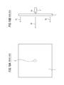
- JP-A-2009-130663 discloses a speaker device as shown in FIGS. 20A and 20B .
- a rectangle hole 7 a is formed in a flat-plate acoustic diaphragm 7 , an actuator 8 having a drive rod 8 a is fit in the rectangle hole 7 a , and thereby, vibration in the direction of the surface is applied to the acoustic diaphragm 7 .
- the sound wave is radiated at the homogeneous level in any part of the acoustic diaphragm 7 as shown in an arrow 9 a as is the case of the speaker device in FIGS. 19A and 19B .
- the thickness of the speaker may be made as thin as the thickness of the acoustic diaphragm 7 .
- the display panel part is made thin to about several millimeters or less, it is difficult to incorporate a typical speaker unit in the display panel part and maintain the thickness of the display panel part to about several millimeters or less.
- the speaker device of vibrating the acoustic diaphragm 1 in the direction perpendicular to the plate surface as shown in FIGS. 18A and 18B is incorporated in the display panel part, the direction of the length of the super-magnetostrictive actuator 2 is perpendicular to the panel surface, and it is also difficult to maintain the thickness of the display panel part to about several millimeters or less.
- a speaker system includes a display panel having a display screen, a structure having a plate part functioning as an acoustic diaphragm located outside of a perimeter of the display screen and being supported by the display panel, and an actuator attached to the structure so that a displacement direction of the actuator may be a direction of a plate surface of the plate part.
- the actuator is attached to each of locations at the left side and the right side of the display screen of the structure having a casing board shape so that a length direction of each actuator may be a direction of a plate surface of the structure.
- the thickness of the display panel part can be made sufficiently small.
- the thickness of the display panel part of the speaker system integrated with the display panel can be made sufficiently small.
- FIG. 1 shows a bezel of an example of a speaker system of the first embodiment seen from the rear side.
- FIG. 2 shows the bezel and a display panel of the example of the speaker system of the first embodiment seen from the rear side.
- FIG. 3 shows a sectional structure along a center axis of a laminated piezoelectric actuator of the example of the speaker system of the first embodiment.
- FIGS. 4A and 4B show an example of the laminated piezoelectric actuator.
- FIG. 5 shows differences in frequency characteristics depending on individual differences of the bezel.
- FIG. 6 shows the case where differences in frequency characteristics depending on individual differences of the bezel are small.
- FIGS. 7A to 7C show an example of a speaker system when a pre-load is applied to the laminated piezoelectric actuator.
- FIGS. 8A and 8B show another example of an actuator attachment configuration of the speaker system of the first embodiment.
- FIGS. 9A and 9B show another example of the actuator attachment configuration of the speaker system of the first embodiment.
- FIGS. 10A and 10B are diagrams for explanation of a difference between the first embodiment and the second embodiment.
- FIG. 11 shows an example of a speaker system of the second embodiment.
- FIG. 12 shows an example of a speaker system of the third embodiment.
- FIG. 13 shows another example of the speaker system of the third embodiment.
- FIG. 14 shows an example of a speaker system of the fourth embodiment.
- FIGS. 15A and 15B show examples of frequency characteristics of filters in FIG. 14 .
- FIG. 16 shows another example of the speaker system of the fourth embodiment.
- FIGS. 17A and 17B show an example of a speaker system of an embodiment of the invention.
- FIGS. 18A and 18B show a speaker device shown in JP-A-4-313999 and JP-A-2005-177688.
- FIGS. 19A and 19B show a speaker device shown in JP-A-2007-166027.
- FIGS. 20A and 20B show a speaker device shown in commonly-owned JP-A-2009-130663.
- FIGS. 1 to 9B [1. First Embodiment: FIGS. 1 to 9B ]
- FIGS. 1 to 6 Example of First Embodiment: FIGS. 1 to 6 )
- FIGS. 1 to 3 >
- FIGS. 1 , 2 , and 3 show an example of the speaker system of the first embodiment.
- FIG. 1 shows a bezel seen from the rear side
- FIG. 2 shows the bezel supporting a display panel seen from the rear side
- FIG. 3 shows a section of an actuator attachment part in FIGS. 1 and 2 .
- the upper side refers to the upper side of the display screen
- the lower side refers to the lower side of the display screen
- the left side refers to the left side of the display screen seen from the front side
- the right side refers to the right side of the display screen seen from the front side.
- a bezel 10 has a casing board shape (frame shape) with an upper side plate part 11 , a lower side plate part 12 , a left side plate part 13 , and a right side plate part 14 .
- the bezel 10 is made of a material with good acoustic characteristics to function as an acoustic diaphragm.
- a material with good acoustic characteristics for example, among metals, magnesium is preferable.
- a strip-shaped rubber piece 15 is attached to the rear side of the upper side plate part 11 , and ring-shaped rubber pieces 16 are attached to the rear side of the lower side plate part 12 , the left side plate part 13 , and the right side plate part 14 .
- laminated piezoelectric actuators 70 L and 70 R are attached to the rear side of the left side plate part 13 and the right side plate part 14 of the bezel 10 .
- receiving portions 21 and 22 projecting toward the rear side are provided on the left side plate part 13 , and the laminated piezoelectric actuator 70 L is attached between the receiving portion 21 and the receiving portion 22 so that its displacement direction (vibration direction) may be the vertical direction of the screen.
- the receiving portions 21 and 22 projecting toward the rear side are provided on the right side plate part 14 , and the laminated piezoelectric actuator 70 R is attached between the receiving portion 21 and the receiving portion 22 so that its displacement direction (vibration direction) may be the vertical direction of the screen.
- the receiving portions 21 and 22 are formed integrally with the bezel 10 , or formed separately from the bezel 10 and attached to the bezel 10 using screws or an adhesive.
- the laminated piezoelectric actuators 70 L and 70 R are attached to the bezel 10 via an adhesive between the receiving portions 21 and 22 , respectively, for example.
- the vibration of the laminated piezoelectric actuators 70 L and 70 R is transmitted to the bezel 10 via the receiving portions 21 and 22 , respectively, as longitudinal vibration along the surface. Thereby, sound wave is radiated in the front direction perpendicular to the surface of the bezel 10 .
- the receiving portions 21 and 22 are made of a hard material for efficient propagation of vibration.
- tape-like buffer members 31 are attached using double-faced tapes or the like to the rear side of the upper side plate part 11 , the lower side plate part 12 , the left side plate part 13 , and the right side plate part 14 .
- nonwoven fabric such as Himelon (product name) may be used.
- the display panel 40 is a flat display panel such as an organic EL display panel, and displays images on the display screen.
- a chassis 50 is attached to the rear side of the display panel 40 . Though omitted in the drawing, a circuit board etc. are attached to the chassis 50 .
- the display panel 40 to which the chassis 50 has been attached is inserted to the rear side of the bezel 10 such that display panel 40 is held between the rubber pieces 15 and 16 , and the display panel 40 is supported by the bezel 10 by screwing screws 51 from the outside of the chassis 50 into the screw holes 17 shown in FIG. 1 .
- the rubber pieces 15 and 16 slightly yield into elastic contact with the perimeter end surface of the display panel 40 , and thereby, variations in relative positions in the surface direction of the display screen between the bezel 10 and the display panel 40 are absorbed and breakage of the display panel 40 on impact is prevented.
- buffer members 31 intervene between the bezel 10 and the perimeter of the display panel 40 , and thereby, the acoustic characteristics are improved as described later.
- the rear cover 60 is put on the rear side of the bezel 10 as shown in FIG. 3 , and the rear cover 60 is attached to the bezel 10 by screwing the screws from the outside of the rear cover 60 into the screw hole portions 18 and 19 shown in FIG. 1 .
- buffer members 32 are attached to the receiving portions 21 and 22 as well and the buffer members 32 intervene between the receiving portions 21 and 22 and the rear cover 60 .
- FIGS. 4A and 4B show an example of a laminated piezoelectric actuator used as the laminated piezoelectric actuator 70 L or 70 R.
- FIG. 4A is a schematic perspective view and FIG. 4B is a schematic sectional view.
- external electrodes 72 and 73 are formed on opposed side surfaces of a piezoelectric ceramic thin plate laminate 71 .
- piezoelectric ceramic thin plate laminate 71 many piezoelectric ceramic thin plates are laminated with internal electrodes 74 and 75 alternately in between.
- the internal electrodes 74 are connected to the external electrode 72 and the internal electrodes 75 are connected to the external electrode 73 .
- the laminated piezoelectric actuators may have a width W of about 3.5 mm in the direction in which the external electrodes 72 and 73 are opposed and a depth D of about 2 mm.
- the laminated piezoelectric actuators are attached to the bezel 10 so that the direction of the width W may be in parallel to the display screen and the direction of the depth D may be perpendicular to the display screen.
- the thickness may be set to several millimeters or less.
- a magnetic bias is not necessary for the laminated piezoelectric actuator unlike the super-magnetostrictive actuator, and the simpler and smaller actuator can be formed.
- the laminated piezoelectric actuator generates a large stress and provides a high response speed like the super-magnetostrictive actuator.
- FIGS. 5 and 6 >
- the vibration of the laminated piezoelectric actuators 70 L and 70 R is transmitted to the bezel 10 as longitudinal vibration and sound wave is radiated in the front direction perpendicular to the surface of the bezel 10 .
- the buffer members 31 intervene between the bezel 10 and the perimeter of the display panel 40 , and thereby, variations in acoustic characteristics depending on individual differences of the bezel 10 are absorbed and the acoustic characteristics are improved as below.
- FIG. 5 shows differences in frequency characteristics of sound pressure level depending on individual differences of the bezel 10 when no buffer member 31 exists and the bezel 10 is in direct contact with the perimeter of the display panel 40 .
- Sample A, sample B, sample C, and sample D are four bezels manufactured from the same material (magnesium) by the same manufacturing method in the same size, and they are slightly different in warpage.
- the frequency characteristics of sound pressure level vary depending on individual differences of the bezel, and further, in sample A, significant reduction of the sound pressure level is recognized around 8 kHz.
- FIG. 6 shows the case where the buffer members 31 intervene between the bezel 10 and the perimeter of the display panel 40 as in the above described example.
- the laminated piezoelectric actuator is capacitive. Accordingly, when the laminated piezoelectric actuators 70 L and 70 R are attached to the bezel 10 as in the example in FIGS. 1 to 3 , the sound pressure level becomes higher as the frequency becomes higher in the high frequency range as shown in FIGS. 5 and 6 . This may be addressed as described below.
- the laminated piezoelectric actuators 70 L and 70 R can be driven using the same sound signal.
- the laminated piezoelectric actuators 70 L and 70 R may be driven using separate sound signals by driving the laminated piezoelectric actuator 70 L by a left-channel signal of a stereo sound signal and driving the laminated piezoelectric actuator 70 R by a right-channel signal of the stereo sound signal.
- the laminated piezoelectric actuators 70 L and 70 R may be driven using a middle-to-high-frequency component of the sound signal as described below.
- a sound image is localized at the outside of the left side and the outside of the right side of the display screen in view of auditory sensation.
- FIGS. 7A to 7C (1-2. Example of Pre-load Application: FIGS. 7A to 7C )
- the laminated piezoelectric actuators 70 L and 70 R are stretched.
- the piezoelectric element is mechanically weak to tension. Accordingly, it is desirable that pre-loads are applied to the laminated piezoelectric actuators 70 L and 70 R. When the pre-loads are applied to the laminated piezoelectric actuators 70 L and 70 R, the sound quality is also improved.
- the pre-loads are applied to the laminated piezoelectric actuators 70 L and 70 R using eccentric cam rings, circular disk cams or the like in the actuator attachment part.
- FIGS. 7A to 7C show an example thereof.
- FIGS. 7A , 7 B, 7 C show the left side plate part and the right side plate part of the bezel 10 seen from the rear side.
- a receiving portion 24 has a shape into which one end of the laminated piezoelectric actuator is inserted from above, and one end of the laminated piezoelectric actuator is inserted into the receiving portion 24 .
- an eccentric cam ring 23 is attached to a shaft 23 a of the bezel 10 in a location at the other end of the laminated piezoelectric actuator.
- the eccentric cam ring 23 may be fixed to the bezel 10 using an adhesive or the like so as not to rotate relative to the adjusted rotational position due to external vibration or impact.
- FIGS. 8A and 8B and 9 A and 9 B are identical to FIGS. 8A and 8B and 9 A and 9 B.
- the actuator attachment part of the bezel 10 may be formed as below.
- FIGS. 8A and 8B show an example of the part.
- FIG. 8A shows the left side plate part and the right side plate part of the bezel 10 seen from the rear side
- FIG. 8B is a sectional view thereof.
- grooves 25 are formed on the rear side of the left side plate part and the right side plate part of the bezel 10 and the laminated piezoelectric actuators are attached into the grooves 25 using an adhesive 26 .
- the adhesive 26 is desirably a hard material.
- FIGS. 9A and 9B show another example.
- FIG. 9A shows an actuator attachment plate onto which the laminated piezoelectric actuator is attached
- FIG. 9B is a side view with the section of the bezel part.
- an actuator attachment plate 27 in which holes 28 for screws are formed is prepared separately from the bezel 10 , and the laminated piezoelectric actuator is attached to the plate using an adhesive, double-faced tape, or the like.
- the actuator attachment plates 27 on which the laminated piezoelectric actuators have been attached are attached to the rear side of the left side plate part and the right side plate part of the bezel 10 using screws 29 .
- the laminated piezoelectric actuators are used as adapters, and thereby, the laminated piezoelectric actuators can be efficiently attached to the bezel 10 and productivity of speaker system is improved.
- FIGS. 10A and 10B and 11 [2. Second Embodiment: FIGS. 10A and 10B and 11 ]
- an angle ⁇ relative to an extension direction (horizontal direction of the screen) of the end surface 10 a of the bezel 10 in the displacement direction (vibration direction) of the laminated piezoelectric actuator shown by an arrow 79 is a right angle.
- the longitudinal wave propagating from the vibration application point Pa of the bezel 10 to the point Pr on the end surface 10 a is reflected at the point Pr in the displacement direction of the laminated piezoelectric actuator, and resonance occurs between the longitudinal wave propagating to the point Pr and the longitudinal wave reflected at the point Pr.
- the opposite end surface to the end surface 10 a is true with the opposite end surface to the end surface 10 a.
- the angle relative to an extension direction (horizontal direction of the screen) of the end surface 10 a of the bezel 10 in the displacement direction (vibration direction) of the laminated piezoelectric actuator shown by an arrow 79 is not a right angle but an angle between 0° and 90°.
- the longitudinal wave propagating from the vibration application point to the point on the end surface 10 a is mainly reflected at the point on the end surface 10 a in a direction different from the displacement direction of the laminated piezoelectric actuator, and resonance by the reflected wave is reduced.
- the opposite end surface to the end surface 10 a is the opposite end surface to the end surface 10 a.
- FIG. 11 shows an example of a speaker system of the second embodiment.
- FIG. 11 shows the speaker system seen from the front side and laminated piezoelectric actuators by broken lines.
- the laminated piezoelectric actuator 70 L is attached to the rear side of the left side plate part of the bezel 10 with the displacement direction at a tilt to some degree relative to the vertical direction of the screen, and the laminated piezoelectric actuator 70 R is attached to the rear side of the right side plate part of the bezel 10 symmetrically relative to the laminated piezoelectric actuator 70 L.
- FIGS. 12 and 13 [3. Third Embodiment: FIGS. 12 and 13 ]
- FIG. 12 shows an example of the speaker system of the third embodiment, and shows the speaker system seen from the front side like FIG. 11 .
- the laminated piezoelectric actuator 70 L is attached to the rear side at the center of the left side plate part of the bezel 10 in the vertical direction of the screen
- the laminated piezoelectric actuator 70 R is attached to the rear side at the center of the right side plate part of the bezel 10 in the vertical direction of the screen.
- a laminated piezoelectric actuator Cu is attached to the rear side at the center of the upper side plate part of the bezel 10 in the vertical direction of the screen
- a laminated piezoelectric actuator Cd is attached to the rear side at the center of the lower side plate part of the bezel 10 in the vertical direction of the screen.
- a sound image can be moved and localized in conjunction with the movement of an object or the like displayed on a display screen 41 by controlling the levels and phases of the sound signals supplied to the individual laminated piezoelectric actuators.
- the level of the signal supplied to the laminated piezoelectric actuator 70 L and the level of the signal supplied to the laminated piezoelectric actuator 70 R are made equal, and the level of the signal supplied to the laminated piezoelectric actuator Cu is made higher than the level of the signal supplied to the laminated piezoelectric actuator Cd.
- the sound image can be localized in an upper location in the vertical direction at the center in the horizontal direction of the display screen 41 .
- FIG. 13 shows another example of the speaker system of the third embodiment, and shows the speaker system seen from the front side like FIG. 12 .
- a laminated piezoelectric actuator 70 Lu is attached to the rear side in the upper left corner part of the bezel 10 with its displacement direction tilted at 45° relative to the screen horizontal direction and the screen vertical direction, and a laminated piezoelectric actuator 70 Ld is attached to the rear side in the lower left corner part of the bezel 10 vertically symmetric relative to the laminated piezoelectric actuator 70 Lu.
- laminated piezoelectric actuators 70 Ru and 70 Rd are attached to the rear side in the upper right corner part and the lower right corner part of the bezel 10 horizontally symmetric relative to the laminated piezoelectric actuators 70 Lu and 70 Ld, respectively.
- a sound image can be moved and localized in conjunction with the movement of an object or the like displayed on the display screen 41 by controlling the levels and phases of the sound signals supplied to the individual laminated piezoelectric actuators.
- the levels of the signals supplied to the laminated piezoelectric actuators 70 Lu and 70 Ru are made higher and the levels of the signals supplied to the laminated piezoelectric actuators 70 Ld and 70 Rd are made lower.
- the sound image can be localized in an upper location in the vertical direction at the center in the horizontal direction of the display screen 41 .
- angles relative to the extension directions of the end surface 10 a of the bezel 10 of the in the displacement directions (vibration directions) of the respective laminated piezoelectric actuators are 45°, and therefore, as an example of the above described embodiment, resonance due to reflected wave is reduced.
- FIGS. 14 to 16 [4. Fourth Embodiment: FIGS. 14 to 16 ]
- a speaker system of the fourth embodiment of the invention not only the actuators are attached to a display panel part as described above, but also a typical speaker unit can be provided at the same time.
- FIG. 14 shows an example of the speaker system of the fourth embodiment.
- a display panel part 90 is mounted on a pedestal box 110 using a columnar support 100 .
- the laminated piezoelectric actuators 70 L and 70 R are attached to the rear side of the left side plate part and the right side plate part of the bezel 10 .
- Typical speaker units 120 L and 120 R respectively having voice coils and cones are attached to the right and left locations seen from the front side of the pedestal box 110 with the speaker front surfaces directed upward.
- the vibration speaker formed by the laminated piezoelectric actuators 70 L and 70 R and the bezel 10 functions as a tweeter and the typical speaker units 120 L and 120 R functions as woofers.
- the tweeter band shows a frequency response peculiar to the configuration of the vibration speaker, and the frequency characteristic is corrected by a DSP (Digital Signal Processor) according to need.
- DSP Digital Signal Processor
- a left-channel signal SL and a right-channel signal SR of the stereo sound signal that have been digitally processed for frequency correction and converted into analog signals are obtained from a DSP 130 .
- the left-channel signal SL is amplified by a sound amplifier circuit 141 , and then, separated into a middle-to-high-frequency component and a low-frequency component by an analog HPF (high-pass filter) 151 and an analog LPF (low-pass filter) 152 .
- HPF high-pass filter
- LPF low-pass filter
- the signal of the middle-to-high-frequency component of the left channel from the analog HPF 151 is supplied to the laminated piezoelectric actuator 70 L, and the signal of the low-frequency component of the left channel from the analog LPF 152 is supplied to the speaker unit 120 L.
- the right-channel signal SR is amplified by a sound amplifier circuit 145 , and then, separated into a middle-to-high-frequency component and a low-frequency component by an analog HPF (high-pass filter) 155 and an analog LPF (low-pass filter) 156 .
- HPF high-pass filter
- LPF low-pass filter
- the signal of the middle-to-high-frequency component of the right channel from the analog HPF 155 is supplied to the laminated piezoelectric actuator 70 R, and the signal of the low-frequency component of the right channel from the analog LPF 156 is supplied to the speaker unit 120 R.
- the laminated piezoelectric actuators 70 L and 70 R are driven by voltages and the speaker units 120 L and 120 R are driven by currents. Accordingly, the entire speaker system is designed by selecting DCRs (direct-current resistors) of the speaker units 120 L and 120 R so that sound pressure may be matched between the laminated piezoelectric actuators 70 L and 70 R side and the speaker units 120 L and 120 R side and otherwise.
- DCRs direct-current resistors
- the frequency characteristics of the analog LPFs 152 and 156 are flat in the low frequency range as shown in FIG. 15A .
- the frequency characteristics of the analog HPFs 151 and 155 are, when the sound pressure level becomes higher as the frequency becomes higher in the high frequency range as shown in FIGS. 5 and 6 , characteristics that are not flat in the middle-to-high frequency range as shown by a broken line in FIG. 15B and the pass level becomes lower as the frequency becomes higher in the middle-to-high frequency range as shown by a solid line in FIG. 15B .
- processing of reducing the level in the high frequency range may be performed not only by the analog HPFs 151 and 155 but by the DSP 130 at the upstream.
- FIG. 16 shows another example of the speaker system of the fourth embodiment. This example is the same as the example of FIG. 14 except the method of driving speakers.
- the signal of the middle-to-high-frequency component of the left channel, the signal of the low-frequency component of the left channel, the signal of the middle-to-high-frequency component of the right channel, and the signal of the low-frequency component of the right channel are separately processed.
- the signal of the middle-to-high-frequency component of the left channel is digitally processed in the DSP 130 , and then, converted into an analog signal SLH by the DSP 130 , amplified by a sound amplifier circuit 161 , and supplied to the laminated piezoelectric actuator 70 L.
- the signal of the low-frequency component of the left channel is digitally processed in the DSP 130 , and then, converted into an analog signal SLL by the DSP 130 , amplified by a sound amplifier circuit 162 , and supplied to the speaker unit 120 L.
- the signal of the middle-to-high-frequency component of the right channel is digitally processed in the DSP 130 , and then, converted into an analog signal SRH by the DSP 130 , amplified by a sound amplifier circuit 165 , and supplied to the laminated piezoelectric actuator 70 R.
- the signal of the low-frequency component of the right channel is digitally processed in the DSP 130 , and then, converted into an analog signal SRL by the DSP 130 , amplified by a sound amplifier circuit 166 , and supplied to the speaker unit 120 R.
- the processing of reducing the level in the high frequency range as shown in FIG. 15B is performed in the DSP 130 .
- the sound image signal localization effect on the display screen due to the Haas effect can be improved by delaying the signals of the low-frequency components with a time difference of about several milliseconds to several tens of milliseconds between the signals supplied to the laminated piezoelectric actuators 70 L and 70 R and the signals supplied to the speaker units 120 L and 120 R.
- FIGS. 17A and 17B [5. Another Embodiment or Example: FIGS. 17A and 17B ]
- FIGS. 17A and 17B (5-1. Regarding Structure: FIGS. 17A and 17B )
- the structure functioning as an acoustic diaphragm is the bezel 10 having a casing board shape (frame shape), however, the structure may not necessarily have the casing board shape.
- FIGS. 17A and 17B show an example in which the structure does not have the casing board shape, but has a rectangular flat board shape.
- FIG. 17A shows a speaker system seen from the front side
- FIG. 17B shows a cross section along a line Y in FIG. 17A .
- a transparent rectangular flat board of an acryl board is provided as a front panel 80 , and the display panel 40 and the laminated piezoelectric actuators 70 L and 70 R are attached to the rear side thereof.
- the laminated piezoelectric actuators 70 L and 70 R are attached to the front panel 80 at the left side and the right side of the display screen 41 .
- the part in front of the display screen 41 of the front panel 80 is transparent, however, if the surrounding parts on the top, bottom, right, and left thereof are transparent, the appearance is poor because the laminated piezoelectric actuators 70 L and 70 R are seen from the front side.
- a film 81 for making the parts opaque is formed on the parts surrounding the display screen 41 on the front surface of the front panel 80 .
- the laminated piezoelectric actuators are used as actuators, however, super-magnetostrictive actuators, static actuators, or the like may be used as actuators.
- rectangular holes may be formed in the bezel and actuators may be fit in the rectangular holes, and vibration in the surface direction is applied to the bezel.
Landscapes
- Engineering & Computer Science (AREA)
- Physics & Mathematics (AREA)
- Theoretical Computer Science (AREA)
- General Engineering & Computer Science (AREA)
- General Physics & Mathematics (AREA)
- Human Computer Interaction (AREA)
- Computer Hardware Design (AREA)
- Multimedia (AREA)
- Acoustics & Sound (AREA)
- Signal Processing (AREA)
- Piezo-Electric Transducers For Audible Bands (AREA)
- Details Of Audible-Bandwidth Transducers (AREA)
- Diaphragms For Electromechanical Transducers (AREA)
- Circuit For Audible Band Transducer (AREA)
- Audible-Bandwidth Dynamoelectric Transducers Other Than Pickups (AREA)
Abstract
Description
Claims (17)
Applications Claiming Priority (4)
| Application Number | Priority Date | Filing Date | Title |
|---|---|---|---|
| JP2008-230391 | 2008-09-09 | ||
| JP2008230391 | 2008-09-09 | ||
| JP2008-323420 | 2008-12-19 | ||
| JP2008323420A JP4655243B2 (en) | 2008-09-09 | 2008-12-19 | Speaker system and speaker driving method |
Publications (2)
| Publication Number | Publication Date |
|---|---|
| US20100067726A1 US20100067726A1 (en) | 2010-03-18 |
| US9173030B2 true US9173030B2 (en) | 2015-10-27 |
Family
ID=41567272
Family Applications (1)
| Application Number | Title | Priority Date | Filing Date |
|---|---|---|---|
| US12/556,017 Expired - Fee Related US9173030B2 (en) | 2008-09-09 | 2009-09-09 | Speaker system and speaker driving method |
Country Status (5)
| Country | Link |
|---|---|
| US (1) | US9173030B2 (en) |
| EP (1) | EP2164279B1 (en) |
| JP (1) | JP4655243B2 (en) |
| CN (1) | CN101674505A (en) |
| TW (1) | TW201016038A (en) |
Cited By (2)
| Publication number | Priority date | Publication date | Assignee | Title |
|---|---|---|---|---|
| US20190215614A1 (en) * | 2018-01-09 | 2019-07-11 | Cirrus Logic International Semiconductor Ltd. | Multiple audio transducers driving a display to establish localized quiet zones |
| US20230283960A1 (en) * | 2020-08-03 | 2023-09-07 | Spt Co., Ltd. | Vibration module for piezoelectric speaker and panel speaker |
Families Citing this family (47)
| Publication number | Priority date | Publication date | Assignee | Title |
|---|---|---|---|---|
| TWM381090U (en) * | 2009-11-12 | 2010-05-21 | Chunghwa Picture Tubes Ltd | Display module |
| US10645834B2 (en) | 2010-08-23 | 2020-05-05 | Nokia Technologies Oy | Apparatus and method for providing haptic and audio feedback in a touch sensitive user interface |
| KR20120080882A (en) * | 2011-01-10 | 2012-07-18 | 삼성전자주식회사 | Acoustic transducer and method of driving the same |
| KR101793691B1 (en) * | 2011-03-09 | 2017-11-03 | 삼성전자주식회사 | Apparatus for outputting audio signal |
| US9148716B2 (en) * | 2012-01-12 | 2015-09-29 | Aac Acoustic Technologies (Shenzhen) Co., Ltd. | Vibration speaker |
| EP2822297B1 (en) * | 2012-02-28 | 2020-01-08 | Kyocera Corporation | Piezoelectric vibration element, piezoelectric vibration apparatus, and mobile terminal |
| GB2504691B (en) * | 2012-08-06 | 2015-01-28 | Jaguar Land Rover Ltd | Audio apparatus and method |
| CN104012115B (en) * | 2012-09-20 | 2018-02-16 | 京瓷株式会社 | Sound producer, flexible piezoelectric sound-generating devices and electronic equipment |
| KR101383702B1 (en) | 2012-12-12 | 2014-04-09 | 삼성디스플레이 주식회사 | Display unit |
| US9207750B2 (en) | 2012-12-14 | 2015-12-08 | Intel Corporation | Apparatus and method for reducing leakage power of a circuit |
| IL225374A0 (en) * | 2013-03-21 | 2013-07-31 | Noveto Systems Ltd | Transducer system |
| KR102062722B1 (en) * | 2013-03-25 | 2020-01-07 | 삼성디스플레이 주식회사 | Display apparatus, mobile device using the same and method for manufacturing the display apparatus |
| CN105191349B (en) * | 2013-05-15 | 2019-01-08 | 索尼公司 | Sound output device, method of outputting acoustic sound and image display device |
| US9976713B2 (en) * | 2013-07-05 | 2018-05-22 | Qualcomm Incorporated | Apparatus and method for providing a frequency response for audio signals |
| CN104282082A (en) * | 2013-07-11 | 2015-01-14 | 鸿富锦精密工业(武汉)有限公司 | Fixing device for display screen of vending machine |
| TW201508577A (en) * | 2013-08-28 | 2015-03-01 | Wintek Corp | Touch device capable of generating sound |
| CN104469567A (en) * | 2013-09-25 | 2015-03-25 | 鸿富锦精密工业(深圳)有限公司 | Loudspeaker and displayer |
| US10038947B2 (en) * | 2013-10-24 | 2018-07-31 | Samsung Electronics Co., Ltd. | Method and apparatus for outputting sound through speaker |
| KR102077236B1 (en) * | 2013-10-24 | 2020-02-13 | 삼성전자주식회사 | Method and apparatus for outputting sound through teum speaker |
| KR102205868B1 (en) * | 2014-07-14 | 2021-01-22 | 삼성디스플레이 주식회사 | Bidirectional display device |
| CN105578357A (en) * | 2014-10-07 | 2016-05-11 | 鸿富锦精密工业(深圳)有限公司 | Electronic device with speaker |
| EP4280625A3 (en) * | 2015-08-20 | 2024-02-07 | The University of Rochester | Systems and methods for controlling plate loudspeakers using modal crossover networks |
| US9553960B1 (en) * | 2015-09-04 | 2017-01-24 | Intel Corporation | Loudspeaker with laminate panel for mobile computing platforms |
| CN108293166B (en) * | 2015-11-25 | 2020-10-02 | 罗切斯特大学 | Time and space control system and method for panel vibration and virtual source generation method |
| US10123128B2 (en) * | 2016-09-07 | 2018-11-06 | Microsoft Technology Licensing, Llc | Speaker arrangement |
| JP6236503B1 (en) * | 2016-09-16 | 2017-11-22 | シャープ株式会社 | Acoustic device, display device, and television receiver |
| KR102308042B1 (en) * | 2017-07-28 | 2021-09-30 | 엘지디스플레이 주식회사 | Display apparatus |
| CN107592592A (en) * | 2017-07-28 | 2018-01-16 | 捷开通讯(深圳)有限公司 | Display panel, mobile terminal and screen sounding control method |
| KR102420554B1 (en) * | 2017-08-10 | 2022-07-14 | 삼성디스플레이 주식회사 | Display panel, bracket and display device comprising the same |
| KR102343283B1 (en) * | 2017-08-21 | 2021-12-27 | 삼성디스플레이 주식회사 | Display apparatus |
| KR102430582B1 (en) * | 2017-11-28 | 2022-08-08 | 엘지디스플레이 주식회사 | Display Device |
| WO2019131041A1 (en) * | 2017-12-28 | 2019-07-04 | ソニー株式会社 | Display apparatus |
| WO2019130972A1 (en) | 2017-12-28 | 2019-07-04 | ソニー株式会社 | Display apparatus and signal generating apparatus |
| KR102594577B1 (en) | 2018-08-22 | 2023-10-25 | 엘지디스플레이 주식회사 | Display apparatus |
| KR102530589B1 (en) * | 2018-09-20 | 2023-05-08 | 엘지디스플레이 주식회사 | Display apparatus and computing apparatus using the same |
| TWI662522B (en) * | 2018-11-21 | 2019-06-11 | 友達光電股份有限公司 | Display apparatus |
| TWI804048B (en) * | 2019-02-28 | 2023-06-01 | 南韓商樂金顯示科技股份有限公司 | Display apparatus |
| KR102662671B1 (en) * | 2019-03-29 | 2024-04-30 | 엘지디스플레이 주식회사 | Display apparatus |
| EP3958585A4 (en) | 2019-04-16 | 2022-06-08 | Sony Group Corporation | Display device, control method, and program |
| KR102689721B1 (en) * | 2019-07-22 | 2024-07-29 | 엘지디스플레이 주식회사 | Display apparatus and vehicle comprising the same |
| CN110557705B (en) * | 2019-08-26 | 2021-09-10 | Oppo广东移动通信有限公司 | Electronic device |
| CN110572758B (en) * | 2019-09-16 | 2021-04-13 | Oppo广东移动通信有限公司 | Polarizers, Displays, Electronic Equipment |
| WO2021117575A1 (en) | 2019-12-10 | 2021-06-17 | ソニーグループ株式会社 | Voice output device and vibration mechanism |
| US11800293B2 (en) * | 2020-06-15 | 2023-10-24 | Lg Display Co., Ltd. | Sound apparatus |
| US12474877B2 (en) | 2020-10-07 | 2025-11-18 | Sony Group Corporation | Output apparatus |
| KR20230160805A (en) * | 2021-03-31 | 2023-11-24 | 소니그룹주식회사 | Display devices, output methods and display modules |
| WO2025225421A1 (en) * | 2024-04-22 | 2025-10-30 | ソニーグループ株式会社 | Audio output device |
Citations (29)
| Publication number | Priority date | Publication date | Assignee | Title |
|---|---|---|---|---|
| JPH04313999A (en) | 1991-01-18 | 1992-11-05 | Onkyo Corp | Speaker using giant magnetostrictive vibrator |
| JPH05111096A (en) | 1991-10-15 | 1993-04-30 | Mitsubishi Heavy Ind Ltd | Mechanism for expanding fine displacement |
| US5342989A (en) * | 1993-05-14 | 1994-08-30 | Bbe Sound, Inc. | Planar wave transducer assembly |
| JP2001189978A (en) | 1999-10-18 | 2001-07-10 | Authentic Ltd | Panel-type speaker |
| JP2003244784A (en) | 2002-02-15 | 2003-08-29 | Sharp Corp | Card-type device and electronic device provided with the same |
| US20050047616A1 (en) * | 2003-09-03 | 2005-03-03 | Noel Lee | Flat panel monitor frame with integral speakers |
| JP2005177688A (en) | 2003-12-22 | 2005-07-07 | Nikkeikin Aluminium Core Technology Co Ltd | Supermagnetostriction actuator |
| JP2005197868A (en) | 2004-01-05 | 2005-07-21 | Nec Access Technica Ltd | Panel type speaker, display apparatus, and foldable information processing apparatus |
| US20050185801A1 (en) * | 2004-02-24 | 2005-08-25 | Mccarty William A. | System and method for mounting of audio-visual components |
| US20060023898A1 (en) | 2002-06-24 | 2006-02-02 | Shelley Katz | Apparatus and method for producing sound |
| WO2006038176A1 (en) | 2004-10-08 | 2006-04-13 | Koninklijke Philips Electronics N.V. | Display device comprising a panel acoustic transducer, and transparent panel acoustic transducer |
| JP2006513656A (en) | 2003-01-22 | 2006-04-20 | カッツ,シェレィ | Apparatus and method for generating sound |
| US20060232564A1 (en) * | 2005-02-04 | 2006-10-19 | Nec Infrontia Corporation | Electronic apparatus |
| WO2006114985A1 (en) | 2005-04-22 | 2006-11-02 | Sharp Kabushiki Kaisha | Card type device and method for manufacturing same |
| US20070080951A1 (en) * | 2002-08-29 | 2007-04-12 | Sony Corporation | Input device and electronic device using the input device |
| JP2007104602A (en) | 2005-10-07 | 2007-04-19 | Sony Corp | Image display device and audio output method |
| US20070115619A1 (en) * | 2005-11-04 | 2007-05-24 | Innolux Display Corp. | Flat panel display subassembly having speaker secured by integrated securing structure |
| JP2007166027A (en) | 2005-12-09 | 2007-06-28 | Sony Corp | Speaker device and audio output method |
| US20070177746A1 (en) * | 2003-07-02 | 2007-08-02 | Kazuhiro Kobayashi | Panel type speaker |
| JP2007208948A (en) | 2006-01-31 | 2007-08-16 | Taiyo Yuden Co Ltd | Portable electrical apparatus and display protection panel |
| JP2007214917A (en) | 2006-02-09 | 2007-08-23 | Sony Corp | Speaker device and audio output method |
| US20070209173A1 (en) * | 2003-12-24 | 2007-09-13 | Kyocera Corporation | Laminated Piezoelectric Device |
| US20070223747A1 (en) * | 2006-03-24 | 2007-09-27 | Victor Company Of Japan, Limited | Narrow speaker unit and image display apparatus having the narrow speaker |
| JP2007267302A (en) | 2006-03-30 | 2007-10-11 | Nec Access Technica Ltd | Structure of displaying speaker and display coincident with sound source and image using the speaker |
| JP2008177980A (en) | 2007-01-22 | 2008-07-31 | Sony Corp | Speaker device |
| US20080285778A1 (en) * | 2005-08-02 | 2008-11-20 | Teijin Fibers Limited | Screen-Integrated Speaker |
| WO2009017280A1 (en) | 2007-07-30 | 2009-02-05 | Lg Electronics Inc. | Display device and speaker system for the display device |
| US20090034759A1 (en) * | 2007-01-02 | 2009-02-05 | Ko Young In | Display device and speaker system for the display device |
| US7639826B1 (en) * | 2004-01-08 | 2009-12-29 | New Transducers Limited | Bending wave panel loudspeaker |
Family Cites Families (1)
| Publication number | Priority date | Publication date | Assignee | Title |
|---|---|---|---|---|
| JP4524700B2 (en) | 2007-11-26 | 2010-08-18 | ソニー株式会社 | Speaker device and speaker driving method |
-
2008
- 2008-12-19 JP JP2008323420A patent/JP4655243B2/en not_active Expired - Fee Related
-
2009
- 2009-08-21 EP EP09252036.0A patent/EP2164279B1/en not_active Not-in-force
- 2009-08-21 CN CN200910168094A patent/CN101674505A/en active Pending
- 2009-08-26 TW TW098128680A patent/TW201016038A/en unknown
- 2009-09-09 US US12/556,017 patent/US9173030B2/en not_active Expired - Fee Related
Patent Citations (29)
| Publication number | Priority date | Publication date | Assignee | Title |
|---|---|---|---|---|
| JPH04313999A (en) | 1991-01-18 | 1992-11-05 | Onkyo Corp | Speaker using giant magnetostrictive vibrator |
| JPH05111096A (en) | 1991-10-15 | 1993-04-30 | Mitsubishi Heavy Ind Ltd | Mechanism for expanding fine displacement |
| US5342989A (en) * | 1993-05-14 | 1994-08-30 | Bbe Sound, Inc. | Planar wave transducer assembly |
| JP2001189978A (en) | 1999-10-18 | 2001-07-10 | Authentic Ltd | Panel-type speaker |
| JP2003244784A (en) | 2002-02-15 | 2003-08-29 | Sharp Corp | Card-type device and electronic device provided with the same |
| US20060023898A1 (en) | 2002-06-24 | 2006-02-02 | Shelley Katz | Apparatus and method for producing sound |
| US20070080951A1 (en) * | 2002-08-29 | 2007-04-12 | Sony Corporation | Input device and electronic device using the input device |
| JP2006513656A (en) | 2003-01-22 | 2006-04-20 | カッツ,シェレィ | Apparatus and method for generating sound |
| US20070177746A1 (en) * | 2003-07-02 | 2007-08-02 | Kazuhiro Kobayashi | Panel type speaker |
| US20050047616A1 (en) * | 2003-09-03 | 2005-03-03 | Noel Lee | Flat panel monitor frame with integral speakers |
| JP2005177688A (en) | 2003-12-22 | 2005-07-07 | Nikkeikin Aluminium Core Technology Co Ltd | Supermagnetostriction actuator |
| US20070209173A1 (en) * | 2003-12-24 | 2007-09-13 | Kyocera Corporation | Laminated Piezoelectric Device |
| JP2005197868A (en) | 2004-01-05 | 2005-07-21 | Nec Access Technica Ltd | Panel type speaker, display apparatus, and foldable information processing apparatus |
| US7639826B1 (en) * | 2004-01-08 | 2009-12-29 | New Transducers Limited | Bending wave panel loudspeaker |
| US20050185801A1 (en) * | 2004-02-24 | 2005-08-25 | Mccarty William A. | System and method for mounting of audio-visual components |
| WO2006038176A1 (en) | 2004-10-08 | 2006-04-13 | Koninklijke Philips Electronics N.V. | Display device comprising a panel acoustic transducer, and transparent panel acoustic transducer |
| US20060232564A1 (en) * | 2005-02-04 | 2006-10-19 | Nec Infrontia Corporation | Electronic apparatus |
| WO2006114985A1 (en) | 2005-04-22 | 2006-11-02 | Sharp Kabushiki Kaisha | Card type device and method for manufacturing same |
| US20080285778A1 (en) * | 2005-08-02 | 2008-11-20 | Teijin Fibers Limited | Screen-Integrated Speaker |
| JP2007104602A (en) | 2005-10-07 | 2007-04-19 | Sony Corp | Image display device and audio output method |
| US20070115619A1 (en) * | 2005-11-04 | 2007-05-24 | Innolux Display Corp. | Flat panel display subassembly having speaker secured by integrated securing structure |
| JP2007166027A (en) | 2005-12-09 | 2007-06-28 | Sony Corp | Speaker device and audio output method |
| JP2007208948A (en) | 2006-01-31 | 2007-08-16 | Taiyo Yuden Co Ltd | Portable electrical apparatus and display protection panel |
| JP2007214917A (en) | 2006-02-09 | 2007-08-23 | Sony Corp | Speaker device and audio output method |
| US20070223747A1 (en) * | 2006-03-24 | 2007-09-27 | Victor Company Of Japan, Limited | Narrow speaker unit and image display apparatus having the narrow speaker |
| JP2007267302A (en) | 2006-03-30 | 2007-10-11 | Nec Access Technica Ltd | Structure of displaying speaker and display coincident with sound source and image using the speaker |
| US20090034759A1 (en) * | 2007-01-02 | 2009-02-05 | Ko Young In | Display device and speaker system for the display device |
| JP2008177980A (en) | 2007-01-22 | 2008-07-31 | Sony Corp | Speaker device |
| WO2009017280A1 (en) | 2007-07-30 | 2009-02-05 | Lg Electronics Inc. | Display device and speaker system for the display device |
Cited By (4)
| Publication number | Priority date | Publication date | Assignee | Title |
|---|---|---|---|---|
| US20190215614A1 (en) * | 2018-01-09 | 2019-07-11 | Cirrus Logic International Semiconductor Ltd. | Multiple audio transducers driving a display to establish localized quiet zones |
| US11051112B2 (en) * | 2018-01-09 | 2021-06-29 | Cirrus Logic, Inc. | Multiple audio transducers driving a display to establish localized quiet zones |
| US20230283960A1 (en) * | 2020-08-03 | 2023-09-07 | Spt Co., Ltd. | Vibration module for piezoelectric speaker and panel speaker |
| US12207051B2 (en) * | 2020-08-03 | 2025-01-21 | Spt Co., Ltd. | Vibration module for piezoelectric speaker and panel speaker |
Also Published As
| Publication number | Publication date |
|---|---|
| EP2164279A1 (en) | 2010-03-17 |
| JP4655243B2 (en) | 2011-03-23 |
| CN101674505A (en) | 2010-03-17 |
| US20100067726A1 (en) | 2010-03-18 |
| EP2164279B1 (en) | 2016-10-05 |
| JP2010093769A (en) | 2010-04-22 |
| TW201016038A (en) | 2010-04-16 |
Similar Documents
| Publication | Publication Date | Title |
|---|---|---|
| US9173030B2 (en) | Speaker system and speaker driving method | |
| KR101919454B1 (en) | Display apparatus and computing apparatus | |
| JP6489291B2 (en) | Flat panel speaker and display device | |
| KR101817103B1 (en) | Display device for generating sound by panel vibration type | |
| KR102356794B1 (en) | Display apparatus | |
| CN102405652B (en) | Piezoelectric acoustic transducer | |
| US12015906B2 (en) | Sound generating device, display apparatus including the same, and automotive apparatus including the sound generating device | |
| US9942640B2 (en) | Sound output apparatus, sound output method and image display apparatus | |
| EP1800514B1 (en) | Display device comprising a panel acoustic transducer, and transparent panel acoustic transducer | |
| EP2360938B1 (en) | Sound plate and electronic device employing the same | |
| US20070206822A1 (en) | Loudspeakers | |
| CN108028990B (en) | Sound reproduction display | |
| WO2013121715A1 (en) | Speaker | |
| US11647317B2 (en) | Display apparatus | |
| JP2006129053A (en) | Flat-panel speaker | |
| US7769191B2 (en) | Flat panel audio output apparatus and video/audio output apparatus | |
| KR20190013680A (en) | Display apparatus and computing apparatus | |
| US10129640B2 (en) | Suppressing a modal frequency of a loudspeaker | |
| KR102458174B1 (en) | Electronic apparatus | |
| KR101890761B1 (en) | Display Panel Speaker | |
| US20230354712A1 (en) | Audio Device And Driving Method Thereof, And Display Device | |
| US8422720B2 (en) | Speaker arrangement | |
| CN217088035U (en) | Display device | |
| EP3926979A1 (en) | Loudspeaker apparatus |
Legal Events
| Date | Code | Title | Description |
|---|---|---|---|
| AS | Assignment |
Owner name: SONY CORPORAATION, JAPAN Free format text: CORRECTIVE ASSIGNMENT TO CORRECT THE REMOVE THE INCORRECT SERIAL NO. 12/566017 PREVIOUSLY RECORDED ON REEL 023520 FRAME 0879. ASSIGNOR(S) HEREBY CONFIRMS THE ASSIGNMENT OF ASSIGNOR(S) INTEREST;ASSIGNORS:SUZUKI, NOBUKAZU;OHASHI, YOSHIO;INATANI, AKIHISA;AND OTHERS;SIGNING DATES FROM 20091030 TO 20091110;REEL/FRAME:025006/0098 Owner name: SONY CORPORATION, JAPAN Free format text: CORRECTIVE ASSIGNMENT TO CORRECT THE REMOVE THE INCORRECT SERIAL NO. 12/566017 PREVIOUSLY RECORDED ON REEL 023520 FRAME 0879. ASSIGNOR(S) HEREBY CONFIRMS THE ASSIGNMENT OF ASSIGNOR(S) INTEREST;ASSIGNORS:SUZUKI, NOBUKAZU;OHASHI, YOSHIO;INATANI, AKIHISA;AND OTHERS;SIGNING DATES FROM 20091030 TO 20091110;REEL/FRAME:025006/0098 |
|
| FEPP | Fee payment procedure |
Free format text: PAYOR NUMBER ASSIGNED (ORIGINAL EVENT CODE: ASPN); ENTITY STATUS OF PATENT OWNER: LARGE ENTITY |
|
| ZAAA | Notice of allowance and fees due |
Free format text: ORIGINAL CODE: NOA |
|
| ZAAB | Notice of allowance mailed |
Free format text: ORIGINAL CODE: MN/=. |
|
| STCF | Information on status: patent grant |
Free format text: PATENTED CASE |
|
| MAFP | Maintenance fee payment |
Free format text: PAYMENT OF MAINTENANCE FEE, 4TH YEAR, LARGE ENTITY (ORIGINAL EVENT CODE: M1551); ENTITY STATUS OF PATENT OWNER: LARGE ENTITY Year of fee payment: 4 |
|
| FEPP | Fee payment procedure |
Free format text: MAINTENANCE FEE REMINDER MAILED (ORIGINAL EVENT CODE: REM.); ENTITY STATUS OF PATENT OWNER: LARGE ENTITY |
|
| LAPS | Lapse for failure to pay maintenance fees |
Free format text: PATENT EXPIRED FOR FAILURE TO PAY MAINTENANCE FEES (ORIGINAL EVENT CODE: EXP.); ENTITY STATUS OF PATENT OWNER: LARGE ENTITY |
|
| STCH | Information on status: patent discontinuation |
Free format text: PATENT EXPIRED DUE TO NONPAYMENT OF MAINTENANCE FEES UNDER 37 CFR 1.362 |
|
| FP | Lapsed due to failure to pay maintenance fee |
Effective date: 20231027 |