US9171582B2 - Rugged hard drive - Google Patents
Rugged hard drive Download PDFInfo
- Publication number
- US9171582B2 US9171582B2 US13/953,365 US201313953365A US9171582B2 US 9171582 B2 US9171582 B2 US 9171582B2 US 201313953365 A US201313953365 A US 201313953365A US 9171582 B2 US9171582 B2 US 9171582B2
- Authority
- US
- United States
- Prior art keywords
- sleeve
- hard drive
- cavity
- distance
- dimensions
- Prior art date
- Legal status (The legal status is an assumption and is not a legal conclusion. Google has not performed a legal analysis and makes no representation as to the accuracy of the status listed.)
- Active, expires
Links
Images


Classifications
-
- G—PHYSICS
- G11—INFORMATION STORAGE
- G11B—INFORMATION STORAGE BASED ON RELATIVE MOVEMENT BETWEEN RECORD CARRIER AND TRANSDUCER
- G11B33/00—Constructional parts, details or accessories not provided for in the other groups of this subclass
- G11B33/02—Cabinets; Cases; Stands; Disposition of apparatus therein or thereon
- G11B33/08—Insulation or absorption of undesired vibrations or sounds
-
- G—PHYSICS
- G06—COMPUTING OR CALCULATING; COUNTING
- G06F—ELECTRIC DIGITAL DATA PROCESSING
- G06F1/00—Details not covered by groups G06F3/00 - G06F13/00 and G06F21/00
- G06F1/16—Constructional details or arrangements
- G06F1/1613—Constructional details or arrangements for portable computers
- G06F1/1633—Constructional details or arrangements of portable computers not specific to the type of enclosures covered by groups G06F1/1615 - G06F1/1626
- G06F1/1656—Details related to functional adaptations of the enclosure, e.g. to provide protection against EMI, shock, water, or to host detachable peripherals like a mouse or removable expansions units like PCMCIA cards, or to provide access to internal components for maintenance or to removable storage supports like CDs or DVDs, or to mechanically mount accessories
- G06F1/1658—Details related to functional adaptations of the enclosure, e.g. to provide protection against EMI, shock, water, or to host detachable peripherals like a mouse or removable expansions units like PCMCIA cards, or to provide access to internal components for maintenance or to removable storage supports like CDs or DVDs, or to mechanically mount accessories related to the mounting of internal components, e.g. disc drive or any other functional module
-
- G—PHYSICS
- G06—COMPUTING OR CALCULATING; COUNTING
- G06F—ELECTRIC DIGITAL DATA PROCESSING
- G06F1/00—Details not covered by groups G06F3/00 - G06F13/00 and G06F21/00
- G06F1/16—Constructional details or arrangements
- G06F1/18—Packaging or power distribution
- G06F1/183—Internal mounting support structures, e.g. for printed circuit boards, internal connecting means
- G06F1/187—Mounting of fixed and removable disk drives
-
- G—PHYSICS
- G11—INFORMATION STORAGE
- G11B—INFORMATION STORAGE BASED ON RELATIVE MOVEMENT BETWEEN RECORD CARRIER AND TRANSDUCER
- G11B33/00—Constructional parts, details or accessories not provided for in the other groups of this subclass
- G11B33/12—Disposition of constructional parts in the apparatus, e.g. of power supply, of modules
- G11B33/121—Disposition of constructional parts in the apparatus, e.g. of power supply, of modules the apparatus comprising a single recording/reproducing device
- G11B33/123—Mounting arrangements of constructional parts onto a chassis
- G11B33/124—Mounting arrangements of constructional parts onto a chassis of the single recording/reproducing device, e.g. disk drive, onto a chassis
Definitions
- This disclosure is generally directed to systems that operate in ruggedized environments. More specifically, this disclosure is directed to a rugged hard drive.
- Such ruggedized equipment typically is customized and proprietary.
- This disclosure provides a sleeve that ruggedizes a hard drive.
- an apparatus includes a sleeve configured to surround a hard drive.
- the sleeve includes a side portion, a bottom portion, a top portion, a front portion, and a back portion. At least one of the side portion, the bottom portion, the top portion, the front, or the back portion is made of an elastomeric material configured to absorb a portion of shock or vibration from being imparted on the hard drive. Additionally, at least one of the side portion, the top portion, or the bottom portion is tapered. Certain embodiments may provide various technical advantages depending on the implementation.
- a technical advantage of some embodiments may include a hard drive sleeve that can be placed around nearly any commercial off the shelf (COTS) hard drive—thereby yielding a ruggedized hard drive.
- COTS commercial off the shelf
- a technical advantage of other embodiments may include a keying mechanism within the sleeves to allow proper placement of the yielded ruggedized hard drive in a computer or tablet.
- Yet another technical advantage may include placing a tab upon the sleeve to allow an easy installation and removal (even when wearing gloves) of the yielded ruggedized hard drive.
- FIG. 1 is an isometric view of a hard drive sleeve, according to an embodiment of the disclosure
- FIG. 3 is a view of the side of the hard drive sleeve of FIG. 1 , according to an embodiment of the disclosure
- FIGS. 4A and 4B are bottom views of bottom portions of the hard drive sleeve of FIG. 1 , according to an embodiment of the disclosure
- FIG. 5A illustrates how an identification plate can be exposed through the opening, according to an embodiment of the disclosure
- FIGS. 6A and 6B illustrate certain aspects of mounting a hard drive sleeve/hard drive combination in a computer, according to an embodiment of the disclosure.
- FIGS. 7 and 8 illustrate a computer and a tablet in which the hard drive sleeve/hard drive combination may be placed, according to an embodiment of the disclosure.
- FIGURES described below, and the various embodiments used to describe the principles of the present disclosure in this patent document are by way of illustration only and should not be construed in any way to limit the scope of the disclosure. Those skilled in the art will understand that the principles of the present disclosure invention may be implemented in any type of suitably arranged device or system.
- Ruggedized hard drives that can be quickly removed from computers are needed in harsh environments.
- Conventional ruggedized hard drives are based on proprietary designs that utilize integrated heaters. Because of their proprietary nature, one is forced to obtain such conventional ruggedized hard drive from a select number of manufacturers—limiting available options. For example, if one wanted to upgrade a ruggedized hard drive, he or she is forced to return to one of the select manufacturers for the latest and greatest in technology. Additionally, such conventional ruggedized hard drives are not easy to install and remove, for example, when a user is wearing heavy gloves.
- certain embodiments of the disclosure provide a hard drive sleeve that can be placed around nearly any commercial off the shelf (COTS) hard drive—thereby yielding a ruggedized hard drive.
- COTS commercial off the shelf
- certain embodiments embed a keying mechanism within the sleeves to allow proper placement of the yielded ruggedized hard drive in a computer or tablet.
- a tab is placed upon the hard drive or sleeve to allow an easy installation and removal (even when wearing gloves) of the yielded ruggedized hard drive.
- FIG. 1 is an isometric view of a hard drive sleeve 100 , according to an embodiment of the disclosure.
- the hard drive sleeve 100 can be placed around virtually any commercial off the shelf (COTS) hard drive (including rotating and solid state drives)—ruggedizing such hard drives.
- COTS commercial off the shelf
- new hard drives can simply be surrounded by the hard drive sleeve 100 and utilized—taking the place of a previous drive.
- Such a scenario opens available options when seeking a ruggedized hard drive.
- the hard drive sleeve 100 can be shaped to accommodate any suitable form factor. Additionally, as will be described in more detail below, because the communication interfaces utilize the standard communication interface on the COTS hard drive, a yielded ruggedized hard drive can easily be substituted for customized, proprietary devices.
- the hard drive sleeve 100 provides shock and vibration protection to the hard drive. Such protection may be in both modes in scenarios where the hard drive is not in a computer (e.g., prior to be mounted—drop protection) and after mounting within a computer.
- the hard drive sleeve 100 in FIG. 1 generally includes front portions 120 , back portions 180 , side portions 130 , top portions 140 , and bottom portions 160 .
- the front portions 120 have a deviation from a first end 122 to a second end 124 —forming a trapezoidal shape.
- this trapezoidal shape generally follows the length of the hard drive sleeve 100 (e.g., through the side portions 130 , top portions 140 , and the bottom portions 160 ) to the back portions 180 .
- the back portions 180 may have a similar trapezoidal shape.
- this trapezoidal shape allows a keying such that the hard drive will not be installed in a computer upside down. In other words, the sleeve only allows insertion in one manner. Additionally, this trapezoidal shape aligns the hard disk drive to the corresponding mating connectors in a computer or tablet in which it is installed.
- Each of the side portions 130 , the top portions 140 , and the bottom portions 160 respectively, include first ends 132 , 142 , and 162 as well as second ends 134 , 144 , and 164 .
- the side portions 130 , the top portions 140 , and the bottom portions 160 can respectively be tapered from the first ends 132 , 142 , and 162 to the second ends 134 , 144 , and 164 .
- the side portions 130 , the top portions 140 , and the bottom portions 160 are generally larger on the first ends 132 , 142 , and 162 than the second ends 134 , 144 , and 164 .
- each of the side portions 130 , the top portions 140 , and the bottom portions 160 have been described as being tapered in this embodiment, in other embodiments, only certain portions may be tapered.
- the hard drive sleeve 100 and associated hard drive mounted therein can be placed in a receiving portion of a computer or tablet.
- the receiving portion has a generally same tapered cross-sectional profile as the outer profile of the hard drive sleeve for receipt of the yielded ruggedized hard drive
- the placement will be easy in the beginning and more difficult as the combination is inserted further—due to increased snugness from a wedging-type effect.
- the same tapering profile between the receiving portion and the outer profile of the sleeve may aid with line-to line fitting of the hard drive to internal connections of the computer or table.
- an opening 182 is provided between respective back portions 180 to allow connection between the computer or tablet and respective communication interfaces on the hard drive such as, but not limited to, a serial advanced technology attachment (SATA) interface.
- SATA serial advanced technology attachment
- an opening 149 is also provided between respective top portions 140 and a top portion connector 148 . The opening 149 will be described in more details below.
- the hard drive sleeve 100 provides shock and vibration protection to the hard drive.
- suitable elastomeric materials may be utilized.
- a solid vinyl molding material may be utilized.
- Such materials may include similar materials through the hard drive sleeve 100 or composites of different materials.
- FIG. 2C shows a cutaway view of the hard drive sleeve 100 of FIG. 1 .
- the creation of the trapezoidal shape is seen where a distance 101 does not change; however, more material is contained on one side than the other.
- FIG. 3 is a view of the side portions 130 of the hard drive sleeve 100 of FIG. 1 , according to an embodiment of the disclosure. This particular view illustrates a slight tapering that occurs between the first end 132 and the second end 134 . Although only one side portion 130 is shown, the same may be true for the other side portion 130 as well.
- a vertical line 110 illustrates how the slight tapering occurs.
- An angle of taper 112 when measured from a plane of the front portion 120 to a plane of the bottom portion 160 is between ninety and ninety-five degrees in particular embodiments. Yet other embodiments may utilize tapering greater than ninety-five degrees.
- a tapering portion is shown as corresponding to a plane of the bottom portions. 160 in this embodiment, in other embodiments the tapering portion may correspond to a plane of the top portions 120 .
- FIG. 5A illustrates how an identification plate 192 can be exposed through the opening 149 , according to an embodiment of the disclosure.
- the identification plate 192 needs to easily be seen to determine details of the hard drive 190 .
- the dimensioning of the opening 149 can respectively be determined by measuring distances 193 and 195 , which correspond to the position of the identification plate with reference to the outer edges of the hard drive 190 that will abut against a wall of the hard drive sleeve 100 .
- top portion 140 Also shown is a portion of the top portion 140 removed to show how a thickness 133 of a side portion 130 begins to increase from a second end 134 toward the first end 132 in a tapering of a top portion 140 . Further shown is a tab 172 .
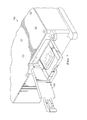
- FIGS. 6A and 6B illustrate certain aspects of mounting a hard drive sleeve 100 /hard drive 190 combination in a computer 600 , according to an embodiment of the disclosure.
- floating the mating connector avoids side loads from being applied to the connection due to mis-alignment of the connectors during insertion.
- standard SATA (and micro-SATA) connectors are blind-mateable (in other words, they have alignment features that pull the connector into the right place if a small amount of mis-alignment exists).
- the computer or tablet has a cavity to contain the movement of the hard drive connector circuit card. The cavity is designed such that the hard drive connector circuit card is allowed enough freedom of movement to not bottom out during shocks and vibration, but still allow blind-mating every time. Less clearance is provided in the axis of hard drive insertion. This ensures the electrical connection is fully mated when the drive is inserted and also ensures the electrical connection un-mates when the drive is removed.
- a connector board 612 of the connectors 610 is shown positioned inside a connector cavity 630 .
- the connector board 612 is not hard mounted to the chassis of the computer 600 . Rather, the connector cavity 630 allows slight movement of the connector board 612 such that the connector board 612 can float along with the communication interface 192 of the hard drive 190 .
- a variety of cabling may also be positioned between the remainder of the computer 600 and the connector board 612 . Such cabling may be flexible—allowing the connector 612 to float while still communicating power to the hard drive 190 along with signaling back and forth between the hard drive 190 and the computer 600 .
- the connector board 612 While allowing slight movement, the connector board 612 still allows a blind mating connection between the communication interface 192 and the connector board 612 .
- FIG. 6B also shows how a cavity 640 of the computer or tablet may have a similar profile to the hard drive sleeve 100 .
- the outside profile of the sleeve 100 is a line-to-line fit inside the cavity 640 such that the hard drive 190 can't rattle around.
- the hard drive 190 can float within the sleeve 100 when the sleeve 100 compresses and absorbs shock and vibration. When such floating happens, the connector board 612 and the communication interface 192 float along with the hard drive 190 .
- the term “or” is inclusive, meaning and/or.
- controller means any device, system or part thereof that controls at least one operation, such a device may be implemented in hardware, firmware or software, or some combination of at least two of the same. It should be noted that the functionality associated with any particular controller may be centralized or distributed, whether locally or remotely
Landscapes
- Engineering & Computer Science (AREA)
- Computer Hardware Design (AREA)
- Theoretical Computer Science (AREA)
- General Engineering & Computer Science (AREA)
- Human Computer Interaction (AREA)
- Physics & Mathematics (AREA)
- General Physics & Mathematics (AREA)
- Power Engineering (AREA)
- Casings For Electric Apparatus (AREA)
- Microelectronics & Electronic Packaging (AREA)
Abstract
Description
Claims (20)
Priority Applications (2)
| Application Number | Priority Date | Filing Date | Title |
|---|---|---|---|
| US13/953,365 US9171582B2 (en) | 2013-07-29 | 2013-07-29 | Rugged hard drive |
| PCT/US2014/040020 WO2015017017A1 (en) | 2013-07-29 | 2014-05-29 | Rugged hard drive |
Applications Claiming Priority (1)
| Application Number | Priority Date | Filing Date | Title |
|---|---|---|---|
| US13/953,365 US9171582B2 (en) | 2013-07-29 | 2013-07-29 | Rugged hard drive |
Publications (2)
| Publication Number | Publication Date |
|---|---|
| US20150029655A1 US20150029655A1 (en) | 2015-01-29 |
| US9171582B2 true US9171582B2 (en) | 2015-10-27 |
Family
ID=51062943
Family Applications (1)
| Application Number | Title | Priority Date | Filing Date |
|---|---|---|---|
| US13/953,365 Active 2034-01-02 US9171582B2 (en) | 2013-07-29 | 2013-07-29 | Rugged hard drive |
Country Status (2)
| Country | Link |
|---|---|
| US (1) | US9171582B2 (en) |
| WO (1) | WO2015017017A1 (en) |
Families Citing this family (1)
| Publication number | Priority date | Publication date | Assignee | Title |
|---|---|---|---|---|
| CN107861568B (en) * | 2017-11-02 | 2020-12-11 | 深圳信息职业技术学院 | A protective device for a laptop hard disk |
Citations (6)
| Publication number | Priority date | Publication date | Assignee | Title |
|---|---|---|---|---|
| US5155663A (en) | 1990-02-19 | 1992-10-13 | Fuji Photo Film Co., Ltd. | Memory cartridge system with adapter |
| US6011217A (en) | 1997-11-14 | 2000-01-04 | Hon Hai Precision Ind. Co., Ltd. | Card carriage bracket |
| US6094342A (en) * | 1997-11-03 | 2000-07-25 | Seagate Technology, Inc. | Disk drive jacket |
| US6567265B1 (en) * | 1995-11-20 | 2003-05-20 | Matsushita Electric Industrial Co., Ltd. | Apparatus having flexible mounting mechanism |
| US20070091504A1 (en) * | 2005-10-25 | 2007-04-26 | Prostor, Inc. | Removable data cartridge |
| US20120026674A1 (en) | 2010-07-28 | 2012-02-02 | Aldridge Russell W | Removable Storage System and Method |
-
2013
- 2013-07-29 US US13/953,365 patent/US9171582B2/en active Active
-
2014
- 2014-05-29 WO PCT/US2014/040020 patent/WO2015017017A1/en not_active Ceased
Patent Citations (6)
| Publication number | Priority date | Publication date | Assignee | Title |
|---|---|---|---|---|
| US5155663A (en) | 1990-02-19 | 1992-10-13 | Fuji Photo Film Co., Ltd. | Memory cartridge system with adapter |
| US6567265B1 (en) * | 1995-11-20 | 2003-05-20 | Matsushita Electric Industrial Co., Ltd. | Apparatus having flexible mounting mechanism |
| US6094342A (en) * | 1997-11-03 | 2000-07-25 | Seagate Technology, Inc. | Disk drive jacket |
| US6011217A (en) | 1997-11-14 | 2000-01-04 | Hon Hai Precision Ind. Co., Ltd. | Card carriage bracket |
| US20070091504A1 (en) * | 2005-10-25 | 2007-04-26 | Prostor, Inc. | Removable data cartridge |
| US20120026674A1 (en) | 2010-07-28 | 2012-02-02 | Aldridge Russell W | Removable Storage System and Method |
Non-Patent Citations (2)
| Title |
|---|
| International Search Report dated Sep. 1, 2014 in connection with International Patent Application No. PCT/US2014/040020, 4 pages. |
| Written Opinion of International Searching Authority dated Sep. 1, 2014 in connection with International Patent Application No. PCT/US2014/040020, 6 pages. |
Also Published As
| Publication number | Publication date |
|---|---|
| WO2015017017A1 (en) | 2015-02-05 |
| US20150029655A1 (en) | 2015-01-29 |
Similar Documents
| Publication | Publication Date | Title |
|---|---|---|
| CN105830283B (en) | Connector | |
| JP5860121B1 (en) | On-board equipment and server | |
| US20180184540A1 (en) | Server rack | |
| US9535469B2 (en) | Server cabinet and server system | |
| US20150303419A1 (en) | Battery Shelf Assembly, Power Storage System, and Assemblying Method of Battery Shelf Assembly | |
| US20150200474A1 (en) | Backplane communication system and rack assembly of the same | |
| US20180092241A1 (en) | Thermal transfer between electronic device and case | |
| US20160286678A1 (en) | Housing for expansion cards | |
| TWI475394B (en) | Transmission port module for expanding transmission capacity of a host module and computer system therwith | |
| US9171582B2 (en) | Rugged hard drive | |
| US11419224B1 (en) | Electronic assembly | |
| US9261230B2 (en) | Connection system for connecting an electronic device, in particular for an aircraft, to a test unit | |
| CN102148431B (en) | Connector | |
| US20060133034A1 (en) | Fan assembly for a power supply | |
| CN104009359B (en) | For the fast interface device and method of medical hoist tower | |
| US8947862B2 (en) | Expansion card module | |
| US10169283B2 (en) | Custom data transfer connector and adapter | |
| JP4776957B2 (en) | Device for forming an electromagnetically shielded connection | |
| US9042093B2 (en) | Electronic device with mounting apparatus for solid state disk | |
| US20150179229A1 (en) | Hard disk drive mounting device | |
| CN107230852B (en) | Electronic device | |
| US20120267443A1 (en) | Temperature controller, cable device, and temperature control unit | |
| CN105208817B (en) | Electronic device and shell | |
| US10261275B2 (en) | Baffle with optical connector | |
| CN219574307U (en) | Testing device for board card |
Legal Events
| Date | Code | Title | Description |
|---|---|---|---|
| AS | Assignment |
Owner name: RAYTHEON COMPANY, MASSACHUSETTS Free format text: ASSIGNMENT OF ASSIGNORS INTEREST;ASSIGNORS:BOPP, JAYSON K.;PALMER, SARAH L.;SIGNING DATES FROM 20130723 TO 20130725;REEL/FRAME:030897/0635 |
|
| FEPP | Fee payment procedure |
Free format text: PAYOR NUMBER ASSIGNED (ORIGINAL EVENT CODE: ASPN); ENTITY STATUS OF PATENT OWNER: LARGE ENTITY |
|
| STCF | Information on status: patent grant |
Free format text: PATENTED CASE |
|
| MAFP | Maintenance fee payment |
Free format text: PAYMENT OF MAINTENANCE FEE, 4TH YEAR, LARGE ENTITY (ORIGINAL EVENT CODE: M1551); ENTITY STATUS OF PATENT OWNER: LARGE ENTITY Year of fee payment: 4 |
|
| AS | Assignment |
Owner name: ROYAL BANK OF CANADA, CANADA Free format text: FIRST LIEN SECURITY AGREEMENT;ASSIGNOR:VERTEX AEROSPACE LLC;REEL/FRAME:058342/0046 Effective date: 20211206 Owner name: ROYAL BANK OF CANADA, CANADA Free format text: SECOND LIEN SECURITY AGREEMENT;ASSIGNOR:VERTEX AEROSPACE LLC;REEL/FRAME:058342/0027 Effective date: 20211206 |
|
| AS | Assignment |
Owner name: ALLY BANK, AS COLLATERAL AGENT, NEW YORK Free format text: SECURITY AGREEMENT;ASSIGNOR:VERTEX AEROSPACE, LLC;REEL/FRAME:058957/0428 Effective date: 20211206 |
|
| AS | Assignment |
Owner name: VERTEX AEROSPACE LLC, WISCONSIN Free format text: ASSIGNMENT OF ASSIGNORS INTEREST;ASSIGNOR:RAYTHEON COMPANY;REEL/FRAME:059436/0396 Effective date: 20220113 |
|
| AS | Assignment |
Owner name: BANK OF AMERICA, N.A., AS COLLATERAL AGENT, TEXAS Free format text: INTELLECTUAL PROPERTY SECURITY AGREEMENT;ASSIGNORS:VERTEX AEROSPACE LLC;VECTRUS SYSTEMS CORPORATION;ADVANTOR SYSTEMS, LLC;AND OTHERS;REEL/FRAME:062886/0877 Effective date: 20230228 |
|
| AS | Assignment |
Owner name: ADVANTOR SYSTEMS, LLC, FLORIDA Free format text: RELEASE OF SECOND LIEN INTELLECTUAL PROPERTY SECURITY AGREEMENTS;ASSIGNOR:ROYAL BANK OF CANADA;REEL/FRAME:062903/0736 Effective date: 20230228 Owner name: VECTRUS SYSTEMS CORPORATION, COLORADO Free format text: RELEASE OF SECOND LIEN INTELLECTUAL PROPERTY SECURITY AGREEMENTS;ASSIGNOR:ROYAL BANK OF CANADA;REEL/FRAME:062903/0736 Effective date: 20230228 Owner name: VERTEX AEROSPACE LLC, MISSISSIPPI Free format text: RELEASE OF SECOND LIEN INTELLECTUAL PROPERTY SECURITY AGREEMENTS;ASSIGNOR:ROYAL BANK OF CANADA;REEL/FRAME:062903/0736 Effective date: 20230228 |
|
| AS | Assignment |
Owner name: ADVANTOR SYSTEMS, LLC, FLORIDA Free format text: RELEASE BY SECURED PARTY;ASSIGNOR:ROYAL BANK OF CANADA;REEL/FRAME:062927/0079 Effective date: 20230228 Owner name: VECTRUS SYSTEMS CORPORATION, COLORADO Free format text: RELEASE BY SECURED PARTY;ASSIGNOR:ROYAL BANK OF CANADA;REEL/FRAME:062927/0079 Effective date: 20230228 Owner name: VERTEX AEROSPACE LLC, MISSISSIPPI Free format text: RELEASE BY SECURED PARTY;ASSIGNOR:ROYAL BANK OF CANADA;REEL/FRAME:062927/0079 Effective date: 20230228 Owner name: ADVANTOR SYSTEMS, LLC, FLORIDA Free format text: RELEASE BY SECURED PARTY;ASSIGNOR:ALLY BANK, AS COLLATERAL AGENT;REEL/FRAME:062927/0061 Effective date: 20230228 Owner name: VECTRUS SYSTEMS CORPORATION, COLORADO Free format text: RELEASE BY SECURED PARTY;ASSIGNOR:ALLY BANK, AS COLLATERAL AGENT;REEL/FRAME:062927/0061 Effective date: 20230228 Owner name: VERTEX AEROSPACE LLC, MISSISSIPPI Free format text: RELEASE BY SECURED PARTY;ASSIGNOR:ALLY BANK, AS COLLATERAL AGENT;REEL/FRAME:062927/0061 Effective date: 20230228 |
|
| MAFP | Maintenance fee payment |
Free format text: PAYMENT OF MAINTENANCE FEE, 8TH YEAR, LARGE ENTITY (ORIGINAL EVENT CODE: M1552); ENTITY STATUS OF PATENT OWNER: LARGE ENTITY Year of fee payment: 8 |