US9160489B1 - Origin dodging for transmitted signal - Google Patents
Origin dodging for transmitted signal Download PDFInfo
- Publication number
- US9160489B1 US9160489B1 US14/482,531 US201414482531A US9160489B1 US 9160489 B1 US9160489 B1 US 9160489B1 US 201414482531 A US201414482531 A US 201414482531A US 9160489 B1 US9160489 B1 US 9160489B1
- Authority
- US
- United States
- Prior art keywords
- symbol
- dodging
- transmission sequence
- samples
- origin
- Prior art date
- Legal status (The legal status is an assumption and is not a legal conclusion. Google has not performed a legal analysis and makes no representation as to the accuracy of the status listed.)
- Expired - Fee Related
Links
Images


Classifications
-
- H—ELECTRICITY
- H04—ELECTRIC COMMUNICATION TECHNIQUE
- H04L—TRANSMISSION OF DIGITAL INFORMATION, e.g. TELEGRAPHIC COMMUNICATION
- H04L1/00—Arrangements for detecting or preventing errors in the information received
- H04L1/004—Arrangements for detecting or preventing errors in the information received by using forward error control
- H04L1/0041—Arrangements at the transmitter end
- H04L1/0042—Encoding specially adapted to other signal generation operation, e.g. in order to reduce transmit distortions, jitter, or to improve signal shape
-
- H—ELECTRICITY
- H04—ELECTRIC COMMUNICATION TECHNIQUE
- H04B—TRANSMISSION
- H04B1/00—Details of transmission systems, not covered by a single one of groups H04B3/00 - H04B13/00; Details of transmission systems not characterised by the medium used for transmission
- H04B1/02—Transmitters
- H04B1/04—Circuits
- H04B1/0475—Circuits with means for limiting noise, interference or distortion
-
- H—ELECTRICITY
- H04—ELECTRIC COMMUNICATION TECHNIQUE
- H04L—TRANSMISSION OF DIGITAL INFORMATION, e.g. TELEGRAPHIC COMMUNICATION
- H04L27/00—Modulated-carrier systems
- H04L27/18—Phase-modulated carrier systems, i.e. using phase-shift keying
- H04L27/20—Modulator circuits; Transmitter circuits
Definitions
- NFC Near field communication
- PSK phase-shift keying
- a PSK symbol's phase correlates to a particular symbol (e.g, in D8PSK, 45 degrees corresponds to 110, 90 degrees corresponds to 010, and so on).
- Constellation diagrams are used to represent PSK symbols in the I-Q plane based on the symbols' real and imaginary components. In the constellation diagram, the real component is graphed along the I axis and the imaginary component is graphed along the Q axis. Before a signal corresponding to a succession of PSK symbols is transmitted, the signal is filtered to so that the transmitted signal transitions smoothly from one symbol to the next.
- this specification discloses an apparatus.
- the apparatus includes origin dodging logic configured to receive a transmission sequence for transmission to a receiver.
- the transmission sequence includes a sequence of transmit symbols and each transmit symbol corresponds to a coordinate pair positioning the transmit symbol's phase on an I-Q plane.
- the apparatus is configured to sample and filter the transmission sequence to create transition samples and determine whether any transition sample is within a predetermined radius of an origin of the I-Q plane.
- the apparatus is configured to generate a dodging symbol and insert the dodging symbol into the transmission sequence to create a modified transmission sequence.
- the modified transmission sequence is filtered and sampled to produce filtered samples.
- a filtered signal that includes the filtered samples is provided.
- this specification discloses a method for performing origin dodging in a transmitted signal.
- the method includes receiving a transmission sequence for transmission to a receiver.
- the transmission sequence includes a sequence of transmit symbols and each transmit symbol corresponds to a coordinate pair positioning the transmit symbol's phase on an I-Q plane.
- the method includes sampling and filtering the transmission sequence to create transition samples and determining whether any transition sample is within a predetermined radius of an origin of the I-Q plane.
- the method includes generating a dodging symbol and inserting the dodging symbol into the transmission sequence to create a modified transmission sequence.
- a filtered signal that includes filtered samples of the modified transmission sequence is provided.
- this specification discloses a device for performing origin dodging in a transmitted signal.
- the device includes first and second integrated circuits.
- the first integrated circuit is configured to receive a transmission sequence for transmission to a receiver.
- the transmission sequence includes a sequence of transmit symbols, and each transmit symbol corresponds to a coordinate pair positioning the transmit symbol's phase on an I-Q plane.
- the first integrated circuit is configured to sample and filter the transmission sequence to create transition samples and determine whether any transition sample is within a predetermined radius of an origin of the I-Q plane.
- the first integrated circuit When a transition sample between a first transmit symbol and a second transmit symbol is positioned within the radius, the first integrated circuit is configured to generate a dodging symbol and insert the dodging symbol into the transmission sequence between the first transmit symbol and the second transmit symbol to create a modified transmission sequence.
- the first integrated circuit is configured to produce filtered samples based, at least in part, on the modified transmission sequence and create a filtered signal that includes the filtered samples.
- the second integrated circuit is configured to transmit the filtered signal.
- FIG. 1A illustrates one embodiment of an apparatus associated with origin dodging for a transmitted signal.
- FIG. 1B illustrates a prior art filter used to filter a transmitted signal.
- FIG. 1C illustrates an I-Q plane plot depicting a filtered signal corresponding to a transition between two PSK symbols that are separated by 180 degrees.
- FIG. 1D illustrates an I-Q plane plot depicting the filtered signal of FIG. 1C as adjusted by the origin dodging technique disclosed herein.
- FIG. 2 illustrates one embodiment of origin dodging logic.
- FIG. 3 illustrates one embodiment of distance estimation logic.
- FIG. 4 illustrates one embodiment of dodge decision logic.
- FIGS. 5A , 5 B, 5 C illustrate alternative embodiments of dodge filter logic.
- FIG. 6 illustrates one embodiment of a method associated with origin dodging for a transmitted signal.
- FIG. 7 illustrates one embodiment of a device associated with origin dodging for a transmitted signal.
- the filtered signal derived from a succession of transmit symbols is, by design, smooth on the I-Q plane. However, when the filtered signal passes near the origin, the filtered signal can have abrupt jumps in phase and amplitude. When consecutive transmit symbols differ by a phase of 180 degrees, the filtered signal corresponding to the consecutive transmit symbols will cross near the origin of the I-Q plane. Later stages of the transmit path, such as the power amplifier can have difficulties tracking these abrupt changes and can generate unwanted distortion, both in the transmit channel as well as in adjacent channels.
- Described herein are examples of systems, methods, and other embodiments associated with adjusting a filtered signal that encodes transmit symbols so that the filtered signal does not cross through or near an origin of the I-Q plane.
- the adjustments made to the filtered signal avoid abrupt phase and amplitude changes associated with crossing near the origin, thus preventing the creation of distortion in later stages of the transmitter. This intentional distortion of the filtered signal may be preferable over downstream distortions which can be more severe and harder to predict or mitigate.
- the adjustments to the filtered signal described herein can be introduced in the transmit channel or placed in adjacent channels, or some combination of the two.
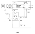
- an apparatus 100 that is associated with origin dodging for transmitted signals.
- the apparatus 100 may be implemented in a network communication device that includes a transmitter (not shown) that transmits the filtered signal output by the apparatus 100 .
- the apparatus 100 is implemented on a chip including one or more integrated circuits configured to perform one or more of the functions described herein.
- the apparatus 100 processes a transmission sequence of PSK symbols from a symbol source 110 .
- the symbol source 110 is a DPSK symbol source followed by an accumulator.
- Each symbol corresponds to the phase of a PSK symbol that is being transmitted, referred to hereinafter as a “transmit symbol”.
- the phase of each PSK symbol communicates a selected one of several possible PSK symbols.
- the PSK symbols are enhanced data rate 3 (EDR3) symbols.
- a translation block 120 translates the transmit symbols into real and imaginary coordinates that can be used to plot the samples on the I-Q plane.
- the cosine block outputs the real component, also referred to as the “I” component and the sine block outputs the imaginary component, also referred to as the “Q” component.
- the sequence of translated transmit symbols (known hereinafter as the “transmission sequence) is sampled and filtered to produce a sequence of “filtered samples” that define the filtered signal.
- the filtered signal defines a trajectory of the transitions between the transmit symbols.
- a filtered sample that is part of the trajectory between a first and second transmit symbols is referred to herein as being “between” the first and second transmit symbols.
- the real components and the imaginary components of the translated transmit symbols are input to origin dodging logic 130 that, in essence, inserts dodging symbols into the sequence of transmit symbols, when deemed necessary, so that the filtered signal that is output by the apparatus 100 does not cross the origin of the I-Q plane.
- the origin dodging logic 130 is configured to determine whether the filtered signal will fall within a predetermined radius of the origin of the constellation diagram.
- the origin dodging logic 130 is configured to generate a dodging symbol that, when inserted between the transmit symbols prior to filtering, will displace the filtered signal outside the radius.
- the dodging logic 130 combines samples of the dodging symbol with the transmission sequence and creates a modified filtered signal based on the combination of dodging symbol samples and the transmit symbol samples. The addition of the dodging symbol samples to the transmission sequence displaces the trajectory of the filtered signal away from the origin.
- FIG. 1B illustrates a prior art filter that does not adjust the filtered signal to avoid origin crossings.
- the prior art filter would be in place of the dodging logic 130 shown in FIG. 1A .
- the prior art filter includes an upsampling block and a pulse shape filter (PSF) for the I and Q components.
- PSF pulse shape filter
- the output of the prior art filter is the filtered signal, which will be susceptible to origin crossings.
- FIG. 1C illustrates filtered samples that result from two consecutive symbols ⁇ A,B ⁇ that differ in phase by 180 degrees.
- the x's represent filtered samples and the dashed line illustrates the trajectory of the filtered signal as defined by the filtered samples. It can be seen that at least one of the filtered samples indicated by a bold x) is positioned near the origin of the I-Q plane.
- FIG. 1D illustrates a trajectory of a modified filtered signal that results from injecting a dodging symbol “D” between transmit symbols A and B to generate the filtered samples. In the modified filtered signal, the near-origin samples in the original filtered signal no longer fall near the origin.
- the origin dodging logic 130 is configured to output the modified filtered signal for transmission to a receiver.
- FIG. 2 illustrates one embodiment of the origin dodging logic 130 .
- the origin dodging logic 130 includes distance estimation logic 210 , dodge decision logic 220 , and dodge filter logic 230 .
- the distance estimation logic 210 inputs the real and imaginary components of the transmission sequence as well as the direction of the trajectory of the transmission sequence.
- the distance estimation logic 210 samples an interval between transmit symbols to produce transition samples.
- the distance estimation logic 210 determines a distance between the origin and a transition sample that comes closest to the origin and outputs that distance as the variable “height.”
- the dodge decision logic 220 inputs the height and a predetermined and/or programmable radius that defines a region around the origin where filtered samples should not fall.
- the dodge decision logic 220 also has an optional “cross” input that communicates whether the phase difference between consecutive samples is 180 degrees.
- the dodge decision logic 220 inputs the phase of the transmitted symbols “p” to be used to determine a phase of the trajectory of the filtered signal.
- the phase of the trajectory is used to determine which direction to rotate the phase of a transition sample to create a dodging symbol.
- the dodge decision logic 220 generates and outputs real and imaginary components of a dodging symbol that is added “between” consecutive transmit symbols when a filtered signal will fall too close to the origin.
- the dodge filter logic 230 inputs the real and imaginary components of the transmission sequence and the real and imaginary components of the dodging symbol.
- the dodge filter logic 230 combines the transmission sequence and the dodging symbol, filters the combination, and outputs this modified filtered signal that will be transmitted to the receiver.
- the distance estimation logic 210 includes three PSF filters 310 , such as square root raised cosine (SRRC) filters.
- the filters 310 are similar to the PSFs in the dodge filter logic 230 and thus the output of the filters 310 reflects the output of the PSFs in the dodging filter 230 at the “middle” of each interval between pairs of consecutive symbols in transmission sequence (e.g, in the illustrated embodiment, the filters 310 sample the transmission sequence at 7/16, 8/16, and 9/16 th of the time interval between each pair of transmit symbols) to produce transition samples. This middle portion of the interval between consecutive symbols is selected because it is this portion of the interval that will include the filtered samples that pass closest to the origin.
- SRRC square root raised cosine
- the other portions of the interval or the entire interval may be sampled and filtered by the filters 310 .
- the filters 310 “predict” the middle portion of the filtered signal that result if origin dodging were not performed, so that a determination can be made as to whether any of the filtered samples in the filtered signal will pass too close to the origin.
- Rotation blocks 320 input the filtered real and imaginary components of the samples (e.g., the “trajectory” of transition samples) and the phase of a prior symbol (e.g., the direction input, see FIG. 2 ).
- the rotation blocks 320 rotate the transition samples by the phase of the prior symbol so that the trajectory of transition samples lies parallel to the real axis.
- the minimum distance is presumed to be the rotated transition sample having a real component that falls nearest the imaginary axis.
- the real components of transition samples are output to absolute value blocks 330 and a comparator 340 that identifies the rotation block that output the lowest real component.
- the imaginary component output by the identified rotation block is selected by a selector 350 and output as the “height” by the distance estimation logic 210 .
- the height corresponds to the imaginary component of the closest rotated transition sample in the trajectory to the origin.
- FIG. 4 illustrates one embodiment of the dodge decision logic 220 .
- the dodge decision logic 220 inputs the height determined by the distance estimation logic 210 and the value of the programmable radius parameter that may be set by a user. The height will be used to generate a dodging symbol (DS) that lies at +/ ⁇ 90 degrees to the original trajectory of the symbol samples evaluated by the distance estimation logic 210 .
- the decision whether to rotate +90 degrees or ⁇ 90 degrees is based on which direction requires the minimum magnitude to get the trajectory of filtered samples outside the radius. The effect of prior dodging symbols may be taken into account in this decision.
- the dodge decision logic 220 is enabled by AND logic 410 that outputs a value of one when the distance is less than the radius and there is a difference of 180 degrees between consecutive transmit symbols (e.g., indicating that an origin crossing will likely occur).
- the dodge decision logic may be enabled whenever the height is less than the radius, and no check is made as to whether there is a difference of 180 degrees between the first transmit symbol and the second transmit symbol.
- the dodge decision logic 220 will output real and imaginary components of a dodging symbol to be inserted into the transmission sequence.
- the dodge decision logic 210 includes logic 420 that determines which direction to rotate the phase of the transition sample trajectory to generate the dodging symbol.
- the logic 420 determines which of the two quantities r-h- ⁇ or ⁇ r-h- ⁇ is smaller, where a is the residual effect that a dodging symbol inserted into the previous interval has in the current interval.
- the parameter “memweight” is a programmable parameter memory weight that specifies how much affect a prior value of the minimum is given when determining the minimum.
- the minimum of r-h- ⁇ and ⁇ r-h- ⁇ is output to a rotation operation 440 that rotates the minimum by 90 degrees (note that “p” is the phase of the transmit symbol as can be seen in FIG. 2 ).
- the output dodging symbol corresponds to a symbol at a distance the minimum of r-h- ⁇ and ⁇ r-h- ⁇ rotated by 90 degrees from the phase of the trajectory between the transmit symbols.
- FIG. 5A illustrates one embodiment of the dodge filter logic 230 .
- the dodge filter logic 230 outputs the modified filtered signal that results from the injection of samples of the dodging symbol into samples of the transmission sequence.
- the dodge filter logic 230 includes a first upsample and delay block 510 that first upsamples to a filter rate (e.g., times 8 in the illustrated embodiment) and then delays by half a symbol period (e.g., 4 in the illustrated embodiment) the real and imaginary components of the dodging symbol.
- a filter rate e.g., times 8 in the illustrated embodiment
- a symbol period e.g., 4 in the illustrated embodiment
- the dodge filter logic 230 includes a second upsample and delay block 515 that first delays by some predetermined period (e.g., 4 was selected as the delay period in the illustrated embodiment to balance the delay of deciding on and creating a dodging symbol) and then upsamples to the filter rate the real and imaginary components the transmit symbols in the transmission sequence.
- the relative position of the delay elements in the upsample and delay blocks 510 , 515 places the dodging symbol samples in between the samples in the transmission sequence.
- This combined sequence of samples is filtered by PSFs 530 , resulting in a filtered signal that lies in the transmit channel and that avoids the origin as shown in FIG. 1D .
- the PSF 530 is an SRRC filter.
- FIG. 5B illustrates another embodiment of the dodge filter logic 230 .
- a separate dodge filter 520 filters the dodging symbol samples and the filtered dodging symbol samples are then combined with the filtered transmission sequence samples to produce the modified filtered signal.
- the dodge filter 520 can be selected to have an attenuated response in-channel, and to have a majority of passband in adjacent channels.
- FIG. 5C illustrates another embodiment of the dodge filter logic 230 .
- the dodge filter's response is parameterized according to programmable parameters alpha 1 and alpha 2 .
- a first proportion of the dodging symbol (as determined by alpha 1 ) is sent to the transmit channel and a second proportion of the dodging symbol (as determined by alpha 2 ) is sent to the adjacent channels.
- FIG. 6 illustrates one embodiment of a method 600 for performing origin dodging to reduce power leakage caused by origin crossing in a transmitted filtered signal.
- the method 600 includes, at 610 , receiving a transmission sequence for transmission to a receiver.
- the transmission sequence includes a sequence of transmit symbols and each transmit symbol corresponds to a coordinate pair positioning the transmit symbol's phase on an I-Q plane.
- the method includes sampling and filtering the transmission sequence to create transition samples.
- the method includes determining whether any transition sample is within a predetermined radius of an origin of the I-Q plane. If no transition sample is within the radius, the method continues to 650 where a filtered signal is provided for transmission.
- the method includes generating a dodging symbol and at 640 inserting the dodging symbol into the transmission sequence to create a modified transmission sequence.
- a filtered signal that includes filtered samples of the modified transmission sequence is provided.
- FIG. 7 illustrates one embodiment of a device 700 that performs origin dodging to reduce power leakage of a transmitted signal into adjacent channels.
- the device 700 embodies the apparatus 100 illustrated in FIGS. 1-5 .
- the logics of FIGS. 2-5 are illustrated in FIG. 7 as part of the first integrated circuit 730 .
- the various logics could be distributed in several integrated circuits or implemented on an integrated circuit that also performs other functions.
- the device 700 includes a first integrated circuit 730 and a second integrated circuit 740 .
- the first integrated circuit 730 is configured to input a transmission sequence for transmission to a receiver, wherein the transmission sequence includes a sequence of transmit symbols, wherein each transmit symbol corresponds to a coordinate pair positioning the transmit symbol's phase on an I-Q plane.
- the first integrated circuit 730 is configured to sample and filter the transmission sequence to create transition samples.
- the first integrated circuit 730 is also configured to input a programmable radius defining a region around an origin of the I-Q plane in which the filtered signal should not be positioned.
- the first integrated circuit 730 is configured to identify a transition sample that falls within the region and when a transition sample falls within the region, generate a dodging symbol.
- the first integrated circuit 730 is configured to insert the dodging symbol into the transmission sequence between the first transmit symbol and the second transmit symbol to create a modified transmission sequence; produce filtered samples based, at least in part, on the modified transmission sequence; and create a filtered signal that includes the filtered samples.
- the second integrated circuit 740 includes a transmitter 710 that is configured to transmit the filtered signal.
- references to “one embodiment”, “an embodiment”, “one example”, “an example”, and so on, indicate that the embodiment(s) or example(s) so described may include a particular feature, structure, characteristic, property, element, or limitation, but that not every embodiment or example necessarily includes that particular feature, structure, characteristic, property, element or limitation. Furthermore, repeated use of the phrase “in one embodiment” does not necessarily refer to the same embodiment, though it may.
- Computer storage medium as used herein is a non-transitory medium that stores instructions and/or data.
- a computer storage medium may take forms, including, but not limited to, non-volatile media, and volatile media.
- Non-volatile media may include, for example, optical disks, magnetic disks, and so on.
- Volatile media may include, for example, semiconductor memories, dynamic memory, and so on.
- Common forms of a computer storage media may include, but are not limited to, a floppy disk, a flexible disk, a hard disk, a magnetic tape, other magnetic medium, an ASIC, a CD, other optical medium, a RAM, a ROM, a memory chip or card, a memory stick, and other electronic media that can store computer instructions and/or data.
- Computer storage media described herein are limited to statutory subject matter under 35 U.S.C ⁇ 101.
- Logic as used herein includes a computer or electrical hardware component(s), firmware, a non-transitory computer storage medium that stores instructions, and/or combinations of these components configured to perform a function(s) or an action(s), and/or to cause a function or action from another logic, method, and/or system.
- Logic may include a microprocessor controlled by an algorithm, a discrete logic (e.g., ASIC), an analog circuit, a digital circuit, a programmed logic device, a memory device containing instructions that when executed perform an algorithm, and so on.
- Logic may include one or more gates, combinations of gates, or other circuit components. Where multiple logics are described, it may be possible to incorporate the multiple logics into one physical logic component. Similarly, where a single logic unit is described, it may be possible to distribute that single logic unit between multiple physical logic components. Logic as described herein is limited to statutory subject matter under 35 U.S.C ⁇ 101.
- illustrated methodologies are shown and described as a series of blocks. The methodologies are not limited by the order of the blocks as some blocks can occur in different orders and/or concurrently with other blocks from that shown and described. Moreover, less than all the illustrated blocks may be used to implement an example methodology. Blocks may be combined or separated into multiple components. Furthermore, additional and/or alternative methodologies can employ additional actions that are not illustrated in blocks. The methods described herein are limited to statutory subject matter under 35 U.S.C ⁇ 101.
Landscapes
- Engineering & Computer Science (AREA)
- Computer Networks & Wireless Communication (AREA)
- Signal Processing (AREA)
- Digital Transmission Methods That Use Modulated Carrier Waves (AREA)
Abstract
Description
Claims (17)
Priority Applications (1)
| Application Number | Priority Date | Filing Date | Title |
|---|---|---|---|
| US14/482,531 US9160489B1 (en) | 2013-09-10 | 2014-09-10 | Origin dodging for transmitted signal |
Applications Claiming Priority (2)
| Application Number | Priority Date | Filing Date | Title |
|---|---|---|---|
| US201361875886P | 2013-09-10 | 2013-09-10 | |
| US14/482,531 US9160489B1 (en) | 2013-09-10 | 2014-09-10 | Origin dodging for transmitted signal |
Publications (1)
| Publication Number | Publication Date |
|---|---|
| US9160489B1 true US9160489B1 (en) | 2015-10-13 |
Family
ID=54252796
Family Applications (1)
| Application Number | Title | Priority Date | Filing Date |
|---|---|---|---|
| US14/482,531 Expired - Fee Related US9160489B1 (en) | 2013-09-10 | 2014-09-10 | Origin dodging for transmitted signal |
Country Status (1)
| Country | Link |
|---|---|
| US (1) | US9160489B1 (en) |
Citations (1)
| Publication number | Priority date | Publication date | Assignee | Title |
|---|---|---|---|---|
| US20110305292A1 (en) * | 2010-06-14 | 2011-12-15 | Toru Matsuura | Nonlinear filter and transmission circuit |
-
2014
- 2014-09-10 US US14/482,531 patent/US9160489B1/en not_active Expired - Fee Related
Patent Citations (1)
| Publication number | Priority date | Publication date | Assignee | Title |
|---|---|---|---|---|
| US20110305292A1 (en) * | 2010-06-14 | 2011-12-15 | Toru Matsuura | Nonlinear filter and transmission circuit |
Similar Documents
| Publication | Publication Date | Title |
|---|---|---|
| US8244142B2 (en) | Optical receiver having fractional sampling | |
| KR102164627B1 (en) | System of optimizing a high-speed link including a channel carrying a data signal between a transmitter and a receiver and method thereof and method of characterizing a channel between a transmitter and a receiver | |
| EP4459446A3 (en) | A codec for processing scenes of almost unlimited detail | |
| WO2019133928A8 (en) | Hierarchical, parallel models for extracting in real time high-value information from data streams and system and method for creation of same | |
| KR102317365B1 (en) | Phase shift keyed signaling tone | |
| WO2011108893A3 (en) | Method and apparatus for generating and reproducing adaptive stream based on file format, and recording medium thereof | |
| EP3101598A3 (en) | Augmented neural networks | |
| US9787468B2 (en) | LVDS data recovery method and circuit | |
| CA2810396A1 (en) | Carrying auxiliary data within audio signals | |
| CN102144405A (en) | Interaural time delay restoration system and method | |
| EP2856645A2 (en) | Low latency and low complexity phase shift network | |
| EP3881484A4 (en) | Systems and methods for managing data based on secret sharing | |
| US9160489B1 (en) | Origin dodging for transmitted signal | |
| US20230396406A1 (en) | PAM4 Threshold Phase Engine | |
| EP2523472A1 (en) | Apparatus and method and computer program for generating a stereo output signal for providing additional output channels | |
| CN108551371B (en) | Method and system for blind carrier phase estimation of QAM signal | |
| Ríos et al. | Robust output-feedback control for uncertain linear sampled-data systems: A 2D impulsive system approach | |
| CN111402905A (en) | Audio data recovery method and device and Bluetooth equipment | |
| US8903001B2 (en) | Channel estimation with decision feedback | |
| CN113497774A (en) | Frequency offset estimation method and device, electronic equipment and computer readable medium | |
| CN103560861A (en) | Constellation mapping method | |
| CN107710651A (en) | Dispensing device | |
| EP4224020A4 (en) | Flow path selection value, system and method, storage medium, and application | |
| Djurović et al. | Parameter estimation of non-uniform sampled polynomial-phase signals using the HOCPF-WD | |
| CN116629381A (en) | A federated migration learning method, device, storage medium and electronic equipment |
Legal Events
| Date | Code | Title | Description |
|---|---|---|---|
| AS | Assignment |
Owner name: MARVELL SEMICONDUCTOR, INC.,, CALIFORNIA Free format text: ASSIGNMENT OF ASSIGNORS INTEREST;ASSIGNORS:TEE, LUNS;VENKATESH, SWAROOP;SIGNING DATES FROM 20070305 TO 20140909;REEL/FRAME:036483/0105 Owner name: MARVELL INTERNATIONAL LTD., BERMUDA Free format text: ASSIGNMENT OF ASSIGNORS INTEREST;ASSIGNOR:MARVELL INDIA PVT. LTD.;REEL/FRAME:036483/0139 Effective date: 20150831 Owner name: MARVELL INDIA PVT. LTD., INDIA Free format text: ASSIGNMENT OF ASSIGNORS INTEREST;ASSIGNOR:SETHI, ANKIT;REEL/FRAME:036483/0137 Effective date: 20140909 Owner name: MARVELL INTERNATIONAL LTD., BERMUDA Free format text: ASSIGNMENT OF ASSIGNORS INTEREST;ASSIGNOR:MARVELL SEMICONDUCTOR, INC.;REEL/FRAME:036483/0118 Effective date: 20150902 |
|
| STCF | Information on status: patent grant |
Free format text: PATENTED CASE |
|
| FEPP | Fee payment procedure |
Free format text: MAINTENANCE FEE REMINDER MAILED (ORIGINAL EVENT CODE: REM.); ENTITY STATUS OF PATENT OWNER: LARGE ENTITY |
|
| LAPS | Lapse for failure to pay maintenance fees |
Free format text: PATENT EXPIRED FOR FAILURE TO PAY MAINTENANCE FEES (ORIGINAL EVENT CODE: EXP.); ENTITY STATUS OF PATENT OWNER: LARGE ENTITY |
|
| STCH | Information on status: patent discontinuation |
Free format text: PATENT EXPIRED DUE TO NONPAYMENT OF MAINTENANCE FEES UNDER 37 CFR 1.362 |
|
| FP | Lapsed due to failure to pay maintenance fee |
Effective date: 20191013 |
|
| AS | Assignment |
Owner name: CAVIUM INTERNATIONAL, CAYMAN ISLANDS Free format text: ASSIGNMENT OF ASSIGNORS INTEREST;ASSIGNOR:MARVELL INTERNATIONAL LTD.;REEL/FRAME:052918/0001 Effective date: 20191231 |
|
| AS | Assignment |
Owner name: MARVELL ASIA PTE, LTD., SINGAPORE Free format text: ASSIGNMENT OF ASSIGNORS INTEREST;ASSIGNOR:CAVIUM INTERNATIONAL;REEL/FRAME:053475/0001 Effective date: 20191231 |