US9157339B2 - Hybrid cam-camless variable valve actuation system - Google Patents

Hybrid cam-camless variable valve actuation system Download PDF

Info

Publication number
US9157339B2
US9157339B2 US14/045,490 US201314045490A US9157339B2 US 9157339 B2 US9157339 B2 US 9157339B2 US 201314045490 A US201314045490 A US 201314045490A US 9157339 B2 US9157339 B2 US 9157339B2
Authority
US
United States
Prior art keywords
valve
port
cylindrically shaped
engine
actuator
Prior art date
Legal status (The legal status is an assumption and is not a legal conclusion. Google has not performed a legal analysis and makes no representation as to the accuracy of the status listed.)
Expired - Fee Related, expires
Application number
US14/045,490
Other versions
US20140116363A1 (en
Inventor
Dale Arden Stretch
David Gerard Genise
Douglas John Nielsen
James Edward McCarthy, Jr.
Current Assignee (The listed assignees may be inaccurate. Google has not performed a legal analysis and makes no representation or warranty as to the accuracy of the list.)
Eaton Intelligent Power Ltd
Original Assignee
Eaton Corp
Priority date (The priority date is an assumption and is not a legal conclusion. Google has not performed a legal analysis and makes no representation as to the accuracy of the date listed.)
Filing date
Publication date
Priority to US14/045,490 priority Critical patent/US9157339B2/en
Application filed by Eaton Corp filed Critical Eaton Corp
Priority to KR1020157011446A priority patent/KR20150063542A/en
Priority to CN201380051996.2A priority patent/CN104704210B/en
Priority to PCT/US2013/063376 priority patent/WO2014055821A1/en
Priority to EP13785978.1A priority patent/EP2904224B1/en
Priority to JP2015535803A priority patent/JP6272334B2/en
Assigned to EATON CORPORATION reassignment EATON CORPORATION ASSIGNMENT OF ASSIGNORS INTEREST (SEE DOCUMENT FOR DETAILS). Assignors: GENISE, DAVID GERARD, MCCARTHY, JAMES EDWARD, JR., NIELSEN, DOUGLAS JOHN, STRETCH, DALE ARDEN
Publication of US20140116363A1 publication Critical patent/US20140116363A1/en
Application granted granted Critical
Publication of US9157339B2 publication Critical patent/US9157339B2/en
Priority to JP2017220010A priority patent/JP2018048644A/en
Assigned to EATON INTELLIGENT POWER LIMITED reassignment EATON INTELLIGENT POWER LIMITED ASSIGNMENT OF ASSIGNORS INTEREST (SEE DOCUMENT FOR DETAILS). Assignors: EATON CORPORATION
Expired - Fee Related legal-status Critical Current
Adjusted expiration legal-status Critical

Links

Images

Classifications

    • FMECHANICAL ENGINEERING; LIGHTING; HEATING; WEAPONS; BLASTING
    • F01MACHINES OR ENGINES IN GENERAL; ENGINE PLANTS IN GENERAL; STEAM ENGINES
    • F01LCYCLICALLY OPERATING VALVES FOR MACHINES OR ENGINES
    • F01L9/00Valve-gear or valve arrangements actuated non-mechanically
    • F01L9/10Valve-gear or valve arrangements actuated non-mechanically by fluid means, e.g. hydraulic
    • F01L9/18Means for increasing the initial opening force on the valve
    • FMECHANICAL ENGINEERING; LIGHTING; HEATING; WEAPONS; BLASTING
    • F01MACHINES OR ENGINES IN GENERAL; ENGINE PLANTS IN GENERAL; STEAM ENGINES
    • F01LCYCLICALLY OPERATING VALVES FOR MACHINES OR ENGINES
    • F01L1/00Valve-gear or valve arrangements, e.g. lift-valve gear
    • F01L1/20Adjusting or compensating clearance
    • F01L1/22Adjusting or compensating clearance automatically, e.g. mechanically
    • F01L1/24Adjusting or compensating clearance automatically, e.g. mechanically by fluid means, e.g. hydraulically
    • FMECHANICAL ENGINEERING; LIGHTING; HEATING; WEAPONS; BLASTING
    • F01MACHINES OR ENGINES IN GENERAL; ENGINE PLANTS IN GENERAL; STEAM ENGINES
    • F01LCYCLICALLY OPERATING VALVES FOR MACHINES OR ENGINES
    • F01L1/00Valve-gear or valve arrangements, e.g. lift-valve gear
    • F01L1/12Transmitting gear between valve drive and valve
    • F01L1/18Rocking arms or levers
    • F01L1/181Centre pivot rocking arms
    • F01L9/02
    • FMECHANICAL ENGINEERING; LIGHTING; HEATING; WEAPONS; BLASTING
    • F01MACHINES OR ENGINES IN GENERAL; ENGINE PLANTS IN GENERAL; STEAM ENGINES
    • F01LCYCLICALLY OPERATING VALVES FOR MACHINES OR ENGINES
    • F01L9/00Valve-gear or valve arrangements actuated non-mechanically
    • F01L9/10Valve-gear or valve arrangements actuated non-mechanically by fluid means, e.g. hydraulic
    • FMECHANICAL ENGINEERING; LIGHTING; HEATING; WEAPONS; BLASTING
    • F01MACHINES OR ENGINES IN GENERAL; ENGINE PLANTS IN GENERAL; STEAM ENGINES
    • F01LCYCLICALLY OPERATING VALVES FOR MACHINES OR ENGINES
    • F01L1/00Valve-gear or valve arrangements, e.g. lift-valve gear
    • F01L1/02Valve drive
    • F01L1/04Valve drive by means of cams, camshafts, cam discs, eccentrics or the like
    • F01L1/047Camshafts
    • F01L1/053Camshafts overhead type
    • F01L2001/0535Single overhead camshafts [SOHC]
    • FMECHANICAL ENGINEERING; LIGHTING; HEATING; WEAPONS; BLASTING
    • F01MACHINES OR ENGINES IN GENERAL; ENGINE PLANTS IN GENERAL; STEAM ENGINES
    • F01LCYCLICALLY OPERATING VALVES FOR MACHINES OR ENGINES
    • F01L3/00Lift-valve, i.e. cut-off apparatus with closure members having at least a component of their opening and closing motion perpendicular to the closing faces; Parts or accessories thereof
    • F01L2003/25Valve configurations in relation to engine
    • F01L2003/253Valve configurations in relation to engine configured parallel to piston axis
    • F01L2009/028

Definitions

  • the present disclosure concerns valve actuation systems of internal combustion engines.
  • Valve actuation systems typically involve a rotating cam that actuates engine valves directly or through mechanical devices such as rocker arms, including deactivating rocker arms and variable lift rocker arms, pushrods, hydraulic lash adjusters and tappets.
  • Such valve actuation systems are dependent on lift provided by cam lobes in order to actuate a valve from a seated position. Such dependence is exhibited in both exhaust and intake valves.
  • opening and closing of both exhaust and intake valves independently of the position of the cam can be beneficial for certain types of engine operation.
  • An internal combustion engine has a cylinder head mounted to an engine block that at least partially forms a plurality of cylinder combustion chambers.
  • the cylinder head has multiple intake ports and multiple exhaust ports. Valves regulate the passage of gas into and out of the combustion chamber.
  • Cam-operated valves are mechanically coupled to a rotating cam directly or through one or more of a variety of components that assist in transforming the rotational kinetic energy of the cam to linear motion of the valves.
  • One of the exhaust valves and one of the intake valves are mechanically coupled to the cam.
  • Electrohydraulic actuators actuate separate intake and exhaust valves of a particular cylinder. The electrohydraulic actuators are in fluid communication with a high pressure fluid source.
  • FIG. 1 illustrates a partially exploded perspective view of a valve head 100 .
  • FIG. 2 illustrates a sectional view of the valve head 100 shown in FIG. 1 along the line 2 - 2 .
  • FIG. 3 illustrates a partial sectional view of an actuator 104 and engine valve 102 shown in FIG. 1 .
  • FIGS. 4 through 6 illustrate a partial sectional view of actuator 104 in various stages of actuation along the line 4 - 4 shown in FIG. 3 .
  • FIGS. 7 through 9 illustrate graphs of engine valve displacement over the angular position of the cam for a four-valve cylinder according to the present disclosure.
  • FIG. 1 illustrates a valve head 100 according to one aspect of the present teachings.
  • the illustrated valve head 100 is configured to be mounted on an engine block of a diesel engine.
  • An engine block on which the valve head 100 can be mounted can contain piston bores. Pistons can be inserted into such bores to form combustion chambers.
  • the valve head 100 can form the top portion of the combustion chambers when mounted on the engine block.
  • the illustrated valve head 100 is for use with six cylinders of a twelve cylinder engine.
  • the twelve cylinder engine is a V-type engine having six cylinders on each side.
  • the present teachings are applicable to other engine configurations as well, such as straight engine configurations, and different numbers of cylinders more or less than twelve.
  • the present teachings are applicable to engines having six, eight and ten cylinders.
  • the valve head 100 shown in FIG. 1 includes a hybrid valve actuation system wherein both mechanical and electrohydraulic actuation mechanisms are used to open and close the engine valves of a particular cylinder.
  • the valve head 100 When mounted on an engine block, the valve head 100 forms part of six combustion chambers.
  • the head 100 includes twenty-four engine valves in total, four for each of the combustion chambers partially formed by the valve head.
  • a feed rail 101 can be mounted at the top of valve head 100 .
  • the feed rail 101 has two high pressure conduits 103 that supply high pressure hydraulic fluid to the electrohydraulic actuators 104 discussed further herein, and a low pressure drain conduit 105 that allows hydraulic fluid to flow from the electrohydraulic actuators 104 .
  • FIG. 2 illustrates a sectional view of the valve head 100 shown in FIG. 1 .
  • two of the engine valves 102 corresponding to one of the cylinders are actuated by an electrohydraulic actuator 104 .
  • the other two engine valves 102 of the cylinder are mechanically actuated by cam 112 and rocker arms 114 .
  • the valve head 100 includes intake 106 and exhaust ports 108 through which air enters and combusted gas leaves the combustion chamber, respectively, during engine operation.
  • the engine valves 102 actuated by electrohydraulic actuators 104 open and close respective passages from the combustion chamber to intake and exhaust ports 106 , 108 .
  • one of the intake ports 106 for a particular cylinder is regulated by one of the electrohydraulic actuators 104 and one of the exhaust ports 108 is also regulated by one of the electrohydraulic actuators 104 .
  • the entry and exit of gas from the combustion chamber is regulated in part by the valves 102 that are actuated mechanically and in part by valves 102 actuated by electrohydraulic actuators 104 .
  • the engine valves 102 are seated against valve seats 110 .
  • Mechanical actuation of engine valves 102 shown in FIGS. 1 and 2 is achieved through a rotating cam 112 periodically transferring motion to a rocker arm 114 , which in turn transfers linear motion to engine valves 102 .
  • Such mechanical actuation illustrates one possible type of mechanical valve actuation according to the present disclosure.
  • Other forms of mechanical actuation may also be implemented to transform the rotational motion of a cam to kinetic energy or mechanical potential energy, and ultimately to translational motion of engine valves 102 .
  • Such mechanisms include a rotating cam placed in direct contact with an engine valve 102 , or by including one or both of a lash adjuster and rocker arm between a cam and engine valve.
  • Still other combinations of various valve train components are possible in order to achieve mechanical actuation of an engine valve.
  • Such components include but are not limited to rocker arms, including deactivating rocker arms and variable lift rocker arms, pushrods, hydraulic lash adjusters and tappets.
  • FIG. 3 illustrates linear hydraulic actuator 104 , which includes a two stage hydraulic piston 302 .
  • the two stage piston 302 has a large diameter piston member 304 partially disposed within a cavity 306 of an actuator housing 308 .
  • the large diameter piston member 304 has a cylindrically-shaped piston head 310 at one end 311 in fluid communication with hydraulic fluid that fills the volume 312 .
  • the volume 312 is formed in part by the housing 308 , including the walls of the cavity 306 , the upper surface 314 of the piston head 310 and the upper surface 316 of one end 311 of a small diameter piston 318 .
  • the piston head 310 has a cylindrical shape, and the cavity 306 has a size and shape that permits a close fit between the cavity 306 and piston 304 , which in turn minimizes leaking of pressurized fluid from volume 312 .
  • the small diameter piston member 318 is disposed within a tubular piston bore 320 in the large diameter piston member 304 . Portions of the piston bore 320 have a shape complementary to the small diameter piston member 318 . This complementary shape limits the motion of the small diameter piston member 318 with respect to the large diameter piston member 304 .
  • the small diameter piston member 318 has a cylindrically shaped outer surface 322 distal to the volume 312 relative to a frustoconical outer surface 328 of the small diameter piston member 318 .
  • the large diameter piston member 304 has a cylindrically shaped inner surface 323 that has a shape complimentary to the cylindrically shaped outer surface 322 , and a frustoconical inner surface 332 that has a shape complimentary to the frustoconical outer surface 328 .
  • the complementary shapes limit the motion of the small diameter piston member 318 toward the volume 312 .
  • the small diameter piston member 318 has another cylindrically shaped outer surface 324 proximal to the volume 312 relative to the frustoconical outer surface 328 of the small diameter piston member 318 .
  • the large diameter piston member 304 also has another cylindrically shaped inner surface 330 that has a shape complimentary to the cylindrically shaped outer surface 324 proximal to volume 312 .
  • the bore 320 is narrower at stop 317 than the diameter of the cylindrically shaped outer surface 324 of small diameter piston member 318 .
  • the stop 317 thus limits the downward motion of the small diameter piston member 304 .
  • the small diameter piston 318 includes a cap 333 and an insert 335 .
  • the insert 335 comes into contact with the engine valve 102 , which contact causes the engine valve 102 to move in response to the motion of the piston 302 .
  • the insert 335 may be integrated into an engine valve 102 .
  • the actuator housing 308 of the hydraulic actuator 104 includes a valve housing 334 and a piston guide 336 .
  • the valve housing 334 is mounted above the piston guide 336 .
  • the piston 302 is partially inserted within the piston guide 336 .
  • the hydraulic actuator 104 includes a two position solenoid-based pressure valve 338 .
  • the pressure valve 338 includes a high pressure inlet 340 , and low pressure outlets 342 .
  • the pressure valve 338 also includes volume inlet ports 344 that permit fluid to enter the volume 312 from the high pressure inlet 340 , or allow fluid to exit the volume 312 through the low pressure outlets 342 .
  • the high pressure inlet 340 is in fluid communication with the high pressure fluid source, such as a high pressure feed conduit 103 of the feed rail 101 described above, while the low pressure outlets 342 are in fluid communication with the low pressure reservoir, such as the low pressure drain conduit 105 of the feed rail 101 .
  • An actuator valve such as the illustrated spool valve member 346 , regulates the flow of hydraulic fluid between the high pressure inlet 340 , low pressure outlet 342 , and volume inlet port 344 .
  • the spool valve member 346 includes a magnetic material that is responsive to magnetic fields generated by the coils 348 of a solenoid that can be activated to shift the position of the spool valve member 346 .
  • the spool valve member 346 controls whether pressurized fluid flows into volume 312 , which in turn controls actuation of the engine valve 102 coupled to the piston 302 .
  • FIGS. 4 through 6 illustrate the electrohydraulic actuator 104 in various stages of actuation.
  • the solenoid coils 348 can generate a magnetic field caused by electrical current in the coils 348 .
  • the coils 348 are not conducting current, and the spool valve member 346 is biased to the closed position to the left side of the actuator 104 . In this position, high pressure fluid is not permitted into volume 312 , while fluid in the volume 312 can exit via volume inlet port 344 and low pressure outlet 342 .
  • the spool valve member 346 has a plurality of channels 350 that wrap around the spool valve member 346 . Depending on the position of the spool valve member 346 , the channels 350 allow passage of hydraulic fluid between a high pressure inlet 340 , low pressure outlets 342 , and volume inlet ports 344 .
  • the illustrated spool valve member 346 When the illustrated spool valve member 346 is in a low pressure position as illustrated in FIG. 4 , it is shifted to the left within actuator housing 308 . In this position, the volume 312 is in fluid communication with the low pressure outlet 342 , which in turn is configured to be in fluid communication with a low pressure reservoir. In this position, fluid within the volume 312 is free to flow through the volume inlet ports 344 and the low pressure outlet 342 .
  • FIG. 5 illustrates the electrohydraulic actuator 104 in a state where the solenoid coils 348 have been activated, shifting the spool valve member 346 to the right. This allows high pressure hydraulic fluid to travel from the high pressure inlet 340 , through channels 350 of the spool valve member 346 and the volume inlet port 344 , to the volume 312 .
  • high pressure fluid fills the volume 312 .
  • the small diameter piston member 318 and large diameter piston member 304 initially move in unison.
  • the end surface 316 of the small diameter member 318 and end surface 314 of the large diameter member 304 form a large surface area acted upon by the pressurized fluid.
  • the surface area of the end surface 314 of the large diameter member 304 is about nine times larger than the surface area of the end surface 316 of the small diameter member 318 .
  • the ratio of the surface area of the end surface 314 versus the end surface 316 can be between about eight to ten.
  • the large surface area results in a greater force applied by the high pressure hydraulic fluid than would be applied to a piston having a smaller surface area in pressure communication with volume 312 .
  • This increased force can assist in overcoming the opposing force applied to the engine valves 102 as a result of the pressure differential between the combustion chamber and the exhaust or intake ports, which force can be substantial even when the pressure differential is small.
  • the piston head 310 of the large diameter piston member 304 is in contact with the guide 336 , and thus the downward motion of the large diameter piston member 304 has stopped.
  • the small diameter piston member is not inhibited by the large diameter piston member's 304 contact with the guide 336 .
  • the small diameter piston member 318 moves independently of the large diameter piston member 304 and continues to move downwardly.
  • the small diameter piston member 318 can continue downwardly until the cap 333 makes contact with the stop 317 .
  • the engine valve 102 reaches a fully opened position when the cap 333 contacts the stop 317 and the large diameter piston member 304 has made contact with the guide 336 .
  • the small diameter piston member 318 moves upwardly until the frustoconical inner surface 332 meets the frustoconical outer surface 328 .
  • the large diameter piston member 304 and the small diameter piston member 318 then move in unison.
  • a greater volume of hydraulic fluid is displaced for every unit of length the engine valve 102 moves relative to the volume displaced when only the small diameter piston member 318 is moving. This results in a greatly reduced seating velocity of the engine valve 102 because there is a greater pressure drop with a greater amount of displaced fluid.
  • the rate of fluid flow will also depend on the size of high pressure inlet 340 , low pressure outlets 342 and volume inlet port 344 .
  • FIG. 7 illustrates engine valve lift for four engine valves of an engine cylinder measured in arbitrary standard units of length versus degrees of cam angular rotation.
  • Line 700 corresponds to a cam-actuated exhaust valve and line 702 corresponds to a cam-actuated intake valve. Both of the engine valves represented by lines 700 and 702 are actuated at common points during the rotation of the cam.
  • Lines 704 a , 704 b and 704 c correspond to the various points of actuation of the electrohydraulically actuated exhaust valves according to the present teachings.
  • Line 704 a and 704 b represent two possible valve opening profiles of electrohydraulically driven exhaust valves opening earlier than the cam-actuated exhaust valve 700 . This type of early opening of the exhaust valves can be referred to as early exhaust valve opening or “EEVO.”
  • the electrohydraulically actuated exhaust valve can also follow the cam-actuated exhaust valve profile as shown by line 704 c.
  • the electrohydraulically driven intake valve 706 may also be controlled independently of the cam-actuated intake valve 702 . As shown by curves 706 a and 706 b , the intake valves may be kept open longer than the corresponding cam-actuated intake valve 702 . Such intake valve actuation can be referred to as late intake valve closing or “LIVC.” The electrohydraulically driven intake valve may also follow the cam-actuated intake valve profile as shown by line 706 c.
  • FIG. 8 illustrates engine valve lift for four valves of an engine cylinder exhibiting deactivation of the electrohydraulically actuated engine valves.
  • the cam-actuated exhaust valve 800 and intake valve 802 operate normally, while the electrohydraulically actuated intake valves 804 and exhaust valves 806 are deactivated, and therefore stay closed.
  • This engine valve management provides for greater velocity of the intake and exhaust gases. This can provide for improved swirl control, which can improve diffusion of fuel within the combustion chamber.
  • deactivation of these valves reduces power consumed to generate the hydraulic pressure required to actuate the valves.
  • FIG. 9 illustrates another engine valve lift profile for four valves of an engine cylinder.
  • the cam-actuated exhaust valve 900 and the electrohydraulically driven exhaust valve 902 open during common points in the cam cycle, for example between ⁇ 120 degrees to 60 degrees.
  • the cam-actuated intake valve 904 and the electrohydraulically driven intake valve 906 open during common points in the cam cycle.
  • the electrohydraulically driven intake valve may close at various points after the cam-actuated intake valve is closed, or at the same time as the cam-actuated intake valve as shown by lines 906 a , 906 b and 906 c .
  • the electrohydraulically driven exhaust valve may be opened while the intake valves are open, as shown by line 908 . This recirculates the exhaust gas into the combustion chamber.
  • Such cylinder engine valve management can be referred to as exhaust gas recirculation, or “EGR.”
  • Engine braking may also be performed by the electrohydraulically actuated engine valves by opening the electrohydraulically actuated exhaust engine valve during a compression stroke as shown by line 910 , thus removing energy from the cylinder.
  • the amount of displacement of the engine valves for can vary. Variable displacement of a particular valve 102 can be performed by a solenoid valve having two different actuation states, one effecting an engine valve displacement of a particular length and the second effecting an engine valve displacement of a different length. Such variation can also be achieved, for example, by including a second electrohydraulically actuated exhaust valve.
  • the electrohydraulic actuator 104 can be utilized to provide variable displacement of a particular valve 102 , such as between a closed position ( FIG. 4 ), an intermediate lift position ( FIG. 5 ), and a fully opened position ( FIG. 6 ).
  • the level of pressure of the high pressure fluid provided to the volume 312 can be varied to provide such variable valve lift. Varying the level of pressure of the high pressure fluid provided to the volume 312 can be performed, e.g., by the magnetic spool valve member 346 , as well as by adjusting the pressure of the high pressure fluid provided to the high pressure inlet 340 directly.
  • the valve 102 When the level of pressure of the high pressure fluid is below a first threshold (such as by not providing high pressure fluid to the volume 312 ), the valve 102 can remain in the closed position shown in FIG. 4 .
  • the first threshold can correspond to a level of pressure of approximately 1,700 pounds per square inch. If the level of pressure of the high pressure fluid provided to the volume 312 is above the first threshold corresponding to the closed state, but below a second threshold, the valve 102 can be actuated to the intermediate lift position shown in FIG. 5 .
  • the intermediate lift position corresponds to a pressure sufficient to move the small diameter piston member 318 and large diameter piston member 304 in unison, but not separately.
  • the second threshold can correspond to a level of pressure of approximately 2,000 pounds per square inch.
  • the end surface 316 of the small diameter member 318 and the end surface 314 of the large diameter member 304 form a large surface area acted upon by the high pressure fluid.
  • This large, combined surface area results in a greater force applied by the high pressure fluid than would be applied to a piston having a smaller surface area in pressure communication with volume 312 .
  • the force applied to the large, combined surface area by the high pressure fluid may be sufficient to actuate the small diameter member 318 and the end surface 314 of the large diameter member 304 together, while remaining insufficient to provide the force necessary to actuate the small diameter member 318 by itself.
  • the second threshold described above corresponds to the level of pressure at which the small diameter member 318 will move independently from the large diameter member 304 .
  • the level of pressure provided to the volume 312 can be above the second threshold.
  • the force applied to the end surface 316 of the small diameter member 318 can be sufficient to move the small diameter member 318 independently from the large diameter member 304 , as well as sufficient to move the small diameter piston member 318 and large diameter piston member 304 in unison.
  • the electrohydraulic actuator 104 can provide an operating condition of the internal combustion engine in which one valve 102 (such as that mechanically actuated by a rotating cam) can be fully opened, while a second valve 102 (such as that actuated by the electrohydraulic actuator 104 ) can be actuated to the intermediate lift position.
  • one valve 102 such as that mechanically actuated by a rotating cam
  • a second valve 102 such as that actuated by the electrohydraulic actuator 104
  • the power consumption of the electrohydraulic actuator 104 can be proportional to the amount of valve lift.
  • the power consumption of an internal combustion engine can be reduced by actuating a valve 102 that is actuated by the electrohydraulic actuator 104 to the intermediate lift position, while actuating the valve 102 that is mechanically actuated (e.g., by a rotating cam) to be fully opened, without noticeable loss of engine power and/or performance.

Landscapes

  • Engineering & Computer Science (AREA)
  • Mechanical Engineering (AREA)
  • General Engineering & Computer Science (AREA)
  • Valve Device For Special Equipments (AREA)
  • Chemical & Material Sciences (AREA)
  • Combustion & Propulsion (AREA)

Abstract

An internal combustion engine has a cylinder head mounted to an engine block that at least partially forms a plurality of cylinder combustion chambers. The cylinder head has multiple intake ports and multiple exhaust ports. Engine valves regulate the passage of gas into and out of the combustion chamber. Cam-operated engine valves are mechanically coupled to a rotating cam directly or through one or more of a variety of components that assist in transforming the rotational kinetic energy of the cam to linear motion of the engine valves. One of the exhaust valves and one of the intake valves are mechanically coupled to the cam. Electrohydraulic actuators actuate separate intake and exhaust valves of a particular cylinder. The electrohydraulic actuators are in fluid communication with a high pressure fluid source.

Description

CROSS-REFERENCE TO RELATED APPLICATIONS
This application claims the benefit of U.S. Provisional Application No. 61/710,428, which was filed on Oct. 5, 2012, and U.S. Provisional Application Nos. 61/715,255 and 61/715,256, which were filed on Oct. 17, 2012. The disclosures of each of the above applications are incorporated herein by reference in their entirety.
FIELD OF INVENTION
The present disclosure concerns valve actuation systems of internal combustion engines.
BACKGROUND
Valve actuation systems typically involve a rotating cam that actuates engine valves directly or through mechanical devices such as rocker arms, including deactivating rocker arms and variable lift rocker arms, pushrods, hydraulic lash adjusters and tappets. Such valve actuation systems are dependent on lift provided by cam lobes in order to actuate a valve from a seated position. Such dependence is exhibited in both exhaust and intake valves. However, opening and closing of both exhaust and intake valves independently of the position of the cam can be beneficial for certain types of engine operation.
SUMMARY
An internal combustion engine has a cylinder head mounted to an engine block that at least partially forms a plurality of cylinder combustion chambers. The cylinder head has multiple intake ports and multiple exhaust ports. Valves regulate the passage of gas into and out of the combustion chamber. Cam-operated valves are mechanically coupled to a rotating cam directly or through one or more of a variety of components that assist in transforming the rotational kinetic energy of the cam to linear motion of the valves. One of the exhaust valves and one of the intake valves are mechanically coupled to the cam. Electrohydraulic actuators actuate separate intake and exhaust valves of a particular cylinder. The electrohydraulic actuators are in fluid communication with a high pressure fluid source.
BRIEF DESCRIPTION OF THE DRAWINGS
In the accompanying drawings, structures and methods are illustrated that, together with the detailed description provided below, describe aspects of a hybrid cam-camless valve actuation system. It will be noted that a single component may be designed as multiple components or that multiple components may be designed as a single component.
Further, in the accompanying drawings and description that follow, like parts are indicated throughout the drawings and written description with the same reference numerals, respectively. The figures are not drawn to scale and the proportions of certain parts have been exaggerated for convenience of illustration.
FIG. 1 illustrates a partially exploded perspective view of a valve head 100.
FIG. 2 illustrates a sectional view of the valve head 100 shown in FIG. 1 along the line 2-2.
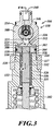
FIG. 3 illustrates a partial sectional view of an actuator 104 and engine valve 102 shown in FIG. 1.
FIGS. 4 through 6 illustrate a partial sectional view of actuator 104 in various stages of actuation along the line 4-4 shown in FIG. 3.
FIGS. 7 through 9 illustrate graphs of engine valve displacement over the angular position of the cam for a four-valve cylinder according to the present disclosure.
DETAILED DESCRIPTION
FIG. 1 illustrates a valve head 100 according to one aspect of the present teachings. The illustrated valve head 100 is configured to be mounted on an engine block of a diesel engine. However, the present teachings are not limited to diesel engines, and are applicable to other types of internal combustion engines such as those consuming gasoline, biofuels or other fuels. An engine block on which the valve head 100 can be mounted can contain piston bores. Pistons can be inserted into such bores to form combustion chambers. The valve head 100 can form the top portion of the combustion chambers when mounted on the engine block.
The illustrated valve head 100 is for use with six cylinders of a twelve cylinder engine. The twelve cylinder engine is a V-type engine having six cylinders on each side. However, the present teachings are applicable to other engine configurations as well, such as straight engine configurations, and different numbers of cylinders more or less than twelve. For example, the present teachings are applicable to engines having six, eight and ten cylinders.
The valve head 100 shown in FIG. 1 includes a hybrid valve actuation system wherein both mechanical and electrohydraulic actuation mechanisms are used to open and close the engine valves of a particular cylinder. When mounted on an engine block, the valve head 100 forms part of six combustion chambers. The head 100 includes twenty-four engine valves in total, four for each of the combustion chambers partially formed by the valve head. A feed rail 101 can be mounted at the top of valve head 100. The feed rail 101 has two high pressure conduits 103 that supply high pressure hydraulic fluid to the electrohydraulic actuators 104 discussed further herein, and a low pressure drain conduit 105 that allows hydraulic fluid to flow from the electrohydraulic actuators 104.
FIG. 2 illustrates a sectional view of the valve head 100 shown in FIG. 1. As seen in FIG. 2, two of the engine valves 102 corresponding to one of the cylinders are actuated by an electrohydraulic actuator 104. The other two engine valves 102 of the cylinder are mechanically actuated by cam 112 and rocker arms 114. The valve head 100 includes intake 106 and exhaust ports 108 through which air enters and combusted gas leaves the combustion chamber, respectively, during engine operation. The engine valves 102 actuated by electrohydraulic actuators 104 open and close respective passages from the combustion chamber to intake and exhaust ports 106, 108. Thus, one of the intake ports 106 for a particular cylinder is regulated by one of the electrohydraulic actuators 104 and one of the exhaust ports 108 is also regulated by one of the electrohydraulic actuators 104. For a particular cylinder, the entry and exit of gas from the combustion chamber is regulated in part by the valves 102 that are actuated mechanically and in part by valves 102 actuated by electrohydraulic actuators 104. When closed, the engine valves 102 are seated against valve seats 110.
Mechanical actuation of engine valves 102 shown in FIGS. 1 and 2 is achieved through a rotating cam 112 periodically transferring motion to a rocker arm 114, which in turn transfers linear motion to engine valves 102. Such mechanical actuation illustrates one possible type of mechanical valve actuation according to the present disclosure. Other forms of mechanical actuation may also be implemented to transform the rotational motion of a cam to kinetic energy or mechanical potential energy, and ultimately to translational motion of engine valves 102. Such mechanisms include a rotating cam placed in direct contact with an engine valve 102, or by including one or both of a lash adjuster and rocker arm between a cam and engine valve. Still other combinations of various valve train components are possible in order to achieve mechanical actuation of an engine valve. Such components include but are not limited to rocker arms, including deactivating rocker arms and variable lift rocker arms, pushrods, hydraulic lash adjusters and tappets.
FIG. 3 illustrates linear hydraulic actuator 104, which includes a two stage hydraulic piston 302. The two stage piston 302 has a large diameter piston member 304 partially disposed within a cavity 306 of an actuator housing 308. The large diameter piston member 304 has a cylindrically-shaped piston head 310 at one end 311 in fluid communication with hydraulic fluid that fills the volume 312. The volume 312 is formed in part by the housing 308, including the walls of the cavity 306, the upper surface 314 of the piston head 310 and the upper surface 316 of one end 311 of a small diameter piston 318. The piston head 310 has a cylindrical shape, and the cavity 306 has a size and shape that permits a close fit between the cavity 306 and piston 304, which in turn minimizes leaking of pressurized fluid from volume 312.
The small diameter piston member 318 is disposed within a tubular piston bore 320 in the large diameter piston member 304. Portions of the piston bore 320 have a shape complementary to the small diameter piston member 318. This complementary shape limits the motion of the small diameter piston member 318 with respect to the large diameter piston member 304. The small diameter piston member 318 has a cylindrically shaped outer surface 322 distal to the volume 312 relative to a frustoconical outer surface 328 of the small diameter piston member 318. The large diameter piston member 304 has a cylindrically shaped inner surface 323 that has a shape complimentary to the cylindrically shaped outer surface 322, and a frustoconical inner surface 332 that has a shape complimentary to the frustoconical outer surface 328. The complementary shapes limit the motion of the small diameter piston member 318 toward the volume 312.
The small diameter piston member 318 has another cylindrically shaped outer surface 324 proximal to the volume 312 relative to the frustoconical outer surface 328 of the small diameter piston member 318. The large diameter piston member 304 also has another cylindrically shaped inner surface 330 that has a shape complimentary to the cylindrically shaped outer surface 324 proximal to volume 312. The bore 320 is narrower at stop 317 than the diameter of the cylindrically shaped outer surface 324 of small diameter piston member 318. The stop 317 thus limits the downward motion of the small diameter piston member 304. The small diameter piston 318 includes a cap 333 and an insert 335. The insert 335 comes into contact with the engine valve 102, which contact causes the engine valve 102 to move in response to the motion of the piston 302. In other aspects of the present teachings, the insert 335 may be integrated into an engine valve 102.
According to one aspect of the present teachings, the actuator housing 308 of the hydraulic actuator 104 includes a valve housing 334 and a piston guide 336. In the illustrated actuator housing 308, the valve housing 334 is mounted above the piston guide 336. The piston 302 is partially inserted within the piston guide 336.
As shown in FIG. 4, the hydraulic actuator 104 includes a two position solenoid-based pressure valve 338. The pressure valve 338 includes a high pressure inlet 340, and low pressure outlets 342. The pressure valve 338 also includes volume inlet ports 344 that permit fluid to enter the volume 312 from the high pressure inlet 340, or allow fluid to exit the volume 312 through the low pressure outlets 342. During operation, the high pressure inlet 340 is in fluid communication with the high pressure fluid source, such as a high pressure feed conduit 103 of the feed rail 101 described above, while the low pressure outlets 342 are in fluid communication with the low pressure reservoir, such as the low pressure drain conduit 105 of the feed rail 101. An actuator valve, such as the illustrated spool valve member 346, regulates the flow of hydraulic fluid between the high pressure inlet 340, low pressure outlet 342, and volume inlet port 344. The spool valve member 346 includes a magnetic material that is responsive to magnetic fields generated by the coils 348 of a solenoid that can be activated to shift the position of the spool valve member 346. The spool valve member 346 controls whether pressurized fluid flows into volume 312, which in turn controls actuation of the engine valve 102 coupled to the piston 302.
FIGS. 4 through 6 illustrate the electrohydraulic actuator 104 in various stages of actuation. During operation, the solenoid coils 348 can generate a magnetic field caused by electrical current in the coils 348. In FIG. 4, the coils 348 are not conducting current, and the spool valve member 346 is biased to the closed position to the left side of the actuator 104. In this position, high pressure fluid is not permitted into volume 312, while fluid in the volume 312 can exit via volume inlet port 344 and low pressure outlet 342.
The spool valve member 346 has a plurality of channels 350 that wrap around the spool valve member 346. Depending on the position of the spool valve member 346, the channels 350 allow passage of hydraulic fluid between a high pressure inlet 340, low pressure outlets 342, and volume inlet ports 344. When the illustrated spool valve member 346 is in a low pressure position as illustrated in FIG. 4, it is shifted to the left within actuator housing 308. In this position, the volume 312 is in fluid communication with the low pressure outlet 342, which in turn is configured to be in fluid communication with a low pressure reservoir. In this position, fluid within the volume 312 is free to flow through the volume inlet ports 344 and the low pressure outlet 342.
FIG. 5 illustrates the electrohydraulic actuator 104 in a state where the solenoid coils 348 have been activated, shifting the spool valve member 346 to the right. This allows high pressure hydraulic fluid to travel from the high pressure inlet 340, through channels 350 of the spool valve member 346 and the volume inlet port 344, to the volume 312.
After the spool valve member 346 shifts to the right, high pressure fluid fills the volume 312. When high pressure fluid begins to fill the volume 312, the small diameter piston member 318 and large diameter piston member 304 initially move in unison. The end surface 316 of the small diameter member 318 and end surface 314 of the large diameter member 304 form a large surface area acted upon by the pressurized fluid. In some aspects, the surface area of the end surface 314 of the large diameter member 304 is about nine times larger than the surface area of the end surface 316 of the small diameter member 318. In other aspects of the present disclosure, the ratio of the surface area of the end surface 314 versus the end surface 316 can be between about eight to ten. The large surface area results in a greater force applied by the high pressure hydraulic fluid than would be applied to a piston having a smaller surface area in pressure communication with volume 312. This increased force can assist in overcoming the opposing force applied to the engine valves 102 as a result of the pressure differential between the combustion chamber and the exhaust or intake ports, which force can be substantial even when the pressure differential is small. As shown in FIG. 5, the piston head 310 of the large diameter piston member 304 is in contact with the guide 336, and thus the downward motion of the large diameter piston member 304 has stopped. However, the small diameter piston member is not inhibited by the large diameter piston member's 304 contact with the guide 336.
As shown in FIG. 6, as high pressure hydraulic fluid continues to enter the volume 312, the small diameter piston member 318 moves independently of the large diameter piston member 304 and continues to move downwardly. The small diameter piston member 318 can continue downwardly until the cap 333 makes contact with the stop 317. In one aspect of the present teachings, the engine valve 102 reaches a fully opened position when the cap 333 contacts the stop 317 and the large diameter piston member 304 has made contact with the guide 336.
When the valve member 346 returns to the left side of the actuator 104, allowing fluid to flow from the volume 312 to the low pressure outlets 342, the small diameter piston member 318 moves upwardly until the frustoconical inner surface 332 meets the frustoconical outer surface 328. The large diameter piston member 304 and the small diameter piston member 318 then move in unison. When the large diameter piston member 304 and the small diameter piston member 318 both move, a greater volume of hydraulic fluid is displaced for every unit of length the engine valve 102 moves relative to the volume displaced when only the small diameter piston member 318 is moving. This results in a greatly reduced seating velocity of the engine valve 102 because there is a greater pressure drop with a greater amount of displaced fluid. The rate of fluid flow will also depend on the size of high pressure inlet 340, low pressure outlets 342 and volume inlet port 344.
FIG. 7 illustrates engine valve lift for four engine valves of an engine cylinder measured in arbitrary standard units of length versus degrees of cam angular rotation. Line 700 corresponds to a cam-actuated exhaust valve and line 702 corresponds to a cam-actuated intake valve. Both of the engine valves represented by lines 700 and 702 are actuated at common points during the rotation of the cam. Lines 704 a, 704 b and 704 c correspond to the various points of actuation of the electrohydraulically actuated exhaust valves according to the present teachings. Line 704 a and 704 b represent two possible valve opening profiles of electrohydraulically driven exhaust valves opening earlier than the cam-actuated exhaust valve 700. This type of early opening of the exhaust valves can be referred to as early exhaust valve opening or “EEVO.” The electrohydraulically actuated exhaust valve can also follow the cam-actuated exhaust valve profile as shown by line 704 c.
The electrohydraulically driven intake valve 706 may also be controlled independently of the cam-actuated intake valve 702. As shown by curves 706 a and 706 b, the intake valves may be kept open longer than the corresponding cam-actuated intake valve 702. Such intake valve actuation can be referred to as late intake valve closing or “LIVC.” The electrohydraulically driven intake valve may also follow the cam-actuated intake valve profile as shown by line 706 c.
FIG. 8 illustrates engine valve lift for four valves of an engine cylinder exhibiting deactivation of the electrohydraulically actuated engine valves. The cam-actuated exhaust valve 800 and intake valve 802 operate normally, while the electrohydraulically actuated intake valves 804 and exhaust valves 806 are deactivated, and therefore stay closed. This engine valve management provides for greater velocity of the intake and exhaust gases. This can provide for improved swirl control, which can improve diffusion of fuel within the combustion chamber. In addition, deactivation of these valves reduces power consumed to generate the hydraulic pressure required to actuate the valves.
FIG. 9 illustrates another engine valve lift profile for four valves of an engine cylinder. The cam-actuated exhaust valve 900 and the electrohydraulically driven exhaust valve 902 open during common points in the cam cycle, for example between −120 degrees to 60 degrees. The cam-actuated intake valve 904 and the electrohydraulically driven intake valve 906 open during common points in the cam cycle. The electrohydraulically driven intake valve may close at various points after the cam-actuated intake valve is closed, or at the same time as the cam-actuated intake valve as shown by lines 906 a, 906 b and 906 c. The electrohydraulically driven exhaust valve may be opened while the intake valves are open, as shown by line 908. This recirculates the exhaust gas into the combustion chamber. Such cylinder engine valve management can be referred to as exhaust gas recirculation, or “EGR.” Engine braking may also be performed by the electrohydraulically actuated engine valves by opening the electrohydraulically actuated exhaust engine valve during a compression stroke as shown by line 910, thus removing energy from the cylinder.
The amount of displacement of the engine valves for can vary. Variable displacement of a particular valve 102 can be performed by a solenoid valve having two different actuation states, one effecting an engine valve displacement of a particular length and the second effecting an engine valve displacement of a different length. Such variation can also be achieved, for example, by including a second electrohydraulically actuated exhaust valve.
In some embodiments, the electrohydraulic actuator 104 can be utilized to provide variable displacement of a particular valve 102, such as between a closed position (FIG. 4), an intermediate lift position (FIG. 5), and a fully opened position (FIG. 6). For example only, the level of pressure of the high pressure fluid provided to the volume 312 can be varied to provide such variable valve lift. Varying the level of pressure of the high pressure fluid provided to the volume 312 can be performed, e.g., by the magnetic spool valve member 346, as well as by adjusting the pressure of the high pressure fluid provided to the high pressure inlet 340 directly.
When the level of pressure of the high pressure fluid is below a first threshold (such as by not providing high pressure fluid to the volume 312), the valve 102 can remain in the closed position shown in FIG. 4. For example only, the first threshold can correspond to a level of pressure of approximately 1,700 pounds per square inch. If the level of pressure of the high pressure fluid provided to the volume 312 is above the first threshold corresponding to the closed state, but below a second threshold, the valve 102 can be actuated to the intermediate lift position shown in FIG. 5. The intermediate lift position corresponds to a pressure sufficient to move the small diameter piston member 318 and large diameter piston member 304 in unison, but not separately. For example only, the second threshold can correspond to a level of pressure of approximately 2,000 pounds per square inch.
As described above, the end surface 316 of the small diameter member 318 and the end surface 314 of the large diameter member 304 form a large surface area acted upon by the high pressure fluid. This large, combined surface area results in a greater force applied by the high pressure fluid than would be applied to a piston having a smaller surface area in pressure communication with volume 312. Thus, the force applied to the large, combined surface area by the high pressure fluid may be sufficient to actuate the small diameter member 318 and the end surface 314 of the large diameter member 304 together, while remaining insufficient to provide the force necessary to actuate the small diameter member 318 by itself. The second threshold described above corresponds to the level of pressure at which the small diameter member 318 will move independently from the large diameter member 304.
In order to actuate the valve 102 to the fully opened position shown in FIG. 6, the level of pressure provided to the volume 312 can be above the second threshold. When the level of pressure of the high pressure fluid is above the second threshold, the force applied to the end surface 316 of the small diameter member 318 can be sufficient to move the small diameter member 318 independently from the large diameter member 304, as well as sufficient to move the small diameter piston member 318 and large diameter piston member 304 in unison.
By enabling an intermediate lift position, the electrohydraulic actuator 104 can provide an operating condition of the internal combustion engine in which one valve 102 (such as that mechanically actuated by a rotating cam) can be fully opened, while a second valve 102 (such as that actuated by the electrohydraulic actuator 104) can be actuated to the intermediate lift position. This may be particularly desirable for internal combustion engines that include two or more valves 102 for the intake ports 106 and/or the exhaust ports 108. The power consumption of the electrohydraulic actuator 104 can be proportional to the amount of valve lift. Thus, the power consumption of an internal combustion engine can be reduced by actuating a valve 102 that is actuated by the electrohydraulic actuator 104 to the intermediate lift position, while actuating the valve 102 that is mechanically actuated (e.g., by a rotating cam) to be fully opened, without noticeable loss of engine power and/or performance.
For the purposes of this disclosure and unless otherwise specified, “a” or “an” means “one or more.” To the extent that the term “includes” or “including” is used in the specification or the claims, it is intended to be inclusive in a manner similar to the term “comprising” as that term is interpreted when employed as a transitional word in a claim. Furthermore, to the extent that the term “or” is employed (e.g., A or B) it is intended to mean “A or B or both.” When the applicants intend to indicate “only A or B but not both” then the term “only A or B but not both” will be employed. Thus, use of the term “or” herein is the inclusive, and not the exclusive use. See, Bryan A. Garner, A Dictionary of Modern Legal Usage 624 (2d. Ed. 1995). Also, to the extent that the terms “in” or “into” are used in the specification or the claims, it is intended to additionally mean “on” or “onto.” As used herein, “about” will be understood by persons of ordinary skill in the art and will vary to some extent depending upon the context in which it is used. If there are uses of the term which are not clear to persons of ordinary skill in the art, given the context in which it is used, “about” will mean up to plus or minus 10% of the particular term. From about A to B is intended to mean from about A to about B, where A and B are the specified values.
While the present disclosure discusses various aspects in some detail, it is not the intention of the applicant to restrict or in any way limit the scope of the claimed invention to such detail. Additional advantages and modifications will be apparent to those skilled in the art. Therefore, the invention, in its broader aspects, is not limited to the specific details and illustrative examples shown and described. Accordingly, departures may be made from such details without departing from the spirit or scope of the applicant's claimed invention. Moreover, the foregoing teachings are illustrative, and no single feature or element is essential to all possible combinations that may be claimed in this or a later application.

Claims (19)

What is claimed is:
1. An engine valve actuation system for an internal combustion engine that includes an engine block, a cylinder head mounted to the engine block to form at least one combustion chamber and defining a first port and a second port, a first valve arranged at least partially within the first port and movable between an opened position and a closed position to selectively open the first port, a second valve arranged at least partially within the second port and movable between an opened position and a closed position to selectively open the second port, and a rotating cam mechanically coupled to the first valve to selectively move the first valve between the open and closed positions, the engine valve actuation system comprising:
a hydraulic valve actuator coupled to the second valve to selectively move the second valve between the open and closed positions, the hydraulic valve actuator comprising:
an actuator housing having a piston cavity, an inlet port, a high pressure port in fluid communication with a high pressure fluid conduit, and a low pressure port in fluid communication with a low pressure fluid conduit,
a piston disposed at least partially within the piston cavity and having a first surface at a first end in fluid communication with the inlet port, the first surface and actuator housing defining a volume, and
an actuator valve disposed within the actuator housing in fluid communication with the inlet port, the high pressure port, the low pressure port and the volume through the inlet port.
2. The engine valve actuation system of claim 1, wherein:
the actuator housing includes a solenoid;
the actuator valve includes a magnetic spool valve member responsive to the solenoid such that the magnetic spool valve member is positioned in one of a first position and second position when the solenoid is activated
the low pressure port is in fluid communication with a first spool channel of the spool valve member, the inlet port and the volume when the spool valve member is in the first position; and
the high pressure port is in fluid communication with a second spool channel of the spool valve member, the inlet port and the volume when the spool valve member is in the second position.
3. The engine valve actuation system of claim 2, wherein the piston includes a first member and a second member, the second member being slideably disposed within the first member, the first surface of the piston formed at least in part by a first member surface and a second member surface.
4. The engine valve actuation system of claim 3, wherein the first member has a flanged head portion at a first end of the first member, and wherein the first member surface is larger than the second member surface.
5. The engine valve actuation system of claim 4, wherein the surface area of the first member surface is between about 8 to about 10 times the surface area of the second member surface.
6. The engine valve actuation system of claim 4, wherein the flanged head portion has a cylindrical outer surface and the first member has a cylindrical inner surface forming a passage extending from the first end of the first member to a second end of the first member, the second member being at least partially disposed within the passage.
7. The engine valve actuation system of claim 6, wherein:
the cylindrical inner surface has a first cylindrically shaped surface having a first diameter, a frustoconical portion extending between the first cylindrically shaped inner surface and a second cylindrically shaped inner surface having a second diameter larger than the first diameter, the first cylindrically shaped surface being closer to the first end than the second cylindrically shaped surface; and
the second member has a first cylindrically shaped outer surface slideably engaged with the first cylindrically shaped inner surface, and a second cylindrically shaped outer surface slideably engaged with the second cylindrically shaped inner surface.
8. A hydraulic valve actuator configured to selectively actuate a valve of an internal combustion engine between an open and closed position, comprising:
an actuator housing having a piston cavity, an inlet port, a high pressure port in fluid communication with a high pressure fluid conduit, a low pressure port in fluid communication with a low pressure fluid conduit, and a solenoid;
a piston disposed at least partially within the piston cavity and having a first surface at a first end in fluid communication with the inlet port, the first surface and actuator housing defining a volume; and
an actuator valve disposed within the actuator housing in fluid communication with the inlet port, the high pressure port, the low pressure port and the volume through the inlet port, the actuator valve including a magnetic spool valve member responsive to the solenoid such that the magnetic spool valve member is positioned in one of a first position and second position when the solenoid is activated,
wherein the low pressure port is in fluid communication with a first spool channel of the magnetic spool valve member, the inlet port and the volume when the magnetic spool valve member is in the first position, and
wherein the high pressure port is in fluid communication with a second spool channel of the magnetic spool valve member, the inlet port and the volume when the magnetic spool valve member is in the second position.
9. The hydraulic valve actuator of claim 8, wherein the piston includes a first member and a second member, the second member being slideably disposed within the first member, the first surface of the piston formed at least in part by a first member surface and a second member surface.
10. The hydraulic valve actuator of claim 9, wherein the first member has a flanged head portion at a first end of the first member, and wherein the first member surface is larger than the second member surface.
11. The hydraulic valve actuator of claim 4, wherein the flanged head portion has a cylindrical outer surface and the first member has a cylindrical inner surface forming a passage extending from the first end of the first member to a second end of the first member, the second member being at least partially disposed within the passage.
12. The hydraulic valve actuator of claim 11, wherein:
the cylindrical inner surface has a first cylindrically shaped surface having a first diameter, a frustoconical portion extending between the first cylindrically shaped inner surface and a second cylindrically shaped inner surface having a second diameter larger than the first diameter, the first cylindrically shaped surface being closer to the first end than the second cylindrically shaped surface; and
the second member has a first cylindrically shaped outer surface slideably engaged with the first cylindrically shaped inner surface, and a second cylindrically shaped outer surface slideably engaged with the second cylindrically shaped inner surface.
13. An internal combustion engine, comprising:
an engine block;
a cylinder head mounted to the engine block to form at least one combustion chamber, the cylinder head defining a first intake port, a first exhaust port and a second port, the second port comprising one of an intake port and an exhaust port;
a first intake valve mounted to the cylinder head and arranged at least partially within the first intake port, the first intake valve being movable between an opened position and a closed position to selectively open and close the first intake port, respectively;
a first exhaust valve mounted to the cylinder head and arranged at least partially within the first exhaust port, the first exhaust valve being movable between an opened position and a closed position to selectively open and close the first exhaust port, respectively;
a second valve mounted to the cylinder head and arranged at least partially within the second port, the second valve being movable between an opened position and a closed position to selectively open and close the second port, respectively;
a rotating cam mechanically coupled to the first intake valve and the first exhaust valve, the rotating cam actuating the first intake valve and the first exhaust valve between the open and closed positions; and
a hydraulic valve actuator coupled to the second valve to selectively actuate the second valve between the open and closed positions, wherein the hydraulic valve actuator further comprises:
an actuator housing having a piston cavity, an inlet port, a high pressure port in fluid communication with a high pressure fluid conduit, and a low pressure port in fluid communication with a low pressure fluid conduit;
a piston disposed at least partially within the piston cavity and having a first surface at a first end in fluid communication with the inlet port, the first surface and actuator housing defining a volume; and,
an actuator valve disposed within the actuator housing in fluid communication with the inlet port, the high pressure port, the low pressure port and the volume through the inlet port.
14. The internal combustion engine of claim 13, wherein:
the actuator housing includes a solenoid;
the actuator valve includes a magnetic spool valve member responsive to the solenoid such that the magnetic spool valve member is positioned in one of a first position and second position when the solenoid is activated
the low pressure port is in fluid communication with a first spool channel of the spool valve member, the inlet port and the volume when the spool valve member is in the first position; and
the high pressure port is in fluid communication with a second spool channel of the spool valve member, the inlet port and the volume when the spool valve member is in the second position.
15. The internal combustion engine of claim 13, wherein the piston includes a first member and a second member, the second member being slideably disposed within the first member, the first surface of the piston formed at least in part by a first member surface and a second member surface.
16. The internal combustion engine of claim 15, wherein the first member has a flanged head portion at a first end of the first member, and wherein the first member surface is larger than the second member surface.
17. The internal combustion engine of claim 16, wherein the surface area of the first member surface is between about 8 to about 10 times the surface area of the second member surface.
18. The internal combustion engine of claim 16, wherein the flanged head portion has a cylindrical outer surface and the first member has a cylindrical inner surface forming a passage extending from the first end of the first member to a second end of the first member, the second member being at least partially disposed within the passage.
19. The internal combustion engine of claim 18, wherein:
the cylindrical inner surface has a first cylindrically shaped surface having a first diameter, a frustoconical portion extending between the first cylindrically shaped inner surface and a second cylindrically shaped inner surface having a second diameter larger than the first diameter, the first cylindrically shaped surface being closer to the first end than the second cylindrically shaped surface; and
the second member has a first cylindrically shaped outer surface slideably engaged with the first cylindrically shaped inner surface, and a second cylindrically shaped outer surface slideably engaged with the second cylindrically shaped inner surface.
US14/045,490 2012-10-05 2013-10-03 Hybrid cam-camless variable valve actuation system Expired - Fee Related US9157339B2 (en)

Priority Applications (7)

Application Number Priority Date Filing Date Title
US14/045,490 US9157339B2 (en) 2012-10-05 2013-10-03 Hybrid cam-camless variable valve actuation system
CN201380051996.2A CN104704210B (en) 2012-10-05 2013-10-04 Hybrid cam-camless variable valve actuation system
PCT/US2013/063376 WO2014055821A1 (en) 2012-10-05 2013-10-04 Hybrid cam-camless variable valve actuation system
EP13785978.1A EP2904224B1 (en) 2012-10-05 2013-10-04 Hybrid cam-camless variable valve actuation system
KR1020157011446A KR20150063542A (en) 2012-10-05 2013-10-04 Hybrid cam-camless variable valve actuation system
JP2015535803A JP6272334B2 (en) 2012-10-05 2013-10-04 Hybrid cam-camless variable valve drive system
JP2017220010A JP2018048644A (en) 2012-10-05 2017-11-15 Hybrid cam-camless variable valve drive system

Applications Claiming Priority (4)

Application Number Priority Date Filing Date Title
US201261710428P 2012-10-05 2012-10-05
US201261715256P 2012-10-17 2012-10-17
US201261715255P 2012-10-17 2012-10-17
US14/045,490 US9157339B2 (en) 2012-10-05 2013-10-03 Hybrid cam-camless variable valve actuation system

Publications (2)

Publication Number Publication Date
US20140116363A1 US20140116363A1 (en) 2014-05-01
US9157339B2 true US9157339B2 (en) 2015-10-13

Family

ID=49517632

Family Applications (1)

Application Number Title Priority Date Filing Date
US14/045,490 Expired - Fee Related US9157339B2 (en) 2012-10-05 2013-10-03 Hybrid cam-camless variable valve actuation system

Country Status (6)

Country Link
US (1) US9157339B2 (en)
EP (1) EP2904224B1 (en)
JP (2) JP6272334B2 (en)
KR (1) KR20150063542A (en)
CN (1) CN104704210B (en)
WO (1) WO2014055821A1 (en)

Cited By (4)

* Cited by examiner, † Cited by third party
Publication number Priority date Publication date Assignee Title
WO2018035302A1 (en) 2016-08-17 2018-02-22 Eaton Corporation Friction mitigation in cylinder deactivation
US10526934B2 (en) * 2015-09-25 2020-01-07 Eaton Intelligent Power Limited Cylinder deactivation control and methods
US11187162B2 (en) 2016-08-17 2021-11-30 Eaton Intelligent Power Limited Extended coast and controlled deceleration using cylinder deactivation
US11326533B2 (en) 2016-01-19 2022-05-10 Eaton Intelligent Power Limited Cylinder deactivation and engine braking for thermal management

Families Citing this family (7)

* Cited by examiner, † Cited by third party
Publication number Priority date Publication date Assignee Title
WO2014123755A2 (en) * 2013-01-31 2014-08-14 Eaton Corporation Centrifugal process to eliminate air in high pressure chamber of hydraulic lash adjuster
WO2016118482A1 (en) 2015-01-19 2016-07-28 Eaton Corporation Method and system for diesel cylinder deactivation
WO2018085517A2 (en) * 2016-11-02 2018-05-11 Eaton Corporation Cam-camless cylinder head and systems
DE102018117234A1 (en) * 2018-07-17 2020-01-23 Schaeffler Technologies AG & Co. KG Module for a variable stroke valve train of an internal combustion engine
DE102018122787A1 (en) * 2018-09-18 2020-03-19 Schaeffler Technologies AG & Co. KG Module for a variable stroke valve train of an internal combustion engine
CN114729579B (en) * 2019-11-27 2024-03-12 比亚乔公司 Camshaft with phasing device for multi-cylinder internal combustion engines with lift valve
US12209544B1 (en) 2023-11-29 2025-01-28 Eaton Intelligent Power Limited Engine braking in hydrogen internal combustion engines

Citations (12)

* Cited by examiner, † Cited by third party
Publication number Priority date Publication date Assignee Title
US5248123A (en) 1991-12-11 1993-09-28 North American Philips Corporation Pilot operated hydraulic valve actuator
US5456222A (en) 1995-01-06 1995-10-10 Ford Motor Company Spool valve control of an electrohydraulic camless valvetrain
WO1996039572A1 (en) 1995-06-06 1996-12-12 Caterpillar Inc. Engine compression braking apparatus and method
US5713316A (en) 1995-05-17 1998-02-03 Sturman; Oded E. Hydraulic actuator for an internal combustion engine
JP2000282823A (en) 1999-03-30 2000-10-10 Mitsubishi Heavy Ind Ltd Hydraulic exhaust valve drive unit
US20020162524A1 (en) 1998-09-09 2002-11-07 Ojeda William De Unit trigger actuator
US20030164163A1 (en) 2002-03-01 2003-09-04 Ning Lei Method and apparatus for flexibly regulating internal combustion engine valve flow
US20040040530A1 (en) 2002-08-27 2004-03-04 Toyota Jidosha Kabushiki Kaisha Internal combustion engine
GB2394000A (en) 2002-10-10 2004-04-14 Lotus Car Arrangement of an i.c. engine poppet valve and hydraulic actuator
EP1464794A2 (en) 2003-04-02 2004-10-06 General Motors Corporation Engine valve actuator assembly with dual hydraulic feedback
US20080091329A1 (en) 2006-10-11 2008-04-17 Pierre Duret Internal-combustion engine control method and engine using same
US20100191442A1 (en) 2009-01-23 2010-07-29 Turbo Innovation, Llc Internal combustion engine cycle

Family Cites Families (8)

* Cited by examiner, † Cited by third party
Publication number Priority date Publication date Assignee Title
JPS4915163B1 (en) * 1972-07-14 1974-04-12
JP2645482B2 (en) * 1987-09-09 1997-08-25 株式会社日本自動車部品総合研究所 Hydraulic drive valve device for internal combustion engine
JPS6449606U (en) * 1987-09-24 1989-03-28
JPH03253710A (en) * 1990-03-01 1991-11-12 Nippon Soken Inc Hydraulic drive valve device for internal combustion engine
JP2685963B2 (en) * 1990-06-05 1997-12-08 株式会社日本自動車部品総合研究所 Valve drive for internal combustion engine
JPH04171208A (en) * 1990-11-02 1992-06-18 Nippon Soken Inc Hydraulic operated valve device
US5682846A (en) * 1996-12-19 1997-11-04 Eaton Corporation Engine valve actuator with differential area pistons
JP5446706B2 (en) * 2009-10-13 2014-03-19 いすゞ自動車株式会社 Internal combustion engine control method and internal combustion engine

Patent Citations (13)

* Cited by examiner, † Cited by third party
Publication number Priority date Publication date Assignee Title
US5248123A (en) 1991-12-11 1993-09-28 North American Philips Corporation Pilot operated hydraulic valve actuator
US5647318A (en) * 1994-07-29 1997-07-15 Caterpillar Inc. Engine compression braking apparatus and method
US5456222A (en) 1995-01-06 1995-10-10 Ford Motor Company Spool valve control of an electrohydraulic camless valvetrain
US5713316A (en) 1995-05-17 1998-02-03 Sturman; Oded E. Hydraulic actuator for an internal combustion engine
WO1996039572A1 (en) 1995-06-06 1996-12-12 Caterpillar Inc. Engine compression braking apparatus and method
US20020162524A1 (en) 1998-09-09 2002-11-07 Ojeda William De Unit trigger actuator
JP2000282823A (en) 1999-03-30 2000-10-10 Mitsubishi Heavy Ind Ltd Hydraulic exhaust valve drive unit
US20030164163A1 (en) 2002-03-01 2003-09-04 Ning Lei Method and apparatus for flexibly regulating internal combustion engine valve flow
US20040040530A1 (en) 2002-08-27 2004-03-04 Toyota Jidosha Kabushiki Kaisha Internal combustion engine
GB2394000A (en) 2002-10-10 2004-04-14 Lotus Car Arrangement of an i.c. engine poppet valve and hydraulic actuator
EP1464794A2 (en) 2003-04-02 2004-10-06 General Motors Corporation Engine valve actuator assembly with dual hydraulic feedback
US20080091329A1 (en) 2006-10-11 2008-04-17 Pierre Duret Internal-combustion engine control method and engine using same
US20100191442A1 (en) 2009-01-23 2010-07-29 Turbo Innovation, Llc Internal combustion engine cycle

Non-Patent Citations (1)

* Cited by examiner, † Cited by third party
Title
International Search Report and Written Opinion for International Application No. PCT/US2013-063376 dated Mar. 4, 2014.

Cited By (9)

* Cited by examiner, † Cited by third party
Publication number Priority date Publication date Assignee Title
US10526934B2 (en) * 2015-09-25 2020-01-07 Eaton Intelligent Power Limited Cylinder deactivation control and methods
US10563549B2 (en) 2015-09-25 2020-02-18 Eaton Intelligent Power Limited Cylinder deactivation control and methods
US10619525B2 (en) 2015-09-25 2020-04-14 Eaton Intelligent Power Limited Cylinder deactivation hydraulic lash adjuster
US11459917B2 (en) 2015-09-25 2022-10-04 Eaton Intelligent Power Limited Cylinder deactivation energy waste management
US11326533B2 (en) 2016-01-19 2022-05-10 Eaton Intelligent Power Limited Cylinder deactivation and engine braking for thermal management
WO2018035302A1 (en) 2016-08-17 2018-02-22 Eaton Corporation Friction mitigation in cylinder deactivation
US11187162B2 (en) 2016-08-17 2021-11-30 Eaton Intelligent Power Limited Extended coast and controlled deceleration using cylinder deactivation
US11578673B2 (en) 2016-08-17 2023-02-14 Eaton Intelligent Power Limited Transmission control with cylinder deactivation
US11578672B2 (en) 2016-08-17 2023-02-14 Eaton Intelligent Power Limited Friction mitigation in cylinder deactivation

Also Published As

Publication number Publication date
EP2904224B1 (en) 2017-11-22
JP6272334B2 (en) 2018-01-31
WO2014055821A1 (en) 2014-04-10
JP2015533988A (en) 2015-11-26
CN104704210B (en) 2017-10-27
EP2904224A1 (en) 2015-08-12
KR20150063542A (en) 2015-06-09
CN104704210A (en) 2015-06-10
JP2018048644A (en) 2018-03-29
US20140116363A1 (en) 2014-05-01

Similar Documents

Publication Publication Date Title
US9157339B2 (en) Hybrid cam-camless variable valve actuation system
EP2715076B1 (en) Primary and auxiliary rocker arm assembly for engine valve actuation
US8230830B2 (en) Electronically controlled hydraulic system for variable actuation of the valves of an internal combustion engine, with fast filling of the high pressure side of the system
US7559300B2 (en) Multiple slave piston valve actuation system
FI121512B (en) Piston engine suction valve control arrangement
US20040050352A1 (en) Variable valve train for a cam-activated lifting valve of an internal combustion engine
EP1338764B1 (en) A multicylinder internal-combustion engine with electronically controlled hydraulic device for controlling variable actuation of the valves, integrated in a pre-assembled unit mounted on the engine cylinder head
US7171932B2 (en) Internal-combustion engine having an electronically controlled hydraulic device for variably actuating intake valves
US6886510B2 (en) Engine valve actuator assembly with dual hydraulic feedback
CN118251540A (en) Multi-cylinder internal combustion engine, the cylinders of which are equipped with an intake valve variable actuation system with interdigitated hydraulic circuits
US20120042840A1 (en) Electro-hydraulic variable valve lift apparatus
US20050188966A1 (en) System and method for multi-lift valve actuation
US20130146002A1 (en) Electro-hydraulic variable valve lift system
JP4028742B2 (en) Internal combustion engine
US20070256651A1 (en) Valve actuator assembly having a center biased spool valve with detent feature
JP4009477B2 (en) Improvement of internal combustion engine with hydraulic system for variable operation of engine valve
US20040065285A1 (en) Variable engine valve actuator
WO2018085517A2 (en) Cam-camless cylinder head and systems
CN113756905A (en) System and method for hydraulic lash adjuster oil flow
CN204357518U (en) Actuator and electro-hydraulic actuation formula engine valve
DE102024121230B3 (en) Variable displacement valve control systems with rocker arm shaft porting and insert sleeves for engine cylinder deactivation
US20040194741A1 (en) Engine valve actuator assembly with hydraulic feedback
EP2834482B1 (en) Gas exchange valve arrangement and valve
CN1922391A (en) Valve deactivation device
JPS61261614A (en) Oil feeder of tappet mechanism equipped with hydraulic tappet for internal-combustion engine

Legal Events

Date Code Title Description
AS Assignment

Owner name: EATON CORPORATION, OHIO

Free format text: ASSIGNMENT OF ASSIGNORS INTEREST;ASSIGNORS:STRETCH, DALE ARDEN;GENISE, DAVID GERARD;NIELSEN, DOUGLAS JOHN;AND OTHERS;SIGNING DATES FROM 20131021 TO 20140108;REEL/FRAME:031929/0412

STCF Information on status: patent grant

Free format text: PATENTED CASE

MAFP Maintenance fee payment

Free format text: PAYMENT OF MAINTENANCE FEE, 4TH YEAR, LARGE ENTITY (ORIGINAL EVENT CODE: M1551); ENTITY STATUS OF PATENT OWNER: LARGE ENTITY

Year of fee payment: 4

AS Assignment

Owner name: EATON INTELLIGENT POWER LIMITED, IRELAND

Free format text: ASSIGNMENT OF ASSIGNORS INTEREST;ASSIGNOR:EATON CORPORATION;REEL/FRAME:048855/0626

Effective date: 20171231

FEPP Fee payment procedure

Free format text: MAINTENANCE FEE REMINDER MAILED (ORIGINAL EVENT CODE: REM.); ENTITY STATUS OF PATENT OWNER: LARGE ENTITY

LAPS Lapse for failure to pay maintenance fees

Free format text: PATENT EXPIRED FOR FAILURE TO PAY MAINTENANCE FEES (ORIGINAL EVENT CODE: EXP.); ENTITY STATUS OF PATENT OWNER: LARGE ENTITY

STCH Information on status: patent discontinuation

Free format text: PATENT EXPIRED DUE TO NONPAYMENT OF MAINTENANCE FEES UNDER 37 CFR 1.362

FP Lapsed due to failure to pay maintenance fee

Effective date: 20231013