US9154897B2 - Immersive audio rendering system - Google Patents
Immersive audio rendering system Download PDFInfo
- Publication number
- US9154897B2 US9154897B2 US13/342,758 US201213342758A US9154897B2 US 9154897 B2 US9154897 B2 US 9154897B2 US 201213342758 A US201213342758 A US 201213342758A US 9154897 B2 US9154897 B2 US 9154897B2
- Authority
- US
- United States
- Prior art keywords
- depth
- signal
- audio signals
- signals
- audio
- Prior art date
- Legal status (The legal status is an assumption and is not a legal conclusion. Google has not performed a legal analysis and makes no representation as to the accuracy of the status listed.)
- Active, expires
Links
Images


Classifications
-
- H—ELECTRICITY
- H04—ELECTRIC COMMUNICATION TECHNIQUE
- H04S—STEREOPHONIC SYSTEMS
- H04S1/00—Two-channel systems
- H04S1/002—Non-adaptive circuits, e.g. manually adjustable or static, for enhancing the sound image or the spatial distribution
-
- H—ELECTRICITY
- H04—ELECTRIC COMMUNICATION TECHNIQUE
- H04R—LOUDSPEAKERS, MICROPHONES, GRAMOPHONE PICK-UPS OR LIKE ACOUSTIC ELECTROMECHANICAL TRANSDUCERS; DEAF-AID SETS; PUBLIC ADDRESS SYSTEMS
- H04R5/00—Stereophonic arrangements
-
- H—ELECTRICITY
- H04—ELECTRIC COMMUNICATION TECHNIQUE
- H04S—STEREOPHONIC SYSTEMS
- H04S7/00—Indicating arrangements; Control arrangements, e.g. balance control
- H04S7/30—Control circuits for electronic adaptation of the sound field
-
- H—ELECTRICITY
- H04—ELECTRIC COMMUNICATION TECHNIQUE
- H04S—STEREOPHONIC SYSTEMS
- H04S7/00—Indicating arrangements; Control arrangements, e.g. balance control
- H04S7/30—Control circuits for electronic adaptation of the sound field
- H04S7/302—Electronic adaptation of stereophonic sound system to listener position or orientation
-
- H—ELECTRICITY
- H04—ELECTRIC COMMUNICATION TECHNIQUE
- H04S—STEREOPHONIC SYSTEMS
- H04S2400/00—Details of stereophonic systems covered by H04S but not provided for in its groups
- H04S2400/01—Multi-channel, i.e. more than two input channels, sound reproduction with two speakers wherein the multi-channel information is substantially preserved
-
- H—ELECTRICITY
- H04—ELECTRIC COMMUNICATION TECHNIQUE
- H04S—STEREOPHONIC SYSTEMS
- H04S2400/00—Details of stereophonic systems covered by H04S but not provided for in its groups
- H04S2400/07—Generation or adaptation of the Low Frequency Effect [LFE] channel, e.g. distribution or signal processing
-
- H—ELECTRICITY
- H04—ELECTRIC COMMUNICATION TECHNIQUE
- H04S—STEREOPHONIC SYSTEMS
- H04S2400/00—Details of stereophonic systems covered by H04S but not provided for in its groups
- H04S2400/11—Positioning of individual sound objects, e.g. moving airplane, within a sound field
-
- H—ELECTRICITY
- H04—ELECTRIC COMMUNICATION TECHNIQUE
- H04S—STEREOPHONIC SYSTEMS
- H04S2420/00—Techniques used stereophonic systems covered by H04S but not provided for in its groups
- H04S2420/01—Enhancing the perception of the sound image or of the spatial distribution using head related transfer functions [HRTF's] or equivalents thereof, e.g. interaural time difference [ITD] or interaural level difference [ILD]
Definitions
- Audio systems have developed beyond the simpler stereo systems having separate left and right recording/playback channels to what are commonly referred to as surround sound systems.
- Surround sound systems are generally designed to provide a more realistic playback experience for the listener by providing sound sources that originate or appear to originate from a plurality of spatial locations arranged about the listener, generally including sound sources located behind the listener.
- a surround sound system will frequently include a center channel, at least one left channel, and at least one right channel adapted to generate sound generally in front of the listener.
- Surround sound systems will also generally include at least one left surround source and at least one right surround source adapted for generation of sound generally behind the listener.
- Surround sound systems can also include a low frequency effects (LFE) channel, sometimes referred to as a subwoofer channel, to improve the playback of low frequency sounds.
- LFE low frequency effects
- a surround sound system having a center channel, a left front channel, a right front channel, a left surround channel, a right surround channel, and an LFE channel can be referred to as a 5.1 surround system.
- the number 5 before the period indicates the number of non-bass speakers present and the number 1 after the period indicates the presence of a subwoofer.
- a method of rendering depth in an audio output signal includes receiving a plurality of audio signals, identifying first depth steering information from the audio signals at a first time, and identifying subsequent depth steering information from the audio signals at a second time.
- the method can include decorrelating, by one or more processors, the plurality of audio signals by a first amount that depends at least partly on the first depth steering information to produce first decorrelated audio signals.
- the method may further include outputting the first decorrelated audio signals for playback to a listener.
- the method can include, subsequent to said outputting, decorrelating the plurality of audio signals by a second amount different from the first amount, where the second amount can depend at least partly on the subsequent depth steering information to produce second decorrelated audio signals.
- the method can include outputting the second decorrelated audio signals for playback to the listener.
- a method of rendering depth in an audio output signal can include receiving a plurality of audio signals, identifying depth steering information that changes over time, decorrelating the plurality of audio signals dynamically over time, based at least partly on the depth steering information, to produce a plurality of decorrelated audio signals, and outputting the plurality of decorrelated audio signals for playback to a listener.
- At least said decorrelating or any other subset of the method can be implemented by electronic hardware.
- a system for rendering depth in an audio output signal can include, in some embodiments: a depth estimator that can receive two or more audio signals and that can identify depth information associated with the two or more audio signals, and a depth renderer comprising one or more processors.
- the depth renderer can decorrelate the two or more audio signals dynamically over time based at least partly on the depth information to produce a plurality of decorrelated audio signals, and output the plurality of decorrelated audio signals (e.g., for playback to a listener and/or output to another audio processing component).
- Various embodiments of a method of rendering depth in an audio output signal include receiving input audio having two or more audio signals, estimating depth information associated with the input audio, which depth information may change over time, and enhancing the audio dynamically based on the estimated depth information by one or more processors. This enhancing can vary dynamically based on variations in the depth information over time. Further, the method can include outputting the enhanced audio.
- a system for rendering depth in an audio output signal can include, in several embodiments, a depth estimator that can receive input audio having two or more audio signals and that can estimate depth information associated with the input audio; and an enhancement component having one or more processors.
- the enhancement component can enhance the audio dynamically based on the estimated depth information. This enhancement can vary dynamically based on variations in the depth information over time.
- a method of modulating a perspective enhancement applied to an audio signal includes receiving left and right audio signals, where the left and right audio signals each have information about a spatial position of a sound source relative to a listener.
- the method can also include calculating difference information in the left and right audio signals, applying at least one perspective filter to the difference information in the left and right audio signals to yield left and right output signals, and applying a gain to the left and right output signals.
- a value of this gain can be based at least in part on the calculated difference information.
- At least said applying the gain (or the entire method or a subset thereof) is performed by one or more processors.
- a system for modulating a perspective enhancement applied to an audio signal includes a signal analysis component that can analyze a plurality of audio signals by at least: receive left and right audio signals, where the left and right audio signals each have information about a spatial position of a sound source relative to a listener, and obtain a difference signal from the left and right audio signals.
- the system can also include a surround processor having one or more physical processors.
- the surround processor can apply at least one perspective filter to the difference signal to yield left and right output signals, where an output of the at least one perspective filter can be modulated based at least in part on the calculated difference information.
- non-transitory physical computer storage having instructions stored therein can implement, in one or more processors, operations for modulating a perspective enhancement applied to an audio signal. These operations can include: receiving left and right audio signals, where the left and right audio signals each have information about a spatial position of a sound source relative to a listener, calculating difference information in the left and right audio signals, applying at least one perspective filter to each of the left and right audio signals to yield left and right output signals, and modulating said application of the at least one perspective filter based at least in part on the calculated difference information.
- a system for modulating a perspective enhancement applied to an audio signal includes, in certain embodiments, means for receiving left and right audio signals, where the left and right audio signals each have information about a spatial position of a sound source relative to a listener, means for calculating difference information in the left and right audio signals, means for applying at least one perspective filter to each of the left and right audio signals to yield left and right output signals, and means for modulating said application of the at least one perspective filter based at least in part on the calculated difference information.
- FIG. 1A illustrates an example depth rendering scenario that employs an embodiment of a depth processing system.
- FIGS. 1B , 2 A, and 2 B illustrate aspects of a listening environment relevant to embodiments of depth rendering algorithms.
- FIGS. 3A through 3D illustrate example embodiments of the depth processing system of FIG. 1 .
- FIG. 3E illustrates an embodiment of a crosstalk canceller that can be included in any of the depth processing systems described herein.
- FIG. 4 illustrates an embodiment of a depth rendering process that can be implemented by any of the depth processing systems described herein.
- FIG. 5 illustrates an embodiment of a depth estimator.
- FIGS. 6A and 6B illustrate embodiments of depth renderers.
- FIGS. 7A , 7 B, 8 A, and 8 B illustrate example pole-zero and phase-delay plots associated with the example depth renderers depicted in FIGS. 6A and 6B .
- FIG. 9 illustrates an example frequency-domain depth estimation process.
- FIGS. 10A and 10B illustrate examples of video frames that can be used to estimate depth.
- FIG. 11 illustrates an embodiment of a depth estimation and rendering algorithm that can be used to estimate depth from video data.
- FIG. 12 illustrates an example analysis of depth based on video data.
- FIGS. 13 and 14 illustrate embodiments of surround processors.
- FIGS. 15 and 16 illustrate embodiments of perspective curves that can be used by the surround processors to create a virtual surround effect.
- Surround sound systems attempt to create immersive audio environments by projecting sound from multiple speakers situated around a listener. Surround sound systems are typically preferred by audio enthusiasts over systems with fewer speakers, such as stereo systems. However, stereo systems are often cheaper by virtue of having fewer speakers, and thus, many attempts have been made to approximate the surround sound effect with stereo speakers. Despite such attempts, surround sound environments with more than two speakers are often more immersive than stereo systems.
- This disclosure describes a depth processing system that employs stereo speakers to achieve immersive effects, among possibly other speaker configurations.
- the depth processing system can advantageously manipulate phase and/or amplitude information to render audio along a listener's median plane, thereby rendering audio at varying depths with respect to a listener.
- the depth processing system analyzes left and right stereo input signals to infer depth, which may change over time. The depth processing system can then vary the phase and/or amplitude decorrelation between the audio signals over time, thereby creating an immersive depth effect.
- the features of the audio systems described herein can be implemented in electronic devices, such as phones, televisions, laptops, other computers, portable media players, car stereo systems, and the like to create an immersive audio effect using two or more speakers.
- FIG. 1A illustrates an embodiment of an immersive audio environment 100 .
- the immersive audio environment 100 shown includes a depth processing system 110 that receives two (or more) channel audio inputs and produces two channel audio outputs to left and right speakers 112 , 114 , with an optional third output to a subwoofer 116 .
- the depth processing system 110 analyzes the two-channel audio input signals to estimate or infer depth information about those signals. Using this depth information, the depth processing system 110 can adjust the audio input signals to create a sense of depth in the audio output signals provided to the left and right stereo speakers 112 , 114 .
- the left and right speakers can output an immersive sound field (shown by curved lines) for a listener 102 . This immersive sound field can create a sense of depth for the listener 102 .
- the immersive sound field effect provided by the depth processing system 110 can function more effectively than the immersive effects of surround sound speakers.
- the depth processing system 110 can provide benefits over existing surround systems.
- One advantage provided in certain embodiments is that the immersive sound field effect can be relatively sweet-spot independent, providing an immersive effect throughout the listening space.
- a heightened immersive effect can be achieved by placing the listener 102 approximately equidistant between the speakers and at an angle forming a substantially equilateral triangle with the two speakers (shown by dashed lines 104 ).
- FIG. 1B illustrates aspects of a listening environment 150 relevant to embodiments of depth rendering. Shown is a listener 102 in the context of two geometric planes 160 , 170 associated with the listener 102 . These planes include a median or saggital plane 160 and a frontal or coronal plane 170 . A three-dimensional audio effect can beneficially be obtained in some embodiments by rendering audio along the listener's 102 median plane.
- An example coordinate system 180 is shown next to the listener 102 for reference.
- the median plane 160 lies in the y-z plane
- the coronal plane 170 lies in the x-y plane.
- the x-y plane also corresponds to a plane that may be formed between two stereo speakers facing the listener 102 .
- the z-axis of the coordinate system 180 can be a normal line to such a plane.
- Rendering audio along the median plane 160 can be thought of in some implementations as rendering audio along the z-axis of the coordinate system 180 .
- a depth effect can be rendered by the depth processing system 110 along the median plane, such that some sounds sound closer to the listener along the median plane 160 , and some sound farther from the listener 102 along the median plane 160 .
- the depth processing system 110 can also render sounds along both the median and coronal planes 160 , 170 .
- the ability to render in three dimensions in some embodiments can increase the listener's 102 sense of immersion in the audio scene and can also heighten the illusion of three-dimensional video when experienced together.
- a listener's perception of depth can be visualized by the example sound source scenarios 200 depicted in FIGS. 2A and 2B .
- a sound source 252 is positioned at a distance from a listener 202 , whereas the sound source 252 is relatively closer to the listener 202 in FIG. 2B .
- a sound source is typically perceived by both ears, with the ear closer to the sound source 252 typically hearing the sound before the other ear.
- the delay in sound reception from one ear to the other can be considered an interaural time delay (ITD).
- IID interaural intensity difference
- IID interaural intensity difference
- Lines 272 , 274 drawn from the sound source 252 to each ear of the listener 202 in FIGS. 2A and 2B form an included angle. This angle is smaller at a distance and larger when the sound source 252 is closer, as shown in FIGS. 2A and 2B . The farther away a sound source 252 is from the listener 202 , the more the sound source 252 approximates a point source with a 0 degree included angle.
- left and right audio signals may be relatively in-phase to represent a distant sound source 252 , and these signals may be relatively out of phase to represent a closer sound source 252 (assuming a non-zero azimuthal arrival angle with respect to the listener 102 , such that the sound source 252 is not directly in front of the listener). Accordingly, the ITD and IID of a distant source 252 may be relatively smaller than the ITD and IID of a closer source 252 .
- Stereo recordings can include information that can be analyzed to infer depth of a sound source 252 with respect to a listener 102 .
- ITD and IID information between left and right stereo channels can be represented as phase and/or amplitude decorrelation between the two channels. The more decorrelated the two channels are, the more spacious the sound field may be, and vice versa.
- the depth processing system 110 can advantageously manipulate this phase and/or amplitude decorrelation to render audio along the listener's 102 median plane 160 , thereby rendering audio along varying depths.
- the depth processing system 110 analyzes left and right stereo input signals to infer depth, which may change over time. The depth processing system 110 can then vary the phase and/or amplitude decorrelation between the input signals over time to create this sense of depth.
- FIGS. 3A through 3D illustrate more detailed embodiments of depth processing systems 310 .
- FIG. 3A illustrates a depth processing system 310 A that renders a depth effect based on stereo and/or video inputs.
- FIG. 3B illustrates a depth processing system 310 B that creates a depth effect based on surround sound and/or video inputs.
- FIG. 3C a depth processing system 310 C creates a depth effect using audio object information.
- FIG. 3D is similar to FIG. 3A , except that an additional crosstalk cancellation component is provided.
- Each of these depth processing systems 310 can implement the features of the depth processing system 110 described above. Further, each of the components shown can be implemented in hardware and/or software.
- the depth processing system 310 A receives left and right input signals, which are provided to a depth estimator 320 a .
- the depth estimator 320 a is an example of a signal analysis component that can analyze the two signals to estimate depth of the audio represented by the two signals.
- the depth estimator 320 a can generate depth control signals based on this depth estimate, which a depth renderer 330 a can use to emphasize phase and/or amplitude decorrelation (e.g., ITD and IID differences) between the two channels.
- the depth-rendered output signals are provided to an optional surround processing module 340 a in the depicted embodiment, which can optionally broaden the sound stage and thereby increase the sense of depth.
- the depth estimator 320 a analyzes difference information in the left and right input signals, for example, by calculating an L ⁇ R signal.
- the magnitude of the L ⁇ R signal can reflect depth information in the two input signals.
- the L and R signals can become more out-of-phase as a sound moves closer to a listener.
- larger magnitudes in the L ⁇ R signal can reflect closer signals than smaller magnitudes of the L ⁇ R signal.
- the depth estimator 320 a can also analyze the separate left and right signals to determine which of the two signals is dominant. Dominance in one signal can provide clues as to how to adjust ITD and/or IID differences to emphasize the dominant channel and thereby emphasize depth. Thus, in some embodiments, the depth estimator 320 a creates some or all of the following control signals: L ⁇ R, L, R, and also optionally L+R. The depth estimator 320 a can use these control signals to adjust filter characteristics applied by the depth renderer 330 a (described below).
- the depth estimator 320 a can also determine depth information based on video information instead of or in addition to the audio-based depth analysis described above.
- the depth estimator 320 a can synthesize depth information from three-dimensional video or can generate a depth map from two-dimensional video. From such depth information, the depth estimator 320 a can generate control signals similar to the control signals described above. Video-based depth estimation is described in greater detail below with respect to FIGS. 10A through 12 .
- the depth estimator 320 a may operate on sample blocks or on a sample-by-sample basis. For convenience, the remainder of this specification will refer to block-based implementations, although it should be understood that similar implementations may be performed on a sample-by-sample basis.
- the control signals generated by the depth estimator 320 a include a block of samples, such as a block of L ⁇ R samples, a block of L, R, and/or L+R samples, and so on. Further, the depth estimator 320 a may smooth and/or detect an envelope of the L ⁇ R, L, R, or L+R signals. Thus, the control signals generated by the depth estimator 320 a may include one or more blocks of samples representing a smoothed version and/or envelope of various signals.
- the depth estimator 320 a can manipulate filter characteristics of one or more depth rendering filters implemented by the depth renderer 330 a .
- the depth renderer 330 a can receive the left and right input signals from the depth estimator 320 a and apply the one or more depth rendering filters to the input audio signals.
- the depth rendering filter(s) of the depth renderer 330 a can create a sense of depth by selectively correlating and decorrelating the left and right input signals.
- the depth rendering module can perform this correlation and decorrelation by manipulating phase and/or gain differences between the channels, based on the depth estimator 320 a output. This decorrelation may be a partial decorrelation or full decorrelation of the output signals.
- the dynamic decorrelation performed by the depth renderer 330 a based on control or steering information derived from the input signals creates an impression of depth rather than mere stereo spaciousness.
- a listener may perceive a sound source as popping out of the speakers, dynamically moving toward or away from the listener.
- sound sources represented by objects in the video can appear to move with the objects in the video, resulting in a 3-D audio effect.
- the depth renderer 330 a provides depth-rendered left and right outputs to a surround processor 340 a .
- the surround processor 340 a can broaden the sound stage, thereby widening the sweet spot of the depth rendering effect.
- the surround processor 340 a broadens the sound stage using one or more head-related transfer functions or the perspective curves described in U.S. Pat. No. 7,492,907, the disclosure of which is hereby incorporated by reference in its entirety.
- the surround processor 340 a modulates this sound-stage broadening effect based on one or more of the control or steering signals generated by the depth estimator 320 a .
- the surround processor 340 a can output left and right output signals for playback to a listener (or for further processing; see, e.g., FIG. 3D ).
- the surround processor 340 a is optional and may be omitted in some embodiments.
- the depth processing system 310 A of FIG. 3A can be adapted to process more than two audio inputs.
- FIG. 3B depicts an embodiment of the depth processing system 310 B that processes 5.1 surround sound channel inputs. These inputs include left front (L), right front (R), center (C), left surround (LS), right surround (RS), and subwoofer (S) inputs.
- the depth estimator 320 b , the depth renderer 320 b , and the surround processor 340 b can perform the same or substantially the same functionality as the depth estimator 320 a and depth renderer 320 a , respectively.
- the depth estimator 320 b and depth renderer 320 b can treat the LS and RS signals as separate L and R signals.
- the depth estimator 320 b can generate a first depth estimate/control signals based on the L and R signals and a second depth estimate/control signals based on the LS and RS signals.
- the depth processing system 310 B can output depth-processed L and R signals and separate depth-processed LS and RS signals.
- the C and S signals can be passed through to the outputs, or enhancements can be applied to these signals as well.
- the surround sound processor 340 b may downmix the depth-rendered L, R, LS, and RS signals (as well as optionally the C and/or S signals) into two L and R outputs. Alternatively, the surround sound processor 340 b can output full L, R, C, LS, RS, and S outputs, or some other subset thereof.
- the depth processing system 310 C receives audio objects.
- audio objects include audio essence (e.g., sounds) and object metadata.
- audio objects can include sound sources or objects corresponding to objects in a video (such as a person, machine, animal, environmental effects, etc.).
- the object metadata can include positional information regarding the position of the audio objects.
- depth estimation is not needed, as the depth of an object with respect to a listener is explicitly encoded in the audio objects.
- a filter transform module 320 c is provided, which can generate appropriate depth-rendering filter parameters (e.g., coefficients and/or delays) based on the object position information.
- the depth renderer 330 c can then proceed to perform dynamic decorrelation based on the calculated filter parameters.
- An optional surround processor 340 c is also provided, as described above.
- the position information in the object metadata may be in the format of coordinates in three-dimensional space, such as x, y, z coordinates, spherical coordinates, or the like.
- the filter transform module 320 c can determine filter parameters that create changing phase and gain relationships based on changing positions of objects, as reflected in the metadata.
- the filter transform module 320 c creates a dual object from the object metadata. This dual object can be a two-source object, similar to a stereo left and right input signal.
- the filter transform module 320 c can create this dual object from a monophone audio essence source and object metadata or a stereo audio essence source with object metadata.
- the filter transform module 320 c can determine filter parameters based on the metadata-specified positions of the dual objects, their velocities, accelerations, and so forth.
- the positions in three-dimensional space may be interior points in a sound field surrounding a listener.
- the filter transform module 320 c can interpret these interior points as specifying depth information that can be used to adjust filter parameters of the depth renderer 330 c .
- the filter transform module 320 c can cause the depth renderer 320 c to spread or diffuse the audio as part of the depth rendering effect in one embodiment.
- the filter transform module 320 c can generate the filter parameters based on the position(s) of one or more dominant objects in the audio, rather than synthesizing an overall position estimate.
- the object metadata may include specific metadata indicating which objects are dominant, or the filter transform module 320 c may infer dominance based on an analysis of the metadata. For example, objects having metadata indicating that they should be rendered louder than other objects can be considered dominant, or objects that are closer to a listener can be dominant, and so forth.
- the depth processing system 310 C can process any type of audio object, including MPEG-encoded objects or the audio objects described in U.S. application Ser. No. 12/856,442, filed Aug. 13, 2010, titled “Object-Oriented Audio Streaming System,”, the disclosure of which is hereby incorporated by reference in its entirety.
- the audio objects may include base channel objects and extension objects, as described in U.S. Provisional Application No. 61/451,085, filed Mar. 9, 2011, titled “System for Dynamically Creating and Rendering Audio Objects,” the disclosure of which is hereby incorporated by reference in its entirety.
- the depth processing system 310 C may perform depth estimation (using, e.g., a depth estimator 320 ) from the base channel objects and may also perform filter transform modulation (block 320 c ) based on the extension objects and their respective metadata.
- audio object metadata may be used in addition to or instead of channel data for determining depth.
- FIG. 3D another embodiment of the depth processing system 310 d is shown.
- This depth processing system 310 d is similar to the depth processing system 310 a of FIG. 3A , with the addition of a crosstalk canceller 350 a .
- the crosstalk canceller 350 a is shown together with the features of the processing system 310 a of FIG. 3A , the crosstalk canceller 350 a can actually be included in any of the preceding depth processing systems.
- the crosstalk canceller 350 a can advantageously improve the quality of the depth rendering effect for some speaker arrangements.
- Crosstalk can occur in the air between two stereo speakers and the ears of a listener, such that sounds from each speaker reach both ears instead of being localized to one ear. In such situations, a stereo effect is degraded.
- Another type of crosstalk can occur in some speaker cabinets that are designed to fit in tight spaces, such as underneath televisions. These downward facing stereo speakers often do not have individual enclosures.
- backwave sounds emanating from the back of these speakers (which can be inverted versions of the sounds emanating from the front) can create a form of crosstalk with each other due to backwave mixing. This backwaving mixing crosstalk can diminish or completely cancel the depth rendering effects described herein.
- the crosstalk canceller 350 a can cancel or otherwise reduce crosstalk between the two speakers.
- the crosstalk canceller 350 a can facilitate better depth rendering for other speakers, including back-facing speakers on cell phones, tablets, and other portable electronic devices.
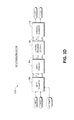
- FIG. 3E One example of a crosstalk canceller 350 is shown in more detail in FIG. 3E .
- This crosstalk canceller 350 b represents one of many possible implementations of the crosstalk canceller 350 a of FIG. 3D .
- the crosstalk canceller 350 b receives two signals, left and right, which have been processed with depth effects as described above. Each signal is inverted by an inverter 352 , 362 . The output of each inverter 352 , 362 is delayed by a delay block 354 , 364 . The output of the delay block is summed with an input signal at summer 356 , 366 . Thus, each signal is inverted, delayed, and summed with the opposite input signal to produce an output signal. If the delay is chosen correctly, the inverted and delayed signal should cancel out or at least partially reduce the crosstalk due to backwave mixing (or other crosstalk).
- the delay in the delay blocks 354 , 364 can represent the difference in sound wave travel time between two ears and can depend on the distance of the listener to the speakers.
- the delay can be set by a manufacturer for a device incorporating the depth processing system 110 , 310 to match an expected delay for most users of the device. A device where the user sits close to the device (such as a laptop) is likely to have a shorter delay than a device where the user sits far from the device (such as a television).
- delay settings can be customized based on the type of device used. These delay settings can be exposed in a user interface for selection by a user (e.g., the manufacturer of the device, installer of software on the device, or end-user, etc.). Alternatively, the delay can be preset.
- the delay can change dynamically based on position information obtained about a position of a listener relative to the speakers. This position information can be obtained from a camera or optical sensor, such as the XboxTM KinectTM available from MicrosoftTM Corporation.
- crosstalk cancellers may also include head-related transfer function (HRTF) filters or the like. If the surround processor 340 , which may already include HRTF-derived filters, were removed from the system, adding HRTF filters to the crosstalk canceller 350 may provide a larger sweet spot and sense of spaciousness. Both the surround processor 340 and the crosstalk canceller 350 can include HRTF filters in some embodiments.
- HRTF head-related transfer function
- FIG. 4 illustrates an embodiment of a depth rendering process 400 that can be implemented by any of the depth processing systems 110 , 310 described herein or by other systems not described herein.
- the depth rendering process 400 illustrates an example approach for rendering depth to create an immersive audio listening experience.
- input audio including one or more audio signals is received.
- the two or more audio signals can include left and right stereo signals, 5.1 surround signals as described above, other surround configurations (e.g., 6.1, 7.1, etc.), audio objects, or even monophonic audio that the depth processing system can convert to stereo prior to depth rendering.
- depth information associated with the input audio over a period of time is estimated. The depth information may be estimated directly from an analysis of the audio itself, as described above (see also FIG. 5 ), from video information, from object metadata, or from any combination of the same.
- the one or more audio signals are dynamically decorrelated by an amount that depends on the estimated depth information at block 406 .
- the decorrelated audio is output at block 408 .
- This decorrelation can involve adjusting phase and/or gain delays between two channels of audio dynamically based on the estimated depth.
- the estimated depth can therefore act as a steering signal that drives the amount of decorrelation created.
- the decorrelation can change dynamically in a corresponding fashion. For instance, in a stereo setting, if a sound moves from a left to right speaker, the left speaker output may first be emphasized, followed by the right speaker output being emphasized as the sound source moves to the right speaker.
- decorrelation can effectively result in increasing the difference between two channels, producing a greater L ⁇ R or LS ⁇ RS value.
- FIG. 5 illustrates a more detailed embodiment of a depth estimator 520 .
- the depth estimator 520 can implement any of the features of the depth estimators 320 described above.
- the depth estimator 520 estimates depth based on left and right input signals and provides outputs to a depth renderer 530 .
- the depth estimator 520 can also be used to estimate depth from left and right surround input signals. Further, embodiments of the depth estimator 520 can be used in conjunction with video depth estimators or object filter transform modules described herein.
- the left and right signals are provided to sum and difference blocks 502 , 504 .
- the depth estimator 520 receives a block of left and right samples at a time. The remainder of the depth estimator 520 can therefore manipulate the block of samples.
- the sum block 502 produces an L+R output
- the difference block 504 produces an L ⁇ R output.
- Each of these outputs, along with the original inputs, is provided to an envelope detector 510 .
- the envelope detector 510 can use any of a variety of techniques to detect envelopes in the L+R, L ⁇ R, L, and R signals (or a subset thereof).
- One envelope detection technique is to take a root-mean square (RMS) value of a signal.
- Envelope signals output by the envelope detector 510 are therefore shown as RMS(L ⁇ R), RMS(L), RMS(R), and RMS(L+R).
- RMS root-mean square
- These RMS outputs are provided to a smoother 512 , which applies a smoothing filter to the RMS outputs. Taking the envelope and smoothing the audio signals can smooth out variations (such as peaks) in the audio signals, thereby avoiding or reducing subsequent abrupt or jarring changes in depth processing.
- the smoother 512 is a fast-attack, slow-decay (FASD) smoother.
- the smoother 512 can be omitted.
- the outputs of the smoother 512 are denoted as RMS( )′ in FIG. 5 .
- the RMS(L ⁇ R)′ signal is provided to a depth calculator 524 .
- the magnitude of the L ⁇ R signal can reflect depth information in the two input signals.
- the magnitude of the RMS and smoothed L ⁇ R signal can also reflect depth information.
- larger magnitudes in the RMS(L ⁇ R)′ signal can reflect closer signals than smaller magnitudes of the RMS(L ⁇ R)′ signal.
- the values of the L ⁇ R or RMS(L ⁇ R)′ signal reflect the degree of correlation between the L ⁇ R signals.
- the L ⁇ R or RMS(L ⁇ R)′ (or RMS(L ⁇ R)) signal can be an inverse indicator of the interaural cross-correlation coefficient (IACC) between the left and right signals.
- IACC interaural cross-correlation coefficient
- the RMS(L ⁇ R)′ signal can reflect the inverse correlation between L and R signals, the RMS(L ⁇ R)′ signal can be used to determine how much decorrelation to apply between the L and R output signals.
- the depth calculator 524 can further process the RMS(L ⁇ R)′ signal to provide a depth estimate, which can be used to apply decorrelation to the L and R signals.
- the depth calculator 524 normalizes the RMS(L ⁇ R)′ signal.
- the RMS values can be divided by a geometric mean (or other mean or statistical measure) of the L and R signals (e.g., (RMS(L)′*RMS(R)′) ⁇ (1 ⁇ 2)) to normalize the envelope signals.
- Normalization can help ensure that fluctuations in signal level or volume are not misinterpreted as fluctuations in depth.
- the RMS(L)′ and RMS(R)′ values are multiplied together at multiplication block 538 and provided to the depth calculator 524 , which can complete the normalization process.
- the depth calculator 524 can also apply additional processing. For instance, the depth calculator 524 may apply non-linear processing to the RMS(L ⁇ R)′ signal. This non-linear processing can accentuate the magnitude of the RMS(L ⁇ R)′ signal to thereby nonlinearly emphasize the existing decorrelation in the RMS(L ⁇ R)′ signal. Thus, fast changes in the L ⁇ R signal can be emphasized even more than slow changes to the L ⁇ R signal.
- the non-linear processing is a power function or exponential in one embodiment, or greater than linear increase in another embodiment.
- the depth calculator 524 provides the normalized and nonlinear-processed signal as a depth estimate to a coefficient calculation block 534 and to a surround scale block 536 .
- the coefficient calculation block 534 calculates coefficients of a depth rendering filter based on the magnitude of the depth estimate.
- the depth rendering filter is described in greater detail below with respect to FIGS. 6A and 6B .
- the coefficients generated by the calculation block 534 can affect the amount of phase delay and/or gain adjustment applied to the left and right audio signals.
- the calculation block 534 can generate coefficients that produce greater phase delay for greater values of the depth estimate and vice versa.
- the relationship between phase delay generated by the calculation block 534 and the depth estimate is nonlinear, such as a power function or the like.
- This power function can have a power that is optionally a tunable parameter based on the closeness of a listener to the speakers, which may be determined by the type of device in which the depth estimator 520 is implemented. Televisions may have a greater expected listener distance than cell phones, for example, and thus the calculation block 534 can tune the power function differently for these or other types of devices.
- the power function applied by the calculation block 534 can magnify the effect of the depth estimate, resulting in coefficients of the depth rendering filter that result in an exaggerated phase and/or amplitude delay.
- the relationship between the phase delay and the depth estimate is linear instead of nonlinear (or a combination of both).
- the surround scale module 536 can output a signal that adjusts an amount of surround processing applied by the optional surround processor 340 .
- the amount of decorrelation or spaciousness in the L ⁇ R content, as calculated by the depth estimate, can therefore modulate the amount of surround processing applied.
- the surround scale module 536 can output a scale value that has greater values for greater values of the depth estimate and lower values for lower values of the depth estimate.
- the surround scale module 536 applies nonlinear processing, such as a power function or the like, to the depth estimate to produce the scale value.
- the scale value can be some function of a power of the depth estimate.
- the scale value and the depth estimate have a linear instead of nonlinear relationship (or a combination of both). More detail on the processing applied by the scale value is described below with respect to FIGS. 13 through 16 .
- the RMS(L)′ and RMS(R)′ signals are also provided to a delay and amplitude calculation block 540 .
- the calculation block 540 can calculate the amount of delay to be applied in the depth rendering filter ( FIGS. 6A and 6B ), for example, by updating a variable delay line pointer.
- the calculation block 540 determines which of the L and R signals (or their RMS( ) equivalent) is dominant or higher in level.
- the calculation block 540 can determine this dominance by taking a ratio of the two signals, as RMS(L)′/RMS(R)′, with values greater than 1 indicating left dominance and less than 1 indicating right dominance (or vice versa if the numerator and denominator are reversed).
- the calculation block 540 can perform a simple difference of the two signals to determine the signal with the greater magnitude.
- the calculation block 540 can adjust a left portion of the depth rendering filter ( FIG. 6A ) to decrease the phase delay applied to the left signal. If the right signal is dominant, the calculation block 540 can perform the same for the filter applied to the right signal ( FIG. 6B ). As the dominance in the signals changes, the calculation block 540 can change the delay line values for the depth rendering filter, causing a push-pull change in phase delays over time between the left and right channels. This push-pull change in phase delay can be at least partly responsible for selectively increasing decorrelation between the channels and increasing correlation between the channels (e.g., during times when dominance changes). The calculation block 540 can fade between left and right delay dominance in response to changes in left and right signal dominance to avoid outputting jarring changes or signal artifacts.
- the calculation block 540 can calculate an overall gain to be applied to left and right channels based on the ratio of the left and right signals (or processed, e.g., RMS, values thereof).
- the calculation block 540 can change these gains in a push-pull fashion, similar to the push-pull change of the phase delays. For example, if the left signal is dominant, then the calculation block 540 can amplify the left signal and attenuate the right signal. As the right signal becomes dominant, the calculation block 540 can amplify the right signal and attenuate the left signal, and so on.
- the calculation block 540 can also crossfade gains between channels to avoid jarring gain transitions or signal artifacts.
- the delay and amplitude calculator calculates parameters that cause the depth renderer 530 to decorrelate in phase delay and/or gain.
- the delay and amplitude calculator 540 can cause the depth renderer 530 to act as a magnifying glass or amplifier that amplifies existing phase and/or gain decorrelation between left and right signals. Either solely phase delay decorrelation or gain decorrelation may be performed in any given embodiment.
- the depth calculator 524 , coefficient calculation block 534 , and calculation block 540 can work together to control the depth renderer's 530 depth rendering effect.
- the amount of depth rendering brought about by decorrelation can depend on possibly multiple factors, such as the dominant channel and the (optionally processed) difference information (e.g., L ⁇ R and the like).
- the coefficient calculation from block 534 based on the difference information can turn on or off a phase delay effect provided by the depth renderer 530 .
- the difference information effectively controls whether phase delay is performed, while the channel dominance information controls the amount of phase delay and/or gain decorrelation is performed.
- the difference information also affects the amount of phase decorrelation and/or gain decorrelation performed.
- the output of the depth calculator 524 can be used to control solely an amount of phase and/or amplitude decorrelation, while the output of the calculation block 540 can be used to control coefficient calculation (e.g., can be provided to the calculation block 534 ).
- the output of the depth calculator 524 is provided to the calculation block 540 , and the phase and amplitude decorrelation parameter outputs of the calculation block 540 are controlled based on both the difference information and the dominance information.
- the coefficient calculation block 534 could take additional inputs from the calculation block 540 and compute the coefficients based on both difference information and dominance information.
- the RMS(L+R)′ signal is also provided to a non-linear processing (NLP) block 522 in the depicted embodiment.
- the NLP block 522 can perform similar NLP processing to the RMS(L+R)′ signal as was applied by the depth calculator 524 , for example, by applying an exponential function to the RMS(L+R)′ signal.
- the L+R information includes dialog and is often used as a replacement for a center channel. Emphasizing the value of the L+R block via nonlinear processing can be useful in determining how much dynamic range compression to apply to the L+R or C signal. Greater values of compression can result in louder and therefore clearer dialog.
- the output of the NLP block 522 can be used by a compression scale block 550 to adjust the amount of compression applied to the L+R or C signal.
- the depth estimator 520 can be modified or omitted in different implementations.
- the envelope detector 510 or smoother 512 may be omitted.
- depth estimations can be made based directly on the L ⁇ R signal, and signal dominance can be based directly on the L and R signals.
- the depth estimate and dominance calculations (as well as compression scale calculations based on L+R) can be smoothed instead of smoothing the input signals.
- the L ⁇ R signal (or a smoothed/envelope version thereof) or the depth estimate from the depth calculator 524 can be used to adjust the delay line pointer calculation in the calculation block 540 .
- the dominance between L and R signals can be used to manipulate the coefficient calculations in block 534 .
- the compression scale block 550 or surround scale block 536 may be omitted as well.
- Many other additional aspects may also be included in the depth estimator 520 , such as video depth estimation, which is described in greater detail below.
- FIGS. 6A and 6B illustrate embodiments of depth renderers 630 a , 630 b and represent more detailed embodiments of the depth renderers 330 , 530 described above.
- the depth renderer 630 a in FIG. 6A applies a depth rendering filter for the left channel
- the depth renderer 630 b in FIG. 6B applies a depth rendering filter for the right channel.
- the components shown in each FIGURE are therefore the same (although differences may be provided between the two filters in some embodiments).
- the depth renders 630 a , 630 b will be described generically as a single depth renderer 630 .
- the depth estimator 520 described above can provide several inputs to the depth renderer 630 . These inputs include one or more delay line pointers provided to variable delay lines 610 , 622 , feedforward coefficients applied to multiplier 602 , feedback coefficients applied to multiplier 616 , and an overall gain value applied to multiplier 624 (e.g., obtained from block 540 of FIG. 5 ).
- the depth renderer 630 is, in certain embodiments, an all-pass filter that can adjust the phase of the input signal.
- the depth renderer 630 is an infinite impulse response (IIR) filter having a feed-forward component 632 and a feedback component 634 .
- the feedback component 634 can be omitted to obtain a substantially similar phase-delay effect.
- a comb-filter effect can occur that potentially causes some audio frequencies to be nulled or otherwise attenuated.
- the feedback component 634 can advantageously reduce or eliminate this comb-filter effect.
- the feed-forward component 632 represents the zeros of the filter 630 A, while the feedback component represents the poles of the filter (see FIGS. 7 and 8 ).
- the feed-forward component 632 includes a variable delay line 610 , a multiplier 602 , and a combiner 612 .
- the variable delay line 610 takes as input the input signal (e.g., the left signal in FIG. 6A ), delays the signal according to an amount determined by the depth estimator 520 , and provides the delayed signal to the combiner 612 .
- the input signal is also provided to the multiplier 602 , which scales the signal and provides the scaled signal to the combiner 612 .
- the multiplier 602 represents the feed-forward coefficient calculated by the coefficient calculation block 534 of FIG. 5 .
- the output of the combiner 612 is provided to the feedback component 634 , which includes a variable delay line 622 , a multiplier 616 , and a combiner 614 .
- the output of the feed-forward component 632 is provided to the combiner 614 , which provides an output to the variable delay line 622 .
- the variable delay line 622 has a corresponding delay to the delay of the variable delay line 610 and depends on an output by the depth estimator 520 (see FIG. 5 ).
- the output of the delay line 622 is a delayed signal that is provided to the multiplier block 616 .
- the multiplier block 616 applies the feedback coefficient calculated by the coefficient calculation block 534 (see FIG. 5 ).
- the output of this block 616 is provided to the combiner 614 , which also provides an output to a multiplier 624 .
- This multiplier 624 applies an overall gain (described below) to the output of the depth rendering filter 630 .
- the multiplier 602 of the feed-forward component 632 can control a wet/dry mix of the input signal plus the delayed signal. More gain applied to the multiplier 602 can increase the amount of input signal (the dry or less reverberant signal) versus the delayed signal (the wet or more reverberant signal), and vice versa. Applying less gain to the input signal can cause the phase-delayed version of the input signal to predominate, emphasizing a depth effect, and vice versa. An inverted version of this gain (not shown) may be included in the variable delay block 610 to compensate for the extra gain applied by the multiplier 602 .
- the gain of the multiplier 616 can be chosen to correspond with the gain 602 so as to appropriately cancel out the comb-filter nulls. The gain of the multiplier 602 can therefore, in certain embodiments, modulate a time-varying wet-dry mix.
- the two depth rendering filters 630 A, 630 B can be controlled by the depth estimator 520 to selectively correlate and decorrelate the left and right input signals (or LS and RS signals).
- the left delay line 610 FIG. 6A
- the right delay line 610 FIG. 6B
- Adjusting the delays in an opposite manner between the two channels can create phase differences between the channels and thereby decorrelate the channels.
- an interaural intensity difference can be created by adjusting the left gain (multiplier block 624 in FIG.
- the depth estimator 520 can adjust the delays and gains in a push-pull fashion between the channels. Alternatively, only one of the left and right delays and/or gains are adjusted at any given time.
- the depth estimator 520 randomly varies the delays (in the delay lines 610 ) or gains 624 to randomly vary the ITD and IID differences in the two channels. This random variation can be small or large, but subtle random variations can result in a more natural-sounding immersive environment in some embodiments. Further, as sound sources move farther or closer away from the listener in the input audio signal, the depth rendering module can apply linear fading and/or smoothing (not shown) to the output of the depth rendering filter 630 to provide smooth transitions between depth adjustments in the two channels.
- the depth rendering filter 630 becomes a maximum phase filter with all zeros outside of the unit circle, and a phase delay is introduced.
- FIG. 7A shows a pole-zero plot 710 having zeros outside of the unit circle.
- FIG. 7B shows an example delay of about 32 samples corresponding to a relatively large value of the multiplier 602 coefficient.
- Other delay values can be set by adjusting the value of the multiplier 602 coefficient.
- the depth rendering filter 630 becomes a minimum phase filter, with its zeros inside the unit circle.
- the phase delay is zero (or close to zero).
- FIG. 8A shows a pole-zero plot 810 having all zeros inside the unit circle.
- FIG. 8B shows a delay of 0 samples.
- FIG. 9 illustrates an example frequency-domain depth estimation process 900 .
- the frequency-domain process 900 can be implemented by any of the systems 110 , 310 described above and may be used in place of the time-domain filters described above with respect to FIGS. 6A through 8B .
- depth rendering can be performed in either the time domain or the frequency domain (or both).
- various frequency domain techniques can be used to render the left and right signals so as to emphasize depth.
- the fast Fourier transform FFT
- the phase of each FFT signal can then be adjusted to create phase differences between the signals.
- intensity differences can be applied to the two FFT signals.
- An inverse-FFT can be applied to each signal to produce time-domain, rendered output signals.
- a stereo block of samples is received.
- the stereo block of samples can include left and right audio signals.
- a window function 904 is applied to the block of samples at block 904 . Any suitable window function can be selected, such as a Hamming window or Hanning window.
- the Fast Fourier Transform (FFT) is computed for each channel at block 906 to produce a frequency domain signal, and magnitude and phase information are extracted at block 908 from each channel's frequency domain signal.
- FFT Fast Fourier Transform
- Phase delays for ITD effects can be accomplished in the frequency domain by changing the phase angle of the frequency domain signal.
- magnitude changes for IID effects between the two channels can be accomplished by panning between the two channels.
- frequency dependent angles and panning are computed at blocks 910 and 912 .
- These angles and panning gain values can be computed based at least in part on control signals output by the depth estimator 320 or 520 .
- a dominant control signal from the depth estimator 520 indicating that the left channel is dominant can cause the frequency dependent panning to calculate gains over a series of samples that will pan to the left channel.
- the RMS(L ⁇ R)′ signal or the like can be used to compute phase changes as reflected in the changing phase angles.
- phase angles and panning changes are applied to the frequency domain signals at block 914 using a rotation transform, for example, using polar complex phase shifts.
- Magnitude and phase information are updated in each signal at block 916 .
- the magnitude and phase information are then unconverted from polar to Cartesian complex form at block 918 to enable inverse FFT processing. This unconversion step can be omitted in some embodiments, depending on the choice of FFT algorithm.
- An inverse FFT is computed for each frequency domain signal at block 920 to produce time domain signals.
- the stereo sample block is then combined with a preceding stereo sample block using overlap-add synthesis at block 922 and then output at block 924 .
- FIGS. 10A and 10B illustrate examples of video frames 1000 that can be used to estimate depth.
- a video frame 1000 A depicts a color scene from a video.
- a simplified scene has been selected to more conveniently illustrate depth mapping, although no audio is likely emitted from any of the objects in the particular video frame 1000 A shown.
- a grayscale depth map may be created using currently-available techniques, as shown in a grayscale frame 1000 B in FIG. 10B .
- the intensity of the pixels in the grayscale image reflect the depth of the pixels in the image, with darker pixels reflecting greater depth and lighter pixels reflecting less depth (these conventions can be reversed).
- a depth estimator e.g., 320
- a depth renderer e.g., 330
- the depth renderer can render a depth effect in an audio signal that corresponds to the time in the video that a particular frame is shown, for which depth information has been obtained (see FIG. 11 ).
- FIG. 11 illustrates an embodiment of a depth estimation and rendering algorithm 1100 that can be used to estimate depth from video data.
- the algorithm 1100 receives a grayscale depth map 1102 of a video frame and a spectral pan audio depth map 1104 .
- An instant in time in the audio depth map 1104 can be selected which corresponds to the time at which the video frame is played.
- a correlator 1110 can combine depth information obtained from the grayscale depth map 1102 with depth information obtained from the spectral pan audio map (or L ⁇ R, L, and/or R signals).
- the output of this correlator 1110 can be one or more depth steering signals that control depth rendering by a depth renderer 1130 (or 330 or 630 ).
- the depth estimator (not shown) can divide the grayscale depth map into regions, such as quadrants, halves, or the like. The depth estimator can then analyze pixel depths in the regions to determine which region is dominant. If a left region is dominant, for instance, the depth estimator can generate a steering signal that causes the depth renderer 1130 to emphasize left signals. The depth estimator can generate this steering signal in combination with the audio steering signal(s), as described above (see FIG. 5 ), or independently without using the audio signal.
- FIG. 12 illustrates an example analysis plot 1200 of depth based on video data.
- peaks reflect correlation between the video and audio maps of FIG. 11 .
- the depth estimator can decorrelate the audio signals correspondingly to emphasize the depth in the video and audio signals.
- depth-rendered left and right signals are provided to an optional surround processing module 340 a .
- the surround processor 340 a can broaden the sound stage, thereby widening the sweet spot and increasing the sense of depth, using one or more perspective curves or the like described in U.S. Pat. No. 7,492,907, incorporated above.
- one of the control signals can be used to modulate the surround processing applied by the surround processing module (see FIG. 5 ). Because a greater magnitude of the L ⁇ R signal can reflect greater depth, more surround processing can be applied when L ⁇ R is relatively greater and less surround processing can be applied when L ⁇ R is relatively smaller.
- the surround processing can be adjusted by adjusting a gain value applied to the perspective curve(s). Adjusting the amount of surround processing applied can reduce the potentially adverse effects of applying too much surround processing when little depth is present in the audio signals.
- FIGS. 13 through 16 illustrate embodiments of surround processors.
- FIGS. 15 and 16 illustrate embodiments of perspective curves that can be used by the surround processors to create a virtual surround effect.
- the surround processor 1340 is a more detailed embodiment of the surround processor 340 described above.
- the surround processor 1340 includes a decoder 1380 , which may be a passive matrix decoder, Circle Surround decoder (see U.S. Pat. No. 5,771,295, titled “5-2-5 Matrix System,” the disclosure of which is hereby incorporated by reference in its entirety), or the like.
- the decoder 1380 can decode left and right input signals (received, e.g., from the depth renderer 330 a ) into multiple signals that can be surround-processed with perspective curve filter(s) 1390 .
- the output of the decoder 1380 includes left, right, center, and surround signals.
- the surround signals may include both left and right surround or simply a single surround signal.
- the decoder 1380 synthesizes a center signal by summing L and R signals (L+R) and synthesizes a rear surround signal by subtracting R from L (L ⁇ R).
- One or more perspective curve filter(s) 1390 can provide a spaciousness enhancement to the signals output by the decoder 1380 , which can widen the sweet spot for the purposes of depth rendering, as described above.
- the spaciousness or perspective effect provided by these filter(s) 1390 can be modulated or adjusted based on L ⁇ R difference information, as shown.
- This L ⁇ R difference information may be processed L ⁇ R difference information according to the envelope, smoothing, and/or normalization effects described above with respect to FIG. 5 .
- the surround effect provided by the surround processor 1340 can be used independently of depth rendering. Modulation of this surround effect by the difference information in the left and right signals can enhance the quality of the sound effect independent of depth rendering.
- FIG. 14 illustrates a more detailed embodiment of a surround processor 1400 .
- the surround processor 1400 can be used to implement any of the features of the surround processors described above, such as the surround processor 1340 .
- no decoder is shown. Instead, audio inputs ML (left front), MR (right front), Center (CIN), optional subwoofer (B), left surround (SL), and right surround (SR) are provided to the surround processor 1400 , which applies perspective curve filters 1470 , 1406 , and 1420 to various mixings of the audio inputs.
- the signals ML and MR are fed to corresponding gain-adjusting multipliers 1452 and 1454 which are controlled by a volume adjustment signal Mvolume.
- the gain of the center signal C may be adjusted by a first multiplier 1456 , controlled by the signal Mvolume, and a second multiplier 1458 controlled by a center adjustment signal Cvolume.
- the surround signals SL and SR are first fed to respective multipliers 1460 and 1462 which are controlled by a volume adjustment signal Svolume.
- the main front left and right signals, ML and MR are each fed to summing junctions 1464 and 1466 .
- the summing junction 1464 has an inverting input which receives MR and a non-inverting input which receives ML which combine to produce ML ⁇ MR along an output path 1468 .
- the signal ML ⁇ MR is fed to a perspective curve filter 1470 which is characterized by a transfer function P 1 .
- a processed difference signal, (ML ⁇ MR)p is delivered at an output of the perspective curve filter 1470 to a gain adjusting multiplier 1472 .
- the gain adjusting multiplier 1472 can apply the surround scale 536 setting described above with respect to FIG. 5 .
- the output of the perspective curve filter 1470 can be modulated based on the difference information in the L ⁇ R signal.
- the output of the multiplier 1472 is fed directly to a left mixer 1480 and to an inverter 1482 .
- the inverted difference signal (MR ⁇ ML)p is transmitted from the inverter 1482 to a right mixer 1484 .
- a summation signal ML+MR exits the junction 1466 and is fed to a gain adjusting multiplier 1486 .
- the gain adjusting multiplier 1486 may also apply the surround scale 536 setting described above with respect to FIG. 5 or some other gain setting.
- the output of the multiplier 1486 is fed to a summing junction which adds the center channel signal, C, with the signal ML+MR.
- the combined signal, ML+MR+C exits the junction 1490 and is directed to both the left mixer 1480 and the right mixer 1484 .
- the original signals ML and MR are first fed through fixed gain adjustment components, e.g., amplifiers, 1490 and 1492 , respectively, before transmission to the mixers 1480 and 1484 .
- the summing junction 1401 has an inverting input which receives SR and a non-inverting input which receives SL which combine to produce SL ⁇ SR along an output path 1404 .
- All of the summing junctions 1464 , 1466 , 1400 , and 1402 may be configured as either an inverting amplifier or a non-inverting amplifier, depending on whether a sum or difference signal is generated. Both inverting and non-inverting amplifiers may be constructed from ordinary operational amplifiers in accordance with principles common to one of ordinary skill in the art.
- the signal SL ⁇ SR is fed to a perspective curve filter 1406 which is characterized by a transfer function P 2 .
- a processed difference signal, (SL ⁇ SR)p is delivered at an output of the perspective curve filter 1406 to a gain adjusting multiplier 1408 .
- the gain adjusting multiplier 1408 can apply the surround scale 536 setting described above with respect to FIG. 5 .
- This surround scale 536 setting may be the same or different than that applied by the multiplier 1472 .
- the multiplier 1408 is omitted or is dependent on a setting other than the surround scale 536 setting.
- the output of the multiplier 1408 is fed directly to the left mixer 1480 and to an inverter 1410 .
- the inverted difference signal (SR ⁇ SL)p is transmitted from the inverter 1410 to the right mixer 1484 .
- a summation signal SL+SR exits the junction 1402 and is fed to a separate perspective curve filter 1420 which is characterized by a transfer function P 3 .
- a processed summation signal, (SL+SR)p, is delivered at an output of the perspective curve filter 1420 to a gain adjusting multiplier 1432 .
- the gain adjusting multiplier 1432 can apply the surround scale 536 setting described above with respect to FIG. 5 . This surround scale 536 setting may be the same or different than that applied by the multipliers 1472 , 1408 . In another embodiment, the multiplier 1432 is omitted or is dependent on a setting other than the surround scale 536 setting.
- the output of the multiplier 1432 is fed directly to the left mixer 1480 and to the right mixer 1484 .
- the original signals SL and SR are first fed through fixed-gain amplifiers 1430 and 1434 , respectively, before transmission to the mixers 1480 and 1484 .
- the low-frequency effects channel, B is fed through an amplifier 1436 to create the output low-frequency effects signal, BOUT.
- the low frequency channel, B may be mixed as part of the output signals, LOUT and ROUT, if no subwoofer is available.
- the perspective curve filter 1470 may employ a variety of audio enhancement techniques.
- the perspective curve filters 1470 , 1406 , and 1420 may use time-delay techniques, phase-shift techniques, signal equalization, or a combination of all of these techniques to achieve a desired audio effect.
- the surround processor 1400 uniquely conditions a set of multi-channel signals to provide a surround sound experience through playback of the two output signals LOUT and ROUT.
- the signals ML and MR are processed collectively by isolating the ambient information present in these signals.
- the ambient signal component represents the differences between a pair of audio signals.
- An ambient signal component derived from a pair of audio signals is therefore often referred to as the “difference” signal component.
- the perspective curve filters 1470 , 1406 , and 1420 are shown and described as generating sum and difference signals, other embodiments of perspective curve filters 1470 , 1406 , and 1420 may not distinctly generate sum and difference signals at all.
- FIG. 15 illustrates example perspective curves 1500 that can be implemented by any of the surround processors described herein. These perspective curves 1500 are front perspective curves in one embodiment, which can be implemented by the perspective curve filter 1470 of FIG. 14 .
- FIG. 15 depicts an input 1502 , a ⁇ 15 dBFSs log sweep and also depicts traces 1504 , 1506 , and 1508 that show example magnitude responses of a perspective curve filter over the displayed frequency range.
- While the response shown by the traces in FIG. 15 are shown throughout the entire 20 Hz to 20 kHz frequency range, these response in certain embodiments need not be provided through the entire audible range.
- certain of the frequency responses can be truncated to, for instance, a 40 Hz to 10 kHz range with little or no loss of functionality. Other ranges may also be provided for the frequency responses.
- the traces 1504 , 1506 and 1508 illustrate example frequency responses of one or more of the perspective filters described above, such as the front or (optionally) rear perspective filters.
- These traces 1504 , 1506 , 1508 represent different levels of the perspective curve filters based on the surround scale 536 setting of FIG. 5 .
- a greater magnitude of the surround scale 536 setting can result in a greater magnitude curve (e.g., curve 1404 ), while lower magnitudes of the surround scale 536 setting can result in lower magnitude curves (e.g., 1406 or 1408 ).
- the actual magnitudes shown are merely examples only and can be varied. Further, more than three different magnitudes can be selected based on the surround scale value 536 in certain embodiments.
- the trace 1504 starts at about ⁇ 16 dBFS at about 20 Hz, and increases to about ⁇ 11 dBFS at about 100 Hz. Thereafter, the trace 1504 decreases to about ⁇ 17.5 dBFS at about 2 kHz and thereafter increases to about ⁇ 12.5 dBFS at about 15 kHz.
- the trace 1506 starts at about ⁇ 14 dBFS at about 20 Hz, and it increases to about ⁇ 10 dBFS at about 100 Hz, and decreases to about ⁇ 16 dBFS at about 2 kHz, and increases to about ⁇ 11 dBFS at about 15 kHz.
- the trace 1508 starts at about ⁇ 12.5 dBFS at about 20 Hz, and increases to about ⁇ 9 dBFS at about 100 Hz, and decreases to about ⁇ 14.5 dBFS at about 2 kHz, and increases to about ⁇ 10.2 dBFS at about 15 kHz.
- frequencies in about the 2 kHz range are de-emphasized by the perspective filter, and frequencies at about 100 Hz and about 15 kHz are emphasized by the perspective filters. These frequencies may be varied in certain embodiments.
- FIG. 16 illustrates another example of perspective curves 1600 that can be implemented by any of the surround processors described herein.
- These perspective curves 1600 are rear perspective curves in one embodiment, which can be implemented by the perspective curve filters 1406 or 1420 of FIG. 14 .
- an input log frequency sweep 1610 is shown, resulting in the output traces 1620 , 1630 of two different perspective curve filters.
- the perspective curve 1620 corresponds to a perspective curve filter applied to a surround difference signal.
- the perspective curve 1620 can be implemented by the perspective curve filter 1406 .
- the perspective curve 1620 corresponds in certain embodiments to a perspective curve filter applied to a surround sum signal.
- the perspective curve 1630 can be implemented by the perspective curve filter 1420 . Effective magnitudes of the curves 1620 , 1630 can vary based on the surround scale 536 setting described above.
- the curve 1620 has an approximately flat gain at about ⁇ 10 dBFS, which attenuates to a trough occurring between about 2 kHz and about 4 kHz, or at approximately between 2.5 kHz and 3 kHz. From this trough, the curve 1620 increases in magnitude until about 11 kHz, or between about 10 kHz and 12 kHz, where a peak occurs. After this peak, the curve 1620 attenuates again until about 20 kHz or less.
- the curve 1630 has a similar structure but with less pronounced peaks and troughs, with a flat curve until a trough at about 3 kHz (or between about 2 kHz and 4 khz), and a peak about 11 kHz (or between about 10 kHz and 12 kHz), with attenuation to about 20 kHz or less.
- curves shown are merely examples and can be varied in different embodiments.
- a high pass filter can be combined with the curves to change the flat low-frequency response to an attenuating low-frequency response.
- a machine such as a general purpose processor, a digital signal processor (DSP), an application specific integrated circuit (ASIC), a field programmable gate array (FPGA) or other programmable logic device, discrete gate or transistor logic, discrete hardware components, or any combination thereof designed to perform the functions described herein.
- DSP digital signal processor
- ASIC application specific integrated circuit
- FPGA field programmable gate array
- a general purpose processor can be a microprocessor, but in the alternative, the processor can be a controller, microcontroller, or state machine, combinations of the same, or the like.
- a processor can also be implemented as a combination of computing devices, e.g., a combination of a DSP and a microprocessor, a plurality of microprocessors, one or more microprocessors in conjunction with a DSP core, or any other such configuration. Although described herein primarily with respect to digital technology, a processor may also include primarily analog components. For example, any of the signal processing algorithms described herein may be implemented in analog circuitry.
- a computing environment can include any type of computer system, including, but not limited to, a computer system based on a microprocessor, a mainframe computer, a digital signal processor, a portable computing device, a personal organizer, a device controller, and a computational engine within an appliance, to name a few.
- a software module can reside in RAM memory, flash memory, ROM memory, EPROM memory, EEPROM memory, registers, hard disk, a removable disk, a CD-ROM, or any other form of non-transitory computer-readable storage medium, media, or physical computer storage known in the art.
- An exemplary storage medium can be coupled to the processor such that the processor can read information from, and write information to, the storage medium.
- the storage medium can be integral to the processor.
- the processor and the storage medium can reside in an ASIC.
- the ASIC can reside in a user terminal.
- the processor and the storage medium can reside as discrete components in a user terminal.
Priority Applications (1)
| Application Number | Priority Date | Filing Date | Title |
|---|---|---|---|
| US13/342,758 US9154897B2 (en) | 2011-01-04 | 2012-01-03 | Immersive audio rendering system |
Applications Claiming Priority (2)
| Application Number | Priority Date | Filing Date | Title |
|---|---|---|---|
| US201161429600P | 2011-01-04 | 2011-01-04 | |
| US13/342,758 US9154897B2 (en) | 2011-01-04 | 2012-01-03 | Immersive audio rendering system |
Publications (2)
| Publication Number | Publication Date |
|---|---|
| US20120170757A1 US20120170757A1 (en) | 2012-07-05 |
| US9154897B2 true US9154897B2 (en) | 2015-10-06 |
Family
ID=46380804
Family Applications (3)
| Application Number | Title | Priority Date | Filing Date |
|---|---|---|---|
| US13/342,743 Active US9088858B2 (en) | 2011-01-04 | 2012-01-03 | Immersive audio rendering system |
| US13/342,758 Active 2033-11-09 US9154897B2 (en) | 2011-01-04 | 2012-01-03 | Immersive audio rendering system |
| US14/801,652 Active US10034113B2 (en) | 2011-01-04 | 2015-07-16 | Immersive audio rendering system |
Family Applications Before (1)
| Application Number | Title | Priority Date | Filing Date |
|---|---|---|---|
| US13/342,743 Active US9088858B2 (en) | 2011-01-04 | 2012-01-03 | Immersive audio rendering system |
Family Applications After (1)
| Application Number | Title | Priority Date | Filing Date |
|---|---|---|---|
| US14/801,652 Active US10034113B2 (en) | 2011-01-04 | 2015-07-16 | Immersive audio rendering system |
Country Status (6)
| Country | Link |
|---|---|
| US (3) | US9088858B2 (fr) |
| EP (1) | EP2661907B8 (fr) |
| JP (1) | JP5955862B2 (fr) |
| KR (1) | KR101827036B1 (fr) |
| CN (1) | CN103329571B (fr) |
| WO (2) | WO2012094335A1 (fr) |
Cited By (3)
| Publication number | Priority date | Publication date | Assignee | Title |
|---|---|---|---|---|
| US20160044431A1 (en) * | 2011-01-04 | 2016-02-11 | Dts Llc | Immersive audio rendering system |
| US10187737B2 (en) | 2015-01-16 | 2019-01-22 | Samsung Electronics Co., Ltd. | Method for processing sound on basis of image information, and corresponding device |
| US10602296B2 (en) | 2017-06-09 | 2020-03-24 | Nokia Technologies Oy | Audio object adjustment for phase compensation in 6 degrees of freedom audio |
Families Citing this family (47)
| Publication number | Priority date | Publication date | Assignee | Title |
|---|---|---|---|---|
| EP2611178A3 (fr) * | 2011-12-29 | 2015-08-19 | Samsung Electronics Co., Ltd. | Appareil d'affichage et procédé pour le commander |
| TWI479905B (zh) * | 2012-01-12 | 2015-04-01 | Univ Nat Central | Multi-channel down mixing device |
| EP2811763A4 (fr) * | 2012-02-03 | 2015-06-17 | Panasonic Ip Man Co Ltd | Générateur de composante d'ambiance |
| US9264840B2 (en) * | 2012-05-24 | 2016-02-16 | International Business Machines Corporation | Multi-dimensional audio transformations and crossfading |
| US9332373B2 (en) * | 2012-05-31 | 2016-05-03 | Dts, Inc. | Audio depth dynamic range enhancement |
| CN103686136A (zh) * | 2012-09-18 | 2014-03-26 | 宏碁股份有限公司 | 多媒体处理系统及音频信号处理方法 |
| BR112015013154B1 (pt) | 2012-12-04 | 2022-04-26 | Samsung Electronics Co., Ltd | Aparelho fornecedor de áudio, e método fornecedor de áudio |
| PL2939443T3 (pl) | 2012-12-27 | 2018-07-31 | Dts, Inc. | Układ i sposób zmiennej dekorelacji sygnałów audio |
| US9258664B2 (en) | 2013-05-23 | 2016-02-09 | Comhear, Inc. | Headphone audio enhancement system |
| KR101984356B1 (ko) * | 2013-05-31 | 2019-12-02 | 노키아 테크놀로지스 오와이 | 오디오 장면 장치 |
| EP3020042B1 (fr) | 2013-07-08 | 2018-03-21 | Dolby Laboratories Licensing Corporation | Traitement de métadonnées à variation temporelle pour un ré-échantillonnage sans perte |
| KR20230007563A (ko) * | 2013-07-31 | 2023-01-12 | 돌비 레버러토리즈 라이쎈싱 코오포레이션 | 공간적으로 분산된 또는 큰 오디오 오브젝트들의 프로세싱 |
| CN108712711B (zh) | 2013-10-31 | 2021-06-15 | 杜比实验室特许公司 | 使用元数据处理的耳机的双耳呈现 |
| WO2015147533A2 (fr) * | 2014-03-24 | 2015-10-01 | 삼성전자 주식회사 | Procédé et appareil de rendu de signal sonore et support d'enregistrement lisible par ordinateur |
| US9837061B2 (en) * | 2014-06-23 | 2017-12-05 | Nxp B.V. | System and method for blending multi-channel signals |
| US9384745B2 (en) * | 2014-08-12 | 2016-07-05 | Nxp B.V. | Article of manufacture, system and computer-readable storage medium for processing audio signals |
| KR102482162B1 (ko) | 2014-10-01 | 2022-12-29 | 돌비 인터네셔널 에이비 | 오디오 인코더 및 디코더 |
| EP3213323B1 (fr) | 2014-10-31 | 2018-12-12 | Dolby International AB | Codage et décodage paramétriques de signaux audio à plusieurs canaux |
| CN106999788A (zh) | 2014-11-30 | 2017-08-01 | 杜比实验室特许公司 | 社交媒体链接的大幅面剧院设计 |
| US9551161B2 (en) | 2014-11-30 | 2017-01-24 | Dolby Laboratories Licensing Corporation | Theater entrance |
| US9691408B2 (en) * | 2014-12-16 | 2017-06-27 | Psyx Research, Inc. | System and method for dynamic equalization of audio data |
| CN106303897A (zh) | 2015-06-01 | 2017-01-04 | 杜比实验室特许公司 | 处理基于对象的音频信号 |
| CN105101039B (zh) * | 2015-08-31 | 2018-12-18 | 广州酷狗计算机科技有限公司 | 立体声还原方法及装置 |
| US10045145B2 (en) * | 2015-12-18 | 2018-08-07 | Qualcomm Incorporated | Temporal offset estimation |
| US10225657B2 (en) | 2016-01-18 | 2019-03-05 | Boomcloud 360, Inc. | Subband spatial and crosstalk cancellation for audio reproduction |
| CN108886650B (zh) * | 2016-01-18 | 2020-11-03 | 云加速360公司 | 用于音频再现的子带空间和串扰消除 |
| EP3453190A4 (fr) | 2016-05-06 | 2020-01-15 | DTS, Inc. | Systèmes de reproduction audio immersifs |
| US10057681B2 (en) | 2016-08-01 | 2018-08-21 | Bose Corporation | Entertainment audio processing |
| JP7014176B2 (ja) | 2016-11-25 | 2022-02-01 | ソニーグループ株式会社 | 再生装置、再生方法、およびプログラム |
| WO2018151858A1 (fr) * | 2017-02-17 | 2018-08-23 | Ambidio, Inc. | Appareil et procédé de sous-mixage de signaux audio multicanaux |
| US10979844B2 (en) | 2017-03-08 | 2021-04-13 | Dts, Inc. | Distributed audio virtualization systems |
| GB2561595A (en) * | 2017-04-20 | 2018-10-24 | Nokia Technologies Oy | Ambience generation for spatial audio mixing featuring use of original and extended signal |
| US10841726B2 (en) | 2017-04-28 | 2020-11-17 | Hewlett-Packard Development Company, L.P. | Immersive audio rendering |
| WO2019079602A1 (fr) * | 2017-10-18 | 2019-04-25 | Dts, Inc. | Préconditionnement de signal audio pour virtualisation audio 3d |
| US10524078B2 (en) * | 2017-11-29 | 2019-12-31 | Boomcloud 360, Inc. | Crosstalk cancellation b-chain |
| US10609504B2 (en) * | 2017-12-21 | 2020-03-31 | Gaudi Audio Lab, Inc. | Audio signal processing method and apparatus for binaural rendering using phase response characteristics |
| KR20190083863A (ko) * | 2018-01-05 | 2019-07-15 | 가우디오랩 주식회사 | 오디오 신호 처리 방법 및 장치 |
| US10764704B2 (en) * | 2018-03-22 | 2020-09-01 | Boomcloud 360, Inc. | Multi-channel subband spatial processing for loudspeakers |
| WO2019191611A1 (fr) | 2018-03-29 | 2019-10-03 | Dts, Inc. | Commande de plage dynamique de protection de centre |
| KR102531634B1 (ko) * | 2018-08-10 | 2023-05-11 | 삼성전자주식회사 | 오디오 장치 및 그 제어방법 |
| CN109348390B (zh) * | 2018-09-14 | 2021-07-16 | 张小夫 | 一种沉浸式全景声电子音乐扩散系统的实现方法 |
| CN113170253B (zh) * | 2018-10-05 | 2024-03-19 | 奇跃公司 | 用于音频空间化的加重 |
| CN111757239B (zh) * | 2019-03-28 | 2021-11-19 | 瑞昱半导体股份有限公司 | 音频处理方法与音频处理系统 |
| US11026037B2 (en) * | 2019-07-18 | 2021-06-01 | International Business Machines Corporation | Spatial-based audio object generation using image information |
| US11270712B2 (en) | 2019-08-28 | 2022-03-08 | Insoundz Ltd. | System and method for separation of audio sources that interfere with each other using a microphone array |
| US10841728B1 (en) | 2019-10-10 | 2020-11-17 | Boomcloud 360, Inc. | Multi-channel crosstalk processing |
| US11533560B2 (en) | 2019-11-15 | 2022-12-20 | Boomcloud 360 Inc. | Dynamic rendering device metadata-informed audio enhancement system |
Citations (159)
| Publication number | Priority date | Publication date | Assignee | Title |
|---|---|---|---|---|
| US3170991A (en) | 1963-11-27 | 1965-02-23 | Glasgal Ralph | System for stereo separation ratio control, elimination of cross-talk and the like |
| FI35014A (fi) | 1962-12-13 | 1965-05-10 | Äänentoistojärjestelmä | |
| US3229038A (en) | 1961-10-31 | 1966-01-11 | Rca Corp | Sound signal transforming system |
| US3246081A (en) | 1962-03-21 | 1966-04-12 | William C Edwards | Extended stereophonic systems |
| US3249696A (en) | 1961-10-16 | 1966-05-03 | Zenith Radio Corp | Simplified extended stereo |
| JPS4312585Y1 (fr) | 1965-12-17 | 1968-05-30 | ||
| US3665105A (en) | 1970-03-09 | 1972-05-23 | Univ Leland Stanford Junior | Method and apparatus for simulating location and movement of sound |
| US3697692A (en) | 1971-06-10 | 1972-10-10 | Dynaco Inc | Two-channel,four-component stereophonic system |
| US3725586A (en) | 1971-04-13 | 1973-04-03 | Sony Corp | Multisound reproducing apparatus for deriving four sound signals from two sound sources |
| US3745254A (en) | 1970-09-15 | 1973-07-10 | Victor Company Of Japan | Synthesized four channel stereo from a two channel source |
| US3757047A (en) | 1970-05-21 | 1973-09-04 | Sansui Electric Co | Four channel sound reproduction system |
| US3761631A (en) | 1971-05-17 | 1973-09-25 | Sansui Electric Co | Synthesized four channel sound using phase modulation techniques |
| US3772479A (en) | 1971-10-19 | 1973-11-13 | Motorola Inc | Gain modified multi-channel audio system |
| US3849600A (en) | 1972-10-13 | 1974-11-19 | Sony Corp | Stereophonic signal reproducing apparatus |
| US3885101A (en) | 1971-12-21 | 1975-05-20 | Sansui Electric Co | Signal converting systems for use in stereo reproducing systems |
| US3892624A (en) | 1970-02-03 | 1975-07-01 | Sony Corp | Stereophonic sound reproducing system |
| US3925615A (en) | 1972-02-25 | 1975-12-09 | Hitachi Ltd | Multi-channel sound signal generating and reproducing circuits |
| US3943293A (en) | 1972-11-08 | 1976-03-09 | Ferrograph Company Limited | Stereo sound reproducing apparatus with noise reduction |
| US4024344A (en) | 1974-11-16 | 1977-05-17 | Dolby Laboratories, Inc. | Center channel derivation for stereophonic cinema sound |
| US4063034A (en) | 1976-05-10 | 1977-12-13 | Industrial Research Products, Inc. | Audio system with enhanced spatial effect |
| US4069394A (en) | 1975-06-05 | 1978-01-17 | Sony Corporation | Stereophonic sound reproduction system |
| US4118599A (en) | 1976-02-27 | 1978-10-03 | Victor Company Of Japan, Limited | Stereophonic sound reproduction system |
| US4139728A (en) | 1976-04-13 | 1979-02-13 | Victor Company Of Japan, Ltd. | Signal processing circuit |
| US4192969A (en) | 1977-09-10 | 1980-03-11 | Makoto Iwahara | Stage-expanded stereophonic sound reproduction |
| US4204092A (en) | 1978-04-11 | 1980-05-20 | Bruney Paul F | Audio image recovery system |
| US4209665A (en) | 1977-08-29 | 1980-06-24 | Victor Company Of Japan, Limited | Audio signal translation for loudspeaker and headphone sound reproduction |
| US4218583A (en) | 1978-07-28 | 1980-08-19 | Bose Corporation | Varying loudspeaker spatial characteristics |
| US4218585A (en) | 1979-04-05 | 1980-08-19 | Carver R W | Dimensional sound producing apparatus and method |
| US4219696A (en) | 1977-02-18 | 1980-08-26 | Matsushita Electric Industrial Co., Ltd. | Sound image localization control system |
| JPS55152571U (fr) | 1979-04-19 | 1980-11-04 | ||
| US4237343A (en) | 1978-02-09 | 1980-12-02 | Kurtin Stephen L | Digital delay/ambience processor |
| US4239937A (en) | 1979-01-02 | 1980-12-16 | Kampmann Frank S | Stereo separation control |
| US4303800A (en) | 1979-05-24 | 1981-12-01 | Analog And Digital Systems, Inc. | Reproducing multichannel sound |
| US4308424A (en) | 1980-04-14 | 1981-12-29 | Bice Jr Robert G | Simulated stereo from a monaural source sound reproduction system |
| US4308423A (en) | 1980-03-12 | 1981-12-29 | Cohen Joel M | Stereo image separation and perimeter enhancement |
| US4309570A (en) | 1979-04-05 | 1982-01-05 | Carver R W | Dimensional sound recording and apparatus and method for producing the same |
| US4332979A (en) | 1978-12-19 | 1982-06-01 | Fischer Mark L | Electronic environmental acoustic simulator |
| US4349698A (en) | 1979-06-19 | 1982-09-14 | Victor Company Of Japan, Limited | Audio signal translation with no delay elements |
| US4355203A (en) | 1980-03-12 | 1982-10-19 | Cohen Joel M | Stereo image separation and perimeter enhancement |
| US4356349A (en) | 1980-03-12 | 1982-10-26 | Trod Nossel Recording Studios, Inc. | Acoustic image enhancing method and apparatus |
| US4393270A (en) | 1977-11-28 | 1983-07-12 | Berg Johannes C M Van Den | Controlling perceived sound source direction |
| US4394536A (en) | 1980-06-12 | 1983-07-19 | Mitsubishi Denki Kabushiki Kaisha | Sound reproduction device |
| JPS58144989U (ja) | 1982-03-19 | 1983-09-29 | クラリオン株式会社 | 音響機器 |
| US4408095A (en) | 1980-03-04 | 1983-10-04 | Clarion Co., Ltd. | Acoustic apparatus |
| JPS5927692Y2 (ja) | 1976-11-08 | 1984-08-10 | カヤバ工業株式会社 | 農用トラクタの作業機及びアタツチメント用コントロ−ル弁 |
| US4479235A (en) | 1981-05-08 | 1984-10-23 | Rca Corporation | Switching arrangement for a stereophonic sound synthesizer |
| US4489432A (en) | 1982-05-28 | 1984-12-18 | Polk Audio, Inc. | Method and apparatus for reproducing sound having a realistic ambient field and acoustic image |
| US4495637A (en) | 1982-07-23 | 1985-01-22 | Sci-Coustics, Inc. | Apparatus and method for enhanced psychoacoustic imagery using asymmetric cross-channel feed |
| US4497064A (en) | 1982-08-05 | 1985-01-29 | Polk Audio, Inc. | Method and apparatus for reproducing sound having an expanded acoustic image |
| US4503554A (en) | 1983-06-03 | 1985-03-05 | Dbx, Inc. | Stereophonic balance control system |
| DE3331352A1 (de) | 1983-08-31 | 1985-03-14 | Blaupunkt-Werke Gmbh, 3200 Hildesheim | Schaltungsanordnung und verfahren fuer wahlweisen mono- und stereo-ton-betrieb von ton- und bildrundfunkemfaengern und -recordern |
| GB2154835A (en) | 1984-02-21 | 1985-09-11 | Kintek Inc | Signal decoding system |
| EP0097982A3 (fr) | 1982-06-03 | 1985-12-27 | CARVER, Robert Weir | Appareil FM stéreo |
| US4567607A (en) | 1983-05-03 | 1986-01-28 | Stereo Concepts, Inc. | Stereo image recovery |
| US4569074A (en) | 1984-06-01 | 1986-02-04 | Polk Audio, Inc. | Method and apparatus for reproducing sound having a realistic ambient field and acoustic image |
| US4594730A (en) | 1984-04-18 | 1986-06-10 | Rosen Terry K | Apparatus and method for enhancing the perceived sound image of a sound signal by source localization |
| US4594610A (en) | 1984-10-15 | 1986-06-10 | Rca Corporation | Camera zoom compensator for television stereo audio |
| US4594729A (en) | 1982-04-20 | 1986-06-10 | Neutrik Aktiengesellschaft | Method of and apparatus for the stereophonic reproduction of sound in a motor vehicle |
| JPS6133600Y2 (fr) | 1980-06-17 | 1986-10-01 | ||
| JPS61166696U (fr) | 1985-04-04 | 1986-10-16 | ||
| US4622691A (en) | 1984-05-31 | 1986-11-11 | Pioneer Electronic Corporation | Mobile sound field correcting device |
| US4648117A (en) | 1984-05-31 | 1987-03-03 | Pioneer Electronic Corporation | Mobile sound field correcting device |
| US4696036A (en) | 1985-09-12 | 1987-09-22 | Shure Brothers, Inc. | Directional enhancement circuit |
| WO1987006090A1 (fr) | 1986-03-27 | 1987-10-08 | Hughes Aircraft Company | Systeme d'amelioration d'images sonores stereo |
| US4703502A (en) | 1985-01-28 | 1987-10-27 | Nissan Motor Company, Limited | Stereo signal reproducing system |
| EP0312406A2 (fr) | 1987-10-15 | 1989-04-19 | Personics Corporation | Programme audio avec possibilité de reproduction à grande vitesse |
| EP0320270A2 (fr) | 1987-12-09 | 1989-06-14 | Canon Kabushiki Kaisha | Système de production de son stéréophonique avec directivité contrôlée |
| US4856064A (en) | 1987-10-29 | 1989-08-08 | Yamaha Corporation | Sound field control apparatus |
| US4862502A (en) | 1988-01-06 | 1989-08-29 | Lexicon, Inc. | Sound reproduction |
| US4866776A (en) | 1983-11-16 | 1989-09-12 | Nissan Motor Company Limited | Audio speaker system for automotive vehicle |
| US4866774A (en) | 1988-11-02 | 1989-09-12 | Hughes Aircraft Company | Stero enhancement and directivity servo |
| US4888809A (en) | 1987-09-16 | 1989-12-19 | U.S. Philips Corporation | Method of and arrangement for adjusting the transfer characteristic to two listening position in a space |
| EP0354517A2 (fr) | 1988-08-12 | 1990-02-14 | Sanyo Electric Co., Ltd. | Circuit de commande pour canal central |
| EP0357402A2 (fr) | 1988-09-02 | 1990-03-07 | Q Sound Ltd | Méthode et appareil de génération d'image sonore |
| EP0367569A2 (fr) | 1988-10-31 | 1990-05-09 | Kabushiki Kaisha Toshiba | Système à effet sonore |
| US4933768A (en) | 1988-07-20 | 1990-06-12 | Sanyo Electric Co., Ltd. | Sound reproducer |
| US4953213A (en) | 1989-01-24 | 1990-08-28 | Pioneer Electronic Corporation | Surround mode stereophonic reproducing equipment |
| US5033092A (en) | 1988-12-07 | 1991-07-16 | Onkyo Kabushiki Kaisha | Stereophonic reproduction system |
| US5034983A (en) | 1987-10-15 | 1991-07-23 | Cooper Duane H | Head diffraction compensated stereo system |
| US5046097A (en) | 1988-09-02 | 1991-09-03 | Qsound Ltd. | Sound imaging process |
| WO1991019407A1 (fr) | 1990-06-08 | 1991-12-12 | Harman International Industries, Incorporated | Processeur acoustique d'ambiance |
| US5105462A (en) | 1989-08-28 | 1992-04-14 | Qsound Ltd. | Sound imaging method and apparatus |
| US5146507A (en) | 1989-02-23 | 1992-09-08 | Yamaha Corporation | Audio reproduction characteristics control device |
| EP0526880A2 (fr) | 1991-08-07 | 1993-02-10 | SRS LABS, Inc. | Système sonore à effet spatial, avec amélioration stéreo et servodirectivité |
| US5199075A (en) | 1991-11-14 | 1993-03-30 | Fosgate James W | Surround sound loudspeakers and processor |
| US5208860A (en) | 1988-09-02 | 1993-05-04 | Qsound Ltd. | Sound imaging method and apparatus |
| US5228085A (en) | 1991-04-11 | 1993-07-13 | Bose Corporation | Perceived sound |
| US5255326A (en) | 1992-05-18 | 1993-10-19 | Alden Stevenson | Interactive audio control system |
| US5319713A (en) | 1992-11-12 | 1994-06-07 | Rocktron Corporation | Multi dimensional sound circuit |
| US5325435A (en) | 1991-06-12 | 1994-06-28 | Matsushita Electric Industrial Co., Ltd. | Sound field offset device |
| WO1994016538A1 (fr) | 1992-12-31 | 1994-07-21 | Desper Products, Inc. | Appareil de manipulation de l'image sonore et procede pour ameliorer cette image sonore |
| US5333200A (en) | 1987-10-15 | 1994-07-26 | Cooper Duane H | Head diffraction compensated stereo system with loud speaker array |
| US5333201A (en) | 1992-11-12 | 1994-07-26 | Rocktron Corporation | Multi dimensional sound circuit |
| JPH06269097A (ja) | 1993-03-11 | 1994-09-22 | Sony Corp | 音響装置 |
| GB2277855A (en) | 1993-05-06 | 1994-11-09 | S S Stereo P Limited | Audio signal reproducing apparatus |
| US5371799A (en) | 1993-06-01 | 1994-12-06 | Qsound Labs, Inc. | Stereo headphone sound source localization system |
| EP0637191A2 (fr) | 1993-07-30 | 1995-02-01 | Victor Company Of Japan, Ltd. | Appareil de traitement d'un signal d'effet spatial |
| US5400405A (en) | 1993-07-02 | 1995-03-21 | Harman Electronics, Inc. | Audio image enhancement system |
| EP0699012A2 (fr) | 1994-08-24 | 1996-02-28 | Sharp Kabushiki Kaisha | Appareil pour l'amélioration de l'image sonore |
| US5533129A (en) | 1994-08-24 | 1996-07-02 | Gefvert; Herbert I. | Multi-dimensional sound reproduction system |
| US5546465A (en) | 1993-11-18 | 1996-08-13 | Samsung Electronics Co. Ltd. | Audio playback apparatus and method |
| WO1996034509A1 (fr) | 1995-04-27 | 1996-10-31 | Srs Labs, Inc. | Systeme de renforcement de la stereophonie |
| US5572591A (en) | 1993-03-09 | 1996-11-05 | Matsushita Electric Industrial Co., Ltd. | Sound field controller |
| US5581618A (en) | 1992-04-03 | 1996-12-03 | Yamaha Corporation | Sound-image position control apparatus |
| US5666425A (en) | 1993-03-18 | 1997-09-09 | Central Research Laboratories Limited | Plural-channel sound processing |
| US5677957A (en) | 1995-11-13 | 1997-10-14 | Hulsebus; Alan | Audio circuit producing enhanced ambience |
| US5734724A (en) | 1995-03-01 | 1998-03-31 | Nippon Telegraph And Telephone Corporation | Audio communication control unit |
| US5742688A (en) | 1994-02-04 | 1998-04-21 | Matsushita Electric Industrial Co., Ltd. | Sound field controller and control method |
| US5771295A (en) | 1995-12-26 | 1998-06-23 | Rocktron Corporation | 5-2-5 matrix system |
| US5799094A (en) | 1995-01-26 | 1998-08-25 | Victor Company Of Japan, Ltd. | Surround signal processing apparatus and video and audio signal reproducing apparatus |
| US5896456A (en) | 1982-11-08 | 1999-04-20 | Desper Products, Inc. | Automatic stereophonic manipulation system and apparatus for image enhancement |
| US5912976A (en) | 1996-11-07 | 1999-06-15 | Srs Labs, Inc. | Multi-channel audio enhancement system for use in recording and playback and methods for providing same |
| US5970152A (en) | 1996-04-30 | 1999-10-19 | Srs Labs, Inc. | Audio enhancement system for use in a surround sound environment |
| US6009179A (en) | 1997-01-24 | 1999-12-28 | Sony Corporation | Method and apparatus for electronically embedding directional cues in two channels of sound |
| US6009178A (en) | 1996-09-16 | 1999-12-28 | Aureal Semiconductor, Inc. | Method and apparatus for crosstalk cancellation |
| US6111958A (en) | 1997-03-21 | 2000-08-29 | Euphonics, Incorporated | Audio spatial enhancement apparatus and methods |
| US6236730B1 (en) | 1997-05-19 | 2001-05-22 | Qsound Labs, Inc. | Full sound enhancement using multi-input sound signals |
| US6307941B1 (en) | 1997-07-15 | 2001-10-23 | Desper Products, Inc. | System and method for localization of virtual sound |
| US6424719B1 (en) | 1999-07-29 | 2002-07-23 | Lucent Technologies Inc. | Acoustic crosstalk cancellation system |
| US6498857B1 (en) | 1998-06-20 | 2002-12-24 | Central Research Laboratories Limited | Method of synthesizing an audio signal |
| US6507658B1 (en) | 1999-01-27 | 2003-01-14 | Kind Of Loud Technologies, Llc | Surround sound panner |
| US20030031333A1 (en) | 2000-03-09 | 2003-02-13 | Yuval Cohen | System and method for optimization of three-dimensional audio |
| US6577736B1 (en) | 1998-10-15 | 2003-06-10 | Central Research Laboratories Limited | Method of synthesizing a three dimensional sound-field |
| US6587565B1 (en) | 1997-03-13 | 2003-07-01 | 3S-Tech Co., Ltd. | System for improving a spatial effect of stereo sound or encoded sound |
| US20030169886A1 (en) | 1995-01-10 | 2003-09-11 | Boyce Roger W. | Method and apparatus for encoding mixed surround sound into a single stereo pair |
| US6668061B1 (en) | 1998-11-18 | 2003-12-23 | Jonathan S. Abel | Crosstalk canceler |
| US6721425B1 (en) | 1997-02-07 | 2004-04-13 | Bose Corporation | Sound signal mixing |
| US6931134B1 (en) | 1998-07-28 | 2005-08-16 | James K. Waller, Jr. | Multi-dimensional processor and multi-dimensional audio processor system |
| US6937737B2 (en) | 2003-10-27 | 2005-08-30 | Britannia Investment Corporation | Multi-channel audio surround sound from front located loudspeakers |
| US20050271214A1 (en) | 2004-06-04 | 2005-12-08 | Kim Sun-Min | Apparatus and method of reproducing wide stereo sound |
| US20060008096A1 (en) | 2000-04-28 | 2006-01-12 | Waller James K | Audio dynamics processing control system |
| US20060093152A1 (en) | 2004-10-28 | 2006-05-04 | Thompson Jeffrey K | Audio spatial environment up-mixer |
| US7072474B2 (en) | 1996-02-16 | 2006-07-04 | Adaptive Audio Limited | Sound recording and reproduction systems |
| US7076071B2 (en) | 2000-06-12 | 2006-07-11 | Robert A. Katz | Process for enhancing the existing ambience, imaging, depth, clarity and spaciousness of sound recordings |
| US7167567B1 (en) | 1997-12-13 | 2007-01-23 | Creative Technology Ltd | Method of processing an audio signal |
| US20070025560A1 (en) | 2005-08-01 | 2007-02-01 | Sony Corporation | Audio processing method and sound field reproducing system |
| US20070025559A1 (en) | 2005-07-29 | 2007-02-01 | Harman International Industries Incorporated | Audio tuning system |
| US7177431B2 (en) | 1999-07-09 | 2007-02-13 | Creative Technology, Ltd. | Dynamic decorrelator for audio signals |
| US20070076892A1 (en) | 2005-09-26 | 2007-04-05 | Samsung Electronics Co., Ltd. | Apparatus and method to cancel crosstalk and stereo sound generation system using the same |
| US20080008324A1 (en) | 2006-05-05 | 2008-01-10 | Creative Technology Ltd | Audio enhancement module for portable media player |
| US20080019533A1 (en) | 2006-07-21 | 2008-01-24 | Sony Corporation | Audio signal processing apparatus, audio signal processing method, and program |
| US20080247555A1 (en) | 2002-06-04 | 2008-10-09 | Creative Labs, Inc. | Stream segregation for stereo signals |
| US20080247553A1 (en) | 2004-09-30 | 2008-10-09 | Yamaha Corporation | Stereophonic Sound Reproduction Device |
| US7490044B2 (en) | 2004-06-08 | 2009-02-10 | Bose Corporation | Audio signal processing |
| US7522733B2 (en) | 2003-12-12 | 2009-04-21 | Srs Labs, Inc. | Systems and methods of spatial image enhancement of a sound source |
| US7536017B2 (en) | 2004-05-14 | 2009-05-19 | Texas Instruments Incorporated | Cross-talk cancellation |
| US20090268917A1 (en) | 2000-07-11 | 2009-10-29 | Croft Iii James J | Dynamic Power Sharing in a Multi-Channel Sound System |
| US7778427B2 (en) | 2005-01-05 | 2010-08-17 | Srs Labs, Inc. | Phase compensation techniques to adjust for speaker deficiencies |
| US20100316224A1 (en) | 2009-06-12 | 2010-12-16 | Conexant Systems, Inc. | Systems and methods for creating immersion surround sound and virtual speakers effects |
| US7920711B2 (en) | 2005-05-13 | 2011-04-05 | Alpine Electronics, Inc. | Audio device and method for generating surround sound having first and second surround signal generation units |
| US7974417B2 (en) | 2005-04-13 | 2011-07-05 | Wontak Kim | Multi-channel bass management |
| US7974425B2 (en) | 2001-02-09 | 2011-07-05 | Thx Ltd | Sound system and method of sound reproduction |
| US8027494B2 (en) | 2004-11-22 | 2011-09-27 | Mitsubishi Electric Corporation | Acoustic image creation system and program therefor |
| US8050434B1 (en) | 2006-12-21 | 2011-11-01 | Srs Labs, Inc. | Multi-channel audio enhancement system |
| US20120076308A1 (en) | 2009-04-15 | 2012-03-29 | Fraunhofer-Gesellschaft Zur Foerderung Der Angewandten Forschung E.V. | Acoustic echo suppression unit and conferencing front-end |
| US20120170756A1 (en) | 2011-01-04 | 2012-07-05 | Srs Labs, Inc. | Immersive audio rendering system |
| US20120237037A1 (en) | 2011-03-18 | 2012-09-20 | Dolby Laboratories Licensing Corporation | N Surround |
| US8335330B2 (en) | 2006-08-22 | 2012-12-18 | Fundacio Barcelona Media Universitat Pompeu Fabra | Methods and devices for audio upmixing |
| US8660271B2 (en) | 2010-10-20 | 2014-02-25 | Dts Llc | Stereo image widening system |
Family Cites Families (22)
| Publication number | Priority date | Publication date | Assignee | Title |
|---|---|---|---|---|
| JPS5927692B2 (ja) | 1975-12-29 | 1984-07-07 | ニホンセキユカガク カブシキガイシヤ | カンジヨウフイルムノセイゾウホウ |
| JPS6043791B2 (ja) | 1979-05-12 | 1985-09-30 | 松下電工株式会社 | 外装板の製造方法 |
| JPS56163685A (en) | 1980-05-21 | 1981-12-16 | Fukuda Ichikane | Knife |
| JPS5750800A (en) | 1980-09-12 | 1982-03-25 | Hitachi Ltd | High speed neutral particle device |
| JPS5760800A (en) * | 1980-09-27 | 1982-04-12 | Pioneer Electronic Corp | Tone quality adjusting circuit |
| CA1206619A (fr) | 1982-01-29 | 1986-06-24 | Frank T. Check, Jr. | Machine d'affranchissement electronique a memoire redondante |
| JPS5927692A (ja) | 1982-08-04 | 1984-02-14 | Seikosha Co Ltd | カラ−プリンタ |
| JPS6133600A (ja) | 1984-07-25 | 1986-02-17 | オムロン株式会社 | 車両速度規制標識制御システム |
| JPS61166696A (ja) | 1985-01-18 | 1986-07-28 | 株式会社東芝 | デジタル表示装置 |
| US5872851A (en) * | 1995-09-18 | 1999-02-16 | Harman Motive Incorporated | Dynamic stereophonic enchancement signal processing system |
| US5815578A (en) | 1997-01-17 | 1998-09-29 | Aureal Semiconductor, Inc. | Method and apparatus for canceling leakage from a speaker |
| US6711266B1 (en) * | 1997-02-07 | 2004-03-23 | Bose Corporation | Surround sound channel encoding and decoding |
| JP2002191099A (ja) * | 2000-09-26 | 2002-07-05 | Matsushita Electric Ind Co Ltd | 信号処理装置 |
| US7203323B2 (en) * | 2003-07-25 | 2007-04-10 | Microsoft Corporation | System and process for calibrating a microphone array |
| US8619998B2 (en) * | 2006-08-07 | 2013-12-31 | Creative Technology Ltd | Spatial audio enhancement processing method and apparatus |
| JP2008048324A (ja) * | 2006-08-21 | 2008-02-28 | Pioneer Electronic Corp | パンニング自動調整装置及びパンニング自動調整方法 |
| US8705748B2 (en) * | 2007-05-04 | 2014-04-22 | Creative Technology Ltd | Method for spatially processing multichannel signals, processing module, and virtual surround-sound systems |
| JP2008281355A (ja) * | 2007-05-08 | 2008-11-20 | Jfe Engineering Kk | 腐食危険度評価方法、維持管理計画作成方法、腐食危険度評価プログラム、維持管理計画作成プログラム、腐食危険度評価装置、維持管理計画作成装置 |
| US8064624B2 (en) * | 2007-07-19 | 2011-11-22 | Fraunhofer-Gesellschaft Zur Foerderung Der Angewandten Forschung E.V. | Method and apparatus for generating a stereo signal with enhanced perceptual quality |
| JP5385297B2 (ja) | 2007-11-22 | 2014-01-08 | ベーリンガー インゲルハイム インターナショナル ゲゼルシャフト ミット ベシュレンクテル ハフツング | 新規化合物 |
| CN101577117B (zh) * | 2009-03-12 | 2012-04-11 | 无锡中星微电子有限公司 | 伴奏音乐提取方法及装置 |
| CN101894559B (zh) * | 2010-08-05 | 2012-06-06 | 展讯通信(上海)有限公司 | 音频处理方法及其装置 |
-
2012
- 2012-01-03 JP JP2013548464A patent/JP5955862B2/ja active Active
- 2012-01-03 KR KR1020137020526A patent/KR101827036B1/ko active IP Right Grant
- 2012-01-03 US US13/342,743 patent/US9088858B2/en active Active
- 2012-01-03 CN CN201280004662.5A patent/CN103329571B/zh active Active
- 2012-01-03 WO PCT/US2012/020099 patent/WO2012094335A1/fr active Application Filing
- 2012-01-03 US US13/342,758 patent/US9154897B2/en active Active
- 2012-01-03 EP EP12731992.9A patent/EP2661907B8/fr active Active
- 2012-01-03 WO PCT/US2012/020102 patent/WO2012094338A1/fr active Application Filing
-
2015
- 2015-07-16 US US14/801,652 patent/US10034113B2/en active Active
Patent Citations (170)
| Publication number | Priority date | Publication date | Assignee | Title |
|---|---|---|---|---|
| US3249696A (en) | 1961-10-16 | 1966-05-03 | Zenith Radio Corp | Simplified extended stereo |
| US3229038A (en) | 1961-10-31 | 1966-01-11 | Rca Corp | Sound signal transforming system |
| US3246081A (en) | 1962-03-21 | 1966-04-12 | William C Edwards | Extended stereophonic systems |
| FI35014A (fi) | 1962-12-13 | 1965-05-10 | Äänentoistojärjestelmä | |
| US3170991A (en) | 1963-11-27 | 1965-02-23 | Glasgal Ralph | System for stereo separation ratio control, elimination of cross-talk and the like |
| JPS4312585Y1 (fr) | 1965-12-17 | 1968-05-30 | ||
| US3892624A (en) | 1970-02-03 | 1975-07-01 | Sony Corp | Stereophonic sound reproducing system |
| US3665105A (en) | 1970-03-09 | 1972-05-23 | Univ Leland Stanford Junior | Method and apparatus for simulating location and movement of sound |
| US3757047A (en) | 1970-05-21 | 1973-09-04 | Sansui Electric Co | Four channel sound reproduction system |
| US3745254A (en) | 1970-09-15 | 1973-07-10 | Victor Company Of Japan | Synthesized four channel stereo from a two channel source |
| US3725586A (en) | 1971-04-13 | 1973-04-03 | Sony Corp | Multisound reproducing apparatus for deriving four sound signals from two sound sources |
| US3761631A (en) | 1971-05-17 | 1973-09-25 | Sansui Electric Co | Synthesized four channel sound using phase modulation techniques |
| US3697692A (en) | 1971-06-10 | 1972-10-10 | Dynaco Inc | Two-channel,four-component stereophonic system |
| US3772479A (en) | 1971-10-19 | 1973-11-13 | Motorola Inc | Gain modified multi-channel audio system |
| US3885101A (en) | 1971-12-21 | 1975-05-20 | Sansui Electric Co | Signal converting systems for use in stereo reproducing systems |
| US3925615A (en) | 1972-02-25 | 1975-12-09 | Hitachi Ltd | Multi-channel sound signal generating and reproducing circuits |
| US3849600A (en) | 1972-10-13 | 1974-11-19 | Sony Corp | Stereophonic signal reproducing apparatus |
| US3943293A (en) | 1972-11-08 | 1976-03-09 | Ferrograph Company Limited | Stereo sound reproducing apparatus with noise reduction |
| US4024344A (en) | 1974-11-16 | 1977-05-17 | Dolby Laboratories, Inc. | Center channel derivation for stereophonic cinema sound |
| US4069394A (en) | 1975-06-05 | 1978-01-17 | Sony Corporation | Stereophonic sound reproduction system |
| US4118599A (en) | 1976-02-27 | 1978-10-03 | Victor Company Of Japan, Limited | Stereophonic sound reproduction system |
| US4139728A (en) | 1976-04-13 | 1979-02-13 | Victor Company Of Japan, Ltd. | Signal processing circuit |
| US4063034A (en) | 1976-05-10 | 1977-12-13 | Industrial Research Products, Inc. | Audio system with enhanced spatial effect |
| JPS5927692Y2 (ja) | 1976-11-08 | 1984-08-10 | カヤバ工業株式会社 | 農用トラクタの作業機及びアタツチメント用コントロ−ル弁 |
| US4219696A (en) | 1977-02-18 | 1980-08-26 | Matsushita Electric Industrial Co., Ltd. | Sound image localization control system |
| US4209665A (en) | 1977-08-29 | 1980-06-24 | Victor Company Of Japan, Limited | Audio signal translation for loudspeaker and headphone sound reproduction |
| US4192969A (en) | 1977-09-10 | 1980-03-11 | Makoto Iwahara | Stage-expanded stereophonic sound reproduction |
| US4393270A (en) | 1977-11-28 | 1983-07-12 | Berg Johannes C M Van Den | Controlling perceived sound source direction |
| US4237343A (en) | 1978-02-09 | 1980-12-02 | Kurtin Stephen L | Digital delay/ambience processor |
| US4204092A (en) | 1978-04-11 | 1980-05-20 | Bruney Paul F | Audio image recovery system |
| US4218583A (en) | 1978-07-28 | 1980-08-19 | Bose Corporation | Varying loudspeaker spatial characteristics |
| US4332979A (en) | 1978-12-19 | 1982-06-01 | Fischer Mark L | Electronic environmental acoustic simulator |
| US4239937A (en) | 1979-01-02 | 1980-12-16 | Kampmann Frank S | Stereo separation control |
| US4218585A (en) | 1979-04-05 | 1980-08-19 | Carver R W | Dimensional sound producing apparatus and method |
| US4309570A (en) | 1979-04-05 | 1982-01-05 | Carver R W | Dimensional sound recording and apparatus and method for producing the same |
| JPS55152571U (fr) | 1979-04-19 | 1980-11-04 | ||
| US4303800A (en) | 1979-05-24 | 1981-12-01 | Analog And Digital Systems, Inc. | Reproducing multichannel sound |
| US4349698A (en) | 1979-06-19 | 1982-09-14 | Victor Company Of Japan, Limited | Audio signal translation with no delay elements |
| US4408095A (en) | 1980-03-04 | 1983-10-04 | Clarion Co., Ltd. | Acoustic apparatus |
| US4355203A (en) | 1980-03-12 | 1982-10-19 | Cohen Joel M | Stereo image separation and perimeter enhancement |
| US4356349A (en) | 1980-03-12 | 1982-10-26 | Trod Nossel Recording Studios, Inc. | Acoustic image enhancing method and apparatus |
| US4308423A (en) | 1980-03-12 | 1981-12-29 | Cohen Joel M | Stereo image separation and perimeter enhancement |
| US4308424A (en) | 1980-04-14 | 1981-12-29 | Bice Jr Robert G | Simulated stereo from a monaural source sound reproduction system |
| US4394536A (en) | 1980-06-12 | 1983-07-19 | Mitsubishi Denki Kabushiki Kaisha | Sound reproduction device |
| JPS6133600Y2 (fr) | 1980-06-17 | 1986-10-01 | ||
| US4479235A (en) | 1981-05-08 | 1984-10-23 | Rca Corporation | Switching arrangement for a stereophonic sound synthesizer |
| JPS58144989U (ja) | 1982-03-19 | 1983-09-29 | クラリオン株式会社 | 音響機器 |
| US4594729A (en) | 1982-04-20 | 1986-06-10 | Neutrik Aktiengesellschaft | Method of and apparatus for the stereophonic reproduction of sound in a motor vehicle |
| US4489432A (en) | 1982-05-28 | 1984-12-18 | Polk Audio, Inc. | Method and apparatus for reproducing sound having a realistic ambient field and acoustic image |
| EP0097982A3 (fr) | 1982-06-03 | 1985-12-27 | CARVER, Robert Weir | Appareil FM stéreo |
| US4495637A (en) | 1982-07-23 | 1985-01-22 | Sci-Coustics, Inc. | Apparatus and method for enhanced psychoacoustic imagery using asymmetric cross-channel feed |
| US4497064A (en) | 1982-08-05 | 1985-01-29 | Polk Audio, Inc. | Method and apparatus for reproducing sound having an expanded acoustic image |
| US5896456A (en) | 1982-11-08 | 1999-04-20 | Desper Products, Inc. | Automatic stereophonic manipulation system and apparatus for image enhancement |
| US4567607A (en) | 1983-05-03 | 1986-01-28 | Stereo Concepts, Inc. | Stereo image recovery |
| US4503554A (en) | 1983-06-03 | 1985-03-05 | Dbx, Inc. | Stereophonic balance control system |
| DE3331352A1 (de) | 1983-08-31 | 1985-03-14 | Blaupunkt-Werke Gmbh, 3200 Hildesheim | Schaltungsanordnung und verfahren fuer wahlweisen mono- und stereo-ton-betrieb von ton- und bildrundfunkemfaengern und -recordern |
| US4866776A (en) | 1983-11-16 | 1989-09-12 | Nissan Motor Company Limited | Audio speaker system for automotive vehicle |
| US4589129A (en) | 1984-02-21 | 1986-05-13 | Kintek, Inc. | Signal decoding system |
| GB2154835A (en) | 1984-02-21 | 1985-09-11 | Kintek Inc | Signal decoding system |
| US4594730A (en) | 1984-04-18 | 1986-06-10 | Rosen Terry K | Apparatus and method for enhancing the perceived sound image of a sound signal by source localization |
| US4622691A (en) | 1984-05-31 | 1986-11-11 | Pioneer Electronic Corporation | Mobile sound field correcting device |
| US4648117A (en) | 1984-05-31 | 1987-03-03 | Pioneer Electronic Corporation | Mobile sound field correcting device |
| US4569074A (en) | 1984-06-01 | 1986-02-04 | Polk Audio, Inc. | Method and apparatus for reproducing sound having a realistic ambient field and acoustic image |
| US4594610A (en) | 1984-10-15 | 1986-06-10 | Rca Corporation | Camera zoom compensator for television stereo audio |
| US4703502A (en) | 1985-01-28 | 1987-10-27 | Nissan Motor Company, Limited | Stereo signal reproducing system |
| JPS61166696U (fr) | 1985-04-04 | 1986-10-16 | ||
| US4696036A (en) | 1985-09-12 | 1987-09-22 | Shure Brothers, Inc. | Directional enhancement circuit |
| WO1987006090A1 (fr) | 1986-03-27 | 1987-10-08 | Hughes Aircraft Company | Systeme d'amelioration d'images sonores stereo |
| US4748669A (en) | 1986-03-27 | 1988-05-31 | Hughes Aircraft Company | Stereo enhancement system |
| US4888809A (en) | 1987-09-16 | 1989-12-19 | U.S. Philips Corporation | Method of and arrangement for adjusting the transfer characteristic to two listening position in a space |
| EP0312406A2 (fr) | 1987-10-15 | 1989-04-19 | Personics Corporation | Programme audio avec possibilité de reproduction à grande vitesse |
| US5333200A (en) | 1987-10-15 | 1994-07-26 | Cooper Duane H | Head diffraction compensated stereo system with loud speaker array |
| US5034983A (en) | 1987-10-15 | 1991-07-23 | Cooper Duane H | Head diffraction compensated stereo system |
| US4856064A (en) | 1987-10-29 | 1989-08-08 | Yamaha Corporation | Sound field control apparatus |
| EP0320270A2 (fr) | 1987-12-09 | 1989-06-14 | Canon Kabushiki Kaisha | Système de production de son stéréophonique avec directivité contrôlée |
| US4862502A (en) | 1988-01-06 | 1989-08-29 | Lexicon, Inc. | Sound reproduction |
| US4933768A (en) | 1988-07-20 | 1990-06-12 | Sanyo Electric Co., Ltd. | Sound reproducer |
| EP0354517A2 (fr) | 1988-08-12 | 1990-02-14 | Sanyo Electric Co., Ltd. | Circuit de commande pour canal central |
| US5046097A (en) | 1988-09-02 | 1991-09-03 | Qsound Ltd. | Sound imaging process |
| US5208860A (en) | 1988-09-02 | 1993-05-04 | Qsound Ltd. | Sound imaging method and apparatus |
| EP0357402A2 (fr) | 1988-09-02 | 1990-03-07 | Q Sound Ltd | Méthode et appareil de génération d'image sonore |
| EP0367569A2 (fr) | 1988-10-31 | 1990-05-09 | Kabushiki Kaisha Toshiba | Système à effet sonore |
| US4866774A (en) | 1988-11-02 | 1989-09-12 | Hughes Aircraft Company | Stero enhancement and directivity servo |
| US5033092A (en) | 1988-12-07 | 1991-07-16 | Onkyo Kabushiki Kaisha | Stereophonic reproduction system |
| US4953213A (en) | 1989-01-24 | 1990-08-28 | Pioneer Electronic Corporation | Surround mode stereophonic reproducing equipment |
| US5146507A (en) | 1989-02-23 | 1992-09-08 | Yamaha Corporation | Audio reproduction characteristics control device |
| US5105462A (en) | 1989-08-28 | 1992-04-14 | Qsound Ltd. | Sound imaging method and apparatus |
| WO1991019407A1 (fr) | 1990-06-08 | 1991-12-12 | Harman International Industries, Incorporated | Processeur acoustique d'ambiance |
| US5228085A (en) | 1991-04-11 | 1993-07-13 | Bose Corporation | Perceived sound |
| US5325435A (en) | 1991-06-12 | 1994-06-28 | Matsushita Electric Industrial Co., Ltd. | Sound field offset device |
| US5251260A (en) | 1991-08-07 | 1993-10-05 | Hughes Aircraft Company | Audio surround system with stereo enhancement and directivity servos |
| EP0526880A2 (fr) | 1991-08-07 | 1993-02-10 | SRS LABS, Inc. | Système sonore à effet spatial, avec amélioration stéreo et servodirectivité |
| US5199075A (en) | 1991-11-14 | 1993-03-30 | Fosgate James W | Surround sound loudspeakers and processor |
| US5581618A (en) | 1992-04-03 | 1996-12-03 | Yamaha Corporation | Sound-image position control apparatus |
| US5255326A (en) | 1992-05-18 | 1993-10-19 | Alden Stevenson | Interactive audio control system |
| US5319713A (en) | 1992-11-12 | 1994-06-07 | Rocktron Corporation | Multi dimensional sound circuit |
| US5333201A (en) | 1992-11-12 | 1994-07-26 | Rocktron Corporation | Multi dimensional sound circuit |
| WO1994016538A1 (fr) | 1992-12-31 | 1994-07-21 | Desper Products, Inc. | Appareil de manipulation de l'image sonore et procede pour ameliorer cette image sonore |
| US5572591A (en) | 1993-03-09 | 1996-11-05 | Matsushita Electric Industrial Co., Ltd. | Sound field controller |
| JPH06269097A (ja) | 1993-03-11 | 1994-09-22 | Sony Corp | 音響装置 |
| US5666425A (en) | 1993-03-18 | 1997-09-09 | Central Research Laboratories Limited | Plural-channel sound processing |
| GB2277855A (en) | 1993-05-06 | 1994-11-09 | S S Stereo P Limited | Audio signal reproducing apparatus |
| US5371799A (en) | 1993-06-01 | 1994-12-06 | Qsound Labs, Inc. | Stereo headphone sound source localization system |
| US5400405A (en) | 1993-07-02 | 1995-03-21 | Harman Electronics, Inc. | Audio image enhancement system |
| EP0637191A2 (fr) | 1993-07-30 | 1995-02-01 | Victor Company Of Japan, Ltd. | Appareil de traitement d'un signal d'effet spatial |
| US5579396A (en) | 1993-07-30 | 1996-11-26 | Victor Company Of Japan, Ltd. | Surround signal processing apparatus |
| US5546465A (en) | 1993-11-18 | 1996-08-13 | Samsung Electronics Co. Ltd. | Audio playback apparatus and method |
| US5742688A (en) | 1994-02-04 | 1998-04-21 | Matsushita Electric Industrial Co., Ltd. | Sound field controller and control method |
| US5533129A (en) | 1994-08-24 | 1996-07-02 | Gefvert; Herbert I. | Multi-dimensional sound reproduction system |
| EP0699012A2 (fr) | 1994-08-24 | 1996-02-28 | Sharp Kabushiki Kaisha | Appareil pour l'amélioration de l'image sonore |
| US20030169886A1 (en) | 1995-01-10 | 2003-09-11 | Boyce Roger W. | Method and apparatus for encoding mixed surround sound into a single stereo pair |
| US5799094A (en) | 1995-01-26 | 1998-08-25 | Victor Company Of Japan, Ltd. | Surround signal processing apparatus and video and audio signal reproducing apparatus |
| US5734724A (en) | 1995-03-01 | 1998-03-31 | Nippon Telegraph And Telephone Corporation | Audio communication control unit |
| US7636443B2 (en) | 1995-04-27 | 2009-12-22 | Srs Labs, Inc. | Audio enhancement system |
| WO1996034509A1 (fr) | 1995-04-27 | 1996-10-31 | Srs Labs, Inc. | Systeme de renforcement de la stereophonie |
| US5677957A (en) | 1995-11-13 | 1997-10-14 | Hulsebus; Alan | Audio circuit producing enhanced ambience |
| US5771295A (en) | 1995-12-26 | 1998-06-23 | Rocktron Corporation | 5-2-5 matrix system |
| US7072474B2 (en) | 1996-02-16 | 2006-07-04 | Adaptive Audio Limited | Sound recording and reproduction systems |
| US5970152A (en) | 1996-04-30 | 1999-10-19 | Srs Labs, Inc. | Audio enhancement system for use in a surround sound environment |
| US6009178A (en) | 1996-09-16 | 1999-12-28 | Aureal Semiconductor, Inc. | Method and apparatus for crosstalk cancellation |
| US8472631B2 (en) | 1996-11-07 | 2013-06-25 | Dts Llc | Multi-channel audio enhancement system for use in recording playback and methods for providing same |
| US7492907B2 (en) | 1996-11-07 | 2009-02-17 | Srs Labs, Inc. | Multi-channel audio enhancement system for use in recording and playback and methods for providing same |
| US7200236B1 (en) | 1996-11-07 | 2007-04-03 | Srslabs, Inc. | Multi-channel audio enhancement system for use in recording playback and methods for providing same |
| US5912976A (en) | 1996-11-07 | 1999-06-15 | Srs Labs, Inc. | Multi-channel audio enhancement system for use in recording and playback and methods for providing same |
| US6009179A (en) | 1997-01-24 | 1999-12-28 | Sony Corporation | Method and apparatus for electronically embedding directional cues in two channels of sound |
| US6721425B1 (en) | 1997-02-07 | 2004-04-13 | Bose Corporation | Sound signal mixing |
| US6587565B1 (en) | 1997-03-13 | 2003-07-01 | 3S-Tech Co., Ltd. | System for improving a spatial effect of stereo sound or encoded sound |
| US6111958A (en) | 1997-03-21 | 2000-08-29 | Euphonics, Incorporated | Audio spatial enhancement apparatus and methods |
| US6236730B1 (en) | 1997-05-19 | 2001-05-22 | Qsound Labs, Inc. | Full sound enhancement using multi-input sound signals |
| US6307941B1 (en) | 1997-07-15 | 2001-10-23 | Desper Products, Inc. | System and method for localization of virtual sound |
| US7167567B1 (en) | 1997-12-13 | 2007-01-23 | Creative Technology Ltd | Method of processing an audio signal |
| US6498857B1 (en) | 1998-06-20 | 2002-12-24 | Central Research Laboratories Limited | Method of synthesizing an audio signal |
| US6931134B1 (en) | 1998-07-28 | 2005-08-16 | James K. Waller, Jr. | Multi-dimensional processor and multi-dimensional audio processor system |
| US6577736B1 (en) | 1998-10-15 | 2003-06-10 | Central Research Laboratories Limited | Method of synthesizing a three dimensional sound-field |
| US6668061B1 (en) | 1998-11-18 | 2003-12-23 | Jonathan S. Abel | Crosstalk canceler |
| US6507658B1 (en) | 1999-01-27 | 2003-01-14 | Kind Of Loud Technologies, Llc | Surround sound panner |
| US7177431B2 (en) | 1999-07-09 | 2007-02-13 | Creative Technology, Ltd. | Dynamic decorrelator for audio signals |
| US6424719B1 (en) | 1999-07-29 | 2002-07-23 | Lucent Technologies Inc. | Acoustic crosstalk cancellation system |
| US20030031333A1 (en) | 2000-03-09 | 2003-02-13 | Yuval Cohen | System and method for optimization of three-dimensional audio |
| US20060008096A1 (en) | 2000-04-28 | 2006-01-12 | Waller James K | Audio dynamics processing control system |
| US7076071B2 (en) | 2000-06-12 | 2006-07-11 | Robert A. Katz | Process for enhancing the existing ambience, imaging, depth, clarity and spaciousness of sound recordings |
| US20090268917A1 (en) | 2000-07-11 | 2009-10-29 | Croft Iii James J | Dynamic Power Sharing in a Multi-Channel Sound System |
| US7974425B2 (en) | 2001-02-09 | 2011-07-05 | Thx Ltd | Sound system and method of sound reproduction |
| US20080247555A1 (en) | 2002-06-04 | 2008-10-09 | Creative Labs, Inc. | Stream segregation for stereo signals |
| US6937737B2 (en) | 2003-10-27 | 2005-08-30 | Britannia Investment Corporation | Multi-channel audio surround sound from front located loudspeakers |
| US7522733B2 (en) | 2003-12-12 | 2009-04-21 | Srs Labs, Inc. | Systems and methods of spatial image enhancement of a sound source |
| US7536017B2 (en) | 2004-05-14 | 2009-05-19 | Texas Instruments Incorporated | Cross-talk cancellation |
| US20050271214A1 (en) | 2004-06-04 | 2005-12-08 | Kim Sun-Min | Apparatus and method of reproducing wide stereo sound |
| US8295496B2 (en) | 2004-06-08 | 2012-10-23 | Bose Corporation | Audio signal processing |
| US7490044B2 (en) | 2004-06-08 | 2009-02-10 | Bose Corporation | Audio signal processing |
| US20080247553A1 (en) | 2004-09-30 | 2008-10-09 | Yamaha Corporation | Stereophonic Sound Reproduction Device |
| US8116468B2 (en) | 2004-09-30 | 2012-02-14 | Yamaha Corporation | Stereophonic sound reproduction device |
| US20060093152A1 (en) | 2004-10-28 | 2006-05-04 | Thompson Jeffrey K | Audio spatial environment up-mixer |
| US8027494B2 (en) | 2004-11-22 | 2011-09-27 | Mitsubishi Electric Corporation | Acoustic image creation system and program therefor |
| US7778427B2 (en) | 2005-01-05 | 2010-08-17 | Srs Labs, Inc. | Phase compensation techniques to adjust for speaker deficiencies |
| US7974417B2 (en) | 2005-04-13 | 2011-07-05 | Wontak Kim | Multi-channel bass management |
| US7920711B2 (en) | 2005-05-13 | 2011-04-05 | Alpine Electronics, Inc. | Audio device and method for generating surround sound having first and second surround signal generation units |
| US20070025559A1 (en) | 2005-07-29 | 2007-02-01 | Harman International Industries Incorporated | Audio tuning system |
| US20070025560A1 (en) | 2005-08-01 | 2007-02-01 | Sony Corporation | Audio processing method and sound field reproducing system |
| US20070076892A1 (en) | 2005-09-26 | 2007-04-05 | Samsung Electronics Co., Ltd. | Apparatus and method to cancel crosstalk and stereo sound generation system using the same |
| US8050433B2 (en) | 2005-09-26 | 2011-11-01 | Samsung Electronics Co., Ltd. | Apparatus and method to cancel crosstalk and stereo sound generation system using the same |
| US20080008324A1 (en) | 2006-05-05 | 2008-01-10 | Creative Technology Ltd | Audio enhancement module for portable media player |
| US20080019533A1 (en) | 2006-07-21 | 2008-01-24 | Sony Corporation | Audio signal processing apparatus, audio signal processing method, and program |
| US8335330B2 (en) | 2006-08-22 | 2012-12-18 | Fundacio Barcelona Media Universitat Pompeu Fabra | Methods and devices for audio upmixing |
| US8050434B1 (en) | 2006-12-21 | 2011-11-01 | Srs Labs, Inc. | Multi-channel audio enhancement system |
| US20120076308A1 (en) | 2009-04-15 | 2012-03-29 | Fraunhofer-Gesellschaft Zur Foerderung Der Angewandten Forschung E.V. | Acoustic echo suppression unit and conferencing front-end |
| US20100316224A1 (en) | 2009-06-12 | 2010-12-16 | Conexant Systems, Inc. | Systems and methods for creating immersion surround sound and virtual speakers effects |
| US8660271B2 (en) | 2010-10-20 | 2014-02-25 | Dts Llc | Stereo image widening system |
| US20120170756A1 (en) | 2011-01-04 | 2012-07-05 | Srs Labs, Inc. | Immersive audio rendering system |
| US20120237037A1 (en) | 2011-03-18 | 2012-09-20 | Dolby Laboratories Licensing Corporation | N Surround |
Non-Patent Citations (17)
| Title |
|---|
| Allison, R., "The Loudspeaker/Living Room System", Audi, pp. 18-22, Nov. 1971. |
| Eargle, J., "Multichannel Stereo Matrix Systems; An Overview", Journal of the Audio Engineering Society, pp. 552-558. |
| English translation of Chinese Office Action in Chinese Application No. 2012800046625 dated Dec. 3, 2014 in 9 pages. |
| International Search Report and Written Opinion issued in application No. PCT/US2012/020099 on May 4, 2012. |
| International Search Report and Written Opinion issued in application No. PCT/US2012/020102 on May 1, 2012. |
| International Search Report Dated Mar. 10, 1998 From Corresponding PCT Application. |
| Ishihara. M., "A New Analog Signal Processor for a Stereo Enhancement System", IEEE Transactions on Consumer Electronics, vol. 37, No. 4, pp. 806-813, Nov. 1991. |
| Kaufman, Richard J., "Frequency Contouring for Image Enhancement", Audio, pp. 34-39, Feb. 1985. |
| Kendall, "The Decorrelation of Audio Signals and It's Impact on Spatial Imagery", Computer Music Journal, 19(4):71-87 (1995). |
| Kurozumi, K. et al., "A New Sound Image Broadening Control System Using a Correlation Coefficient Variation Method", Electronics and Communications in Japan, vol. 67-A, No. 3, pp. 204-211, Mar. 1984. |
| Office Action issued in Japanese application No. 2013-548464 on Jul. 28, 2015. |
| Potard et al., "Decorrelation Techniques for the Rendering of Apparent Sound Source Width in 3D Audio Displays", Proc. of the 7th Int. Conference on Digital Audio Effects (DAFx'04), Naples, Italy, Oct. 5-8, 2004, pp. 28-284. |
| Schroeder, M.R., "An Artificial Stereophonic Effect Obtained from a Single Audio Signal", Journal of the Audio Engineering Society, vol. 6, No. 2, pp. 74-76, Apr. 1958. |
| Stevens, S., et al., "Chapter 5: The Two-Eamed Man", Sound and Hearing, pp. 98-106 and 196, 1965. |
| Sundberg, J., "The Acoustics of the Singing Voice", The Physics of Music, pp. 16-23, 1978. |
| Vaughan, D., "How We Hear Direction", Audio, pp. 51-55, Dec. 1983. |
| Wilson, Kim "Ac-3 is Her! But Are You Ready to Pay the Price?", Home Theatre, pp. 60-65, Jun. 1995. |
Cited By (4)
| Publication number | Priority date | Publication date | Assignee | Title |
|---|---|---|---|---|
| US20160044431A1 (en) * | 2011-01-04 | 2016-02-11 | Dts Llc | Immersive audio rendering system |
| US10034113B2 (en) * | 2011-01-04 | 2018-07-24 | Dts Llc | Immersive audio rendering system |
| US10187737B2 (en) | 2015-01-16 | 2019-01-22 | Samsung Electronics Co., Ltd. | Method for processing sound on basis of image information, and corresponding device |
| US10602296B2 (en) | 2017-06-09 | 2020-03-24 | Nokia Technologies Oy | Audio object adjustment for phase compensation in 6 degrees of freedom audio |
Also Published As
| Publication number | Publication date |
|---|---|
| US20120170756A1 (en) | 2012-07-05 |
| KR20130132971A (ko) | 2013-12-05 |
| EP2661907B8 (fr) | 2019-08-14 |
| US9088858B2 (en) | 2015-07-21 |
| KR101827036B1 (ko) | 2018-02-07 |
| EP2661907A4 (fr) | 2016-11-09 |
| JP5955862B2 (ja) | 2016-07-20 |
| US20160044431A1 (en) | 2016-02-11 |
| WO2012094338A1 (fr) | 2012-07-12 |
| US20120170757A1 (en) | 2012-07-05 |
| WO2012094335A1 (fr) | 2012-07-12 |
| EP2661907B1 (fr) | 2019-07-03 |
| CN103329571B (zh) | 2016-08-10 |
| CN103329571A (zh) | 2013-09-25 |
| EP2661907A1 (fr) | 2013-11-13 |
| JP2014505427A (ja) | 2014-02-27 |
| US10034113B2 (en) | 2018-07-24 |
Similar Documents
| Publication | Publication Date | Title |
|---|---|---|
| US10034113B2 (en) | Immersive audio rendering system | |
| US11582574B2 (en) | Generating binaural audio in response to multi-channel audio using at least one feedback delay network | |
| US20200245094A1 (en) | Generating Binaural Audio in Response to Multi-Channel Audio Using at Least One Feedback Delay Network | |
| EP3311593B1 (fr) | Reproduction audio binaurale | |
| US6243476B1 (en) | Method and apparatus for producing binaural audio for a moving listener | |
| US11943605B2 (en) | Spatial audio signal manipulation | |
| US8971542B2 (en) | Systems and methods for speaker bar sound enhancement | |
| US10306392B2 (en) | Content-adaptive surround sound virtualization | |
| EP2484127B1 (fr) | Procédé, logiciel, et appareil pour traitement de signaux audio | |
| US11750994B2 (en) | Method for generating binaural signals from stereo signals using upmixing binauralization, and apparatus therefor | |
| KR20190083863A (ko) | 오디오 신호 처리 방법 및 장치 | |
| Pulkki et al. | Multichannel audio rendering using amplitude panning [dsp applications] | |
| US11665498B2 (en) | Object-based audio spatializer | |
| US11924623B2 (en) | Object-based audio spatializer | |
| US20240056760A1 (en) | Binaural signal post-processing |
Legal Events
| Date | Code | Title | Description |
|---|---|---|---|
| AS | Assignment |
Owner name: SRS LABS, INC., CALIFORNIA Free format text: ASSIGNMENT OF ASSIGNORS INTEREST;ASSIGNORS:KRAEMER, ALAN D.;TRACEY, JAMES;KATSIANOS, THEMIS;SIGNING DATES FROM 20120208 TO 20120209;REEL/FRAME:027758/0886 |
|
| AS | Assignment |
Owner name: DTS LLC, CALIFORNIA Free format text: MERGER;ASSIGNOR:SRS LABS, INC.;REEL/FRAME:028691/0552 Effective date: 20120720 |
|
| STCF | Information on status: patent grant |
Free format text: PATENTED CASE |
|
| AS | Assignment |
Owner name: ROYAL BANK OF CANADA, AS COLLATERAL AGENT, CANADA Free format text: SECURITY INTEREST;ASSIGNORS:INVENSAS CORPORATION;TESSERA, INC.;TESSERA ADVANCED TECHNOLOGIES, INC.;AND OTHERS;REEL/FRAME:040797/0001 Effective date: 20161201 |
|
| AS | Assignment |
Owner name: DTS, INC., CALIFORNIA Free format text: ASSIGNMENT OF ASSIGNORS INTEREST;ASSIGNOR:DTS LLC;REEL/FRAME:047119/0508 Effective date: 20180912 |
|
| MAFP | Maintenance fee payment |
Free format text: PAYMENT OF MAINTENANCE FEE, 4TH YEAR, LARGE ENTITY (ORIGINAL EVENT CODE: M1551); ENTITY STATUS OF PATENT OWNER: LARGE ENTITY Year of fee payment: 4 |
|
| AS | Assignment |
Owner name: BANK OF AMERICA, N.A., NORTH CAROLINA Free format text: SECURITY INTEREST;ASSIGNORS:ROVI SOLUTIONS CORPORATION;ROVI TECHNOLOGIES CORPORATION;ROVI GUIDES, INC.;AND OTHERS;REEL/FRAME:053468/0001 Effective date: 20200601 |
|
| AS | Assignment |
Owner name: INVENSAS CORPORATION, CALIFORNIA Free format text: RELEASE BY SECURED PARTY;ASSIGNOR:ROYAL BANK OF CANADA;REEL/FRAME:052920/0001 Effective date: 20200601 Owner name: DTS LLC, CALIFORNIA Free format text: RELEASE BY SECURED PARTY;ASSIGNOR:ROYAL BANK OF CANADA;REEL/FRAME:052920/0001 Effective date: 20200601 Owner name: INVENSAS BONDING TECHNOLOGIES, INC. (F/K/A ZIPTRONIX, INC.), CALIFORNIA Free format text: RELEASE BY SECURED PARTY;ASSIGNOR:ROYAL BANK OF CANADA;REEL/FRAME:052920/0001 Effective date: 20200601 Owner name: FOTONATION CORPORATION (F/K/A DIGITALOPTICS CORPORATION AND F/K/A DIGITALOPTICS CORPORATION MEMS), CALIFORNIA Free format text: RELEASE BY SECURED PARTY;ASSIGNOR:ROYAL BANK OF CANADA;REEL/FRAME:052920/0001 Effective date: 20200601 Owner name: IBIQUITY DIGITAL CORPORATION, MARYLAND Free format text: RELEASE BY SECURED PARTY;ASSIGNOR:ROYAL BANK OF CANADA;REEL/FRAME:052920/0001 Effective date: 20200601 Owner name: PHORUS, INC., CALIFORNIA Free format text: RELEASE BY SECURED PARTY;ASSIGNOR:ROYAL BANK OF CANADA;REEL/FRAME:052920/0001 Effective date: 20200601 Owner name: TESSERA, INC., CALIFORNIA Free format text: RELEASE BY SECURED PARTY;ASSIGNOR:ROYAL BANK OF CANADA;REEL/FRAME:052920/0001 Effective date: 20200601 Owner name: TESSERA ADVANCED TECHNOLOGIES, INC, CALIFORNIA Free format text: RELEASE BY SECURED PARTY;ASSIGNOR:ROYAL BANK OF CANADA;REEL/FRAME:052920/0001 Effective date: 20200601 Owner name: DTS, INC., CALIFORNIA Free format text: RELEASE BY SECURED PARTY;ASSIGNOR:ROYAL BANK OF CANADA;REEL/FRAME:052920/0001 Effective date: 20200601 |
|
| AS | Assignment |
Owner name: IBIQUITY DIGITAL CORPORATION, CALIFORNIA Free format text: PARTIAL RELEASE OF SECURITY INTEREST IN PATENTS;ASSIGNOR:BANK OF AMERICA, N.A., AS COLLATERAL AGENT;REEL/FRAME:061786/0675 Effective date: 20221025 Owner name: PHORUS, INC., CALIFORNIA Free format text: PARTIAL RELEASE OF SECURITY INTEREST IN PATENTS;ASSIGNOR:BANK OF AMERICA, N.A., AS COLLATERAL AGENT;REEL/FRAME:061786/0675 Effective date: 20221025 Owner name: DTS, INC., CALIFORNIA Free format text: PARTIAL RELEASE OF SECURITY INTEREST IN PATENTS;ASSIGNOR:BANK OF AMERICA, N.A., AS COLLATERAL AGENT;REEL/FRAME:061786/0675 Effective date: 20221025 Owner name: VEVEO LLC (F.K.A. VEVEO, INC.), CALIFORNIA Free format text: PARTIAL RELEASE OF SECURITY INTEREST IN PATENTS;ASSIGNOR:BANK OF AMERICA, N.A., AS COLLATERAL AGENT;REEL/FRAME:061786/0675 Effective date: 20221025 |
|
| MAFP | Maintenance fee payment |
Free format text: PAYMENT OF MAINTENANCE FEE, 8TH YEAR, LARGE ENTITY (ORIGINAL EVENT CODE: M1552); ENTITY STATUS OF PATENT OWNER: LARGE ENTITY Year of fee payment: 8 |