US9154284B1 - Estimating sounding reference signals for secondary radio-frequency channels - Google Patents
Estimating sounding reference signals for secondary radio-frequency channels Download PDFInfo
- Publication number
- US9154284B1 US9154284B1 US14/017,660 US201314017660A US9154284B1 US 9154284 B1 US9154284 B1 US 9154284B1 US 201314017660 A US201314017660 A US 201314017660A US 9154284 B1 US9154284 B1 US 9154284B1
- Authority
- US
- United States
- Prior art keywords
- channel
- primary
- cir
- term
- long
- Prior art date
- Legal status (The legal status is an assumption and is not a legal conclusion. Google has not performed a legal analysis and makes no representation as to the accuracy of the status listed.)
- Active, expires
Links
Images


Classifications
-
- H—ELECTRICITY
- H04—ELECTRIC COMMUNICATION TECHNIQUE
- H04B—TRANSMISSION
- H04B7/00—Radio transmission systems, i.e. using radiation field
- H04B7/02—Diversity systems; Multi-antenna system, i.e. transmission or reception using multiple antennas
- H04B7/04—Diversity systems; Multi-antenna system, i.e. transmission or reception using multiple antennas using two or more spaced independent antennas
- H04B7/06—Diversity systems; Multi-antenna system, i.e. transmission or reception using multiple antennas using two or more spaced independent antennas at the transmitting station
- H04B7/0613—Diversity systems; Multi-antenna system, i.e. transmission or reception using multiple antennas using two or more spaced independent antennas at the transmitting station using simultaneous transmission
- H04B7/0615—Diversity systems; Multi-antenna system, i.e. transmission or reception using multiple antennas using two or more spaced independent antennas at the transmitting station using simultaneous transmission of weighted versions of same signal
- H04B7/0617—Diversity systems; Multi-antenna system, i.e. transmission or reception using multiple antennas using two or more spaced independent antennas at the transmitting station using simultaneous transmission of weighted versions of same signal for beam forming
-
- H—ELECTRICITY
- H04—ELECTRIC COMMUNICATION TECHNIQUE
- H04L—TRANSMISSION OF DIGITAL INFORMATION, e.g. TELEGRAPHIC COMMUNICATION
- H04L5/00—Arrangements affording multiple use of the transmission path
- H04L5/003—Arrangements for allocating sub-channels of the transmission path
- H04L5/0058—Allocation criteria
- H04L5/006—Quality of the received signal, e.g. BER, SNR, water filling
-
- H—ELECTRICITY
- H04—ELECTRIC COMMUNICATION TECHNIQUE
- H04L—TRANSMISSION OF DIGITAL INFORMATION, e.g. TELEGRAPHIC COMMUNICATION
- H04L25/00—Baseband systems
- H04L25/02—Details ; arrangements for supplying electrical power along data transmission lines
- H04L25/0202—Channel estimation
- H04L25/0224—Channel estimation using sounding signals
- H04L25/0228—Channel estimation using sounding signals with direct estimation from sounding signals
- H04L25/023—Channel estimation using sounding signals with direct estimation from sounding signals with extension to other symbols
-
- H—ELECTRICITY
- H04—ELECTRIC COMMUNICATION TECHNIQUE
- H04L—TRANSMISSION OF DIGITAL INFORMATION, e.g. TELEGRAPHIC COMMUNICATION
- H04L5/00—Arrangements affording multiple use of the transmission path
- H04L5/0001—Arrangements for dividing the transmission path
- H04L5/0003—Two-dimensional division
- H04L5/0005—Time-frequency
- H04L5/0007—Time-frequency the frequencies being orthogonal, e.g. OFDM(A) or DMT
- H04L5/001—Time-frequency the frequencies being orthogonal, e.g. OFDM(A) or DMT the frequencies being arranged in component carriers
-
- H—ELECTRICITY
- H04—ELECTRIC COMMUNICATION TECHNIQUE
- H04L—TRANSMISSION OF DIGITAL INFORMATION, e.g. TELEGRAPHIC COMMUNICATION
- H04L5/00—Arrangements affording multiple use of the transmission path
- H04L5/003—Arrangements for allocating sub-channels of the transmission path
- H04L5/0048—Allocation of pilot signals, i.e. of signals known to the receiver
- H04L5/0051—Allocation of pilot signals, i.e. of signals known to the receiver of dedicated pilots, i.e. pilots destined for a single user or terminal
-
- H—ELECTRICITY
- H04—ELECTRIC COMMUNICATION TECHNIQUE
- H04B—TRANSMISSION
- H04B7/00—Radio transmission systems, i.e. using radiation field
- H04B7/02—Diversity systems; Multi-antenna system, i.e. transmission or reception using multiple antennas
- H04B7/04—Diversity systems; Multi-antenna system, i.e. transmission or reception using multiple antennas using two or more spaced independent antennas
- H04B7/06—Diversity systems; Multi-antenna system, i.e. transmission or reception using multiple antennas using two or more spaced independent antennas at the transmitting station
- H04B7/0613—Diversity systems; Multi-antenna system, i.e. transmission or reception using multiple antennas using two or more spaced independent antennas at the transmitting station using simultaneous transmission
- H04B7/0615—Diversity systems; Multi-antenna system, i.e. transmission or reception using multiple antennas using two or more spaced independent antennas at the transmitting station using simultaneous transmission of weighted versions of same signal
- H04B7/0619—Diversity systems; Multi-antenna system, i.e. transmission or reception using multiple antennas using two or more spaced independent antennas at the transmitting station using simultaneous transmission of weighted versions of same signal using feedback from receiving side
- H04B7/0621—Feedback content
- H04B7/0632—Channel quality parameters, e.g. channel quality indicator [CQI]
-
- H—ELECTRICITY
- H04—ELECTRIC COMMUNICATION TECHNIQUE
- H04W—WIRELESS COMMUNICATION NETWORKS
- H04W28/00—Network traffic management; Network resource management
- H04W28/02—Traffic management, e.g. flow control or congestion control
- H04W28/04—Error control
Definitions
- this disclosure describes, among other things, computer-readable media, methods, and systems, for approximating an uplink sounding reference signal for a secondary radio-frequency channel associated with an eNodeB in a long-term-evolution (LTE) network deploying carrier aggregation.
- LTE long-term-evolution
- This is useful when the eNodeB does not have an uplink channel associated with a secondary RF downlink channel.
- the approximated uplink sounding reference signal is utilized by the eNodeB to determine downlink beamforming weights for the secondary RF channel.
- FIG. 1 depicts an exemplary mobile device according to an embodiment of the technology
- FIGS. 2A-2C depict exemplary intra- and inter-band radio-frequency spectrum arrangements in an LTE network deploying carrier aggregation suitable for practicing embodiments of the technology;
- FIGS. 3A-3B depict exemplary radio-frequency coverage patterns in an LTE network deploying carrier aggregation suitable for practicing an embodiment of the technology
- FIG. 4 depicts an exemplary graph illustrating the similarity between the long-term-average channel impulse response for an eNodeB's primary radio-frequency channel and the long-term-average channel impulse response for the eNodeB's secondary radio-frequency channel according to an embodiment of the technology
- FIGS. 5-7 depict illustrative flow diagrams of exemplary methods of estimating an uplink sounding reference signal for a secondary radio-frequency channel in an LTE network deploying carrier aggregation according to embodiments of the technology.
- Embodiments of the present invention may be embodied as, among other things, a method, system, or set of instructions embodied on one or more non-transitory computer-readable or computer-storage media.
- Computer-readable media comprises physical storage devices and include both volatile and nonvolatile media, removable and nonremovable media, and contemplates media readable by a database, a switch, and various other network devices.
- Computer-readable media comprise media implemented in any method or technology for storing information. Examples of stored information include computer-useable instructions, data structures, program modules, and other data representations.
- Media examples include, but are not limited to computer-storage media such as information-delivery media, RAM, ROM, EEPROM, flash memory or other memory technology, CD-ROM, digital versatile discs (DVD), holographic media or other optical disc storage, magnetic cassettes, magnetic tape, magnetic disk storage, and other magnetic storage devices. These technologies can store data momentarily, temporarily, or permanently.
- Examples of the present invention are directed toward methods, systems, and computer-readable medium for estimating an UL SRS for one or more secondary RF channels associated with an eNodeB in a LTE network deploying carrier aggregation.
- the estimated UL SRS is used because LTE carrier-aggregation networks typically only utilize an uplink channel on the primary RF channel and not on secondary RF channels.
- the estimated UL SRS is used to determine DL BF weights for the secondary RF channels.
- the eNodeB receives on its primary UL channel a first UL SRS from a UE associated with the network.
- the eNodeB extracts a first CIR from the first UL SRS and uses the first CIR to determine DL BF weights for the primary RF channel.
- the eNodeB uses either the first CIR or a long-term-average CIR associated with the primary RF channel to determine DL BF weights for the secondary RF channel.
- the eNodeB receives on its primary UL channel a first UL SRS from a UE associated with the network.
- a first CR is extracted from the first UL SRS by the eNodeB and is used to determine DL BF weights for the primary RF channel and the secondary RF channel.
- a first CQI is received from the UE for the primary RF channel, and a second CQI is received from the UE for the secondary RF channel.
- the absolute value of the difference between the first CQI and the second CQI is determined. When the absolute value is greater than a predetermined threshold, a long-term-average CIR of the primary RF channel is used to determine DL BF weights for the secondary RF channel. When the absolute value is less than the predetermined threshold, the eNodeB continues to use the first CIR to determine DL BF weights for the secondary RF channel.
- the eNodeB extracts a first CIR from a first UL SRS received from a UE on the eNodeB's primary UL channel.
- the eNodeB determines a long-term-average CIR for the primary RF channel.
- the eNodeB uses the first CR to determine DL BF weights for the primary RF channel and for the secondary RF channel.
- a first CQI is received from the UE for the primary RF channel
- a second CQI is received from the UE for the secondary RF channel.
- An absolute value of the difference between the first and second CQI is determined.
- the long-term-average CIR is used to determine DL BF weights for the secondary RF channel, and when the absolute value is less than the predetermined threshold, the eNodeB continues to use the first CIR to determine the DL BF weights for the secondary RF channel.
- the long-term-average CIR is adjusted upward by an amount delta when the mathematical difference between the first CQI and the second CQI is greater than zero, and the long-term-average CIR is adjusted downward by the amount delta when the mathematical difference between the first CQI and the second CQI is less than zero.
- the adjusted long-term-average CIR is then used to determine the DL BF weights for the secondary RF channel when the absolute value of the difference between the first CQI and the second CQI is greater than the predetermined threshold.
- FIG. 1 a block diagram of an illustrative communications device or UE is provided and is referenced generally by the numeral 150 .
- the communications device 150 might include multiple processors or multiple radios, etc.
- the communications device 150 includes a bus 160 that directly or indirectly couples various components together including memory 162 , a processor 164 , a presentation component 166 , a radio 168 , input/output ports 170 , input/output components 172 , and a power supply 174 .
- the memory 162 might take the form of memory components previously described. Thus, further elaboration will not be provided here, only to say that the memory component 162 can include any type of medium that is capable of storing information (e.g., a database).
- a database can be any collection of records.
- the memory 162 includes a set of embodied computer-executable instructions that, when executed, facilitates various aspects disclosed herein. These embodied instructions will variously be referred to as “instructions” or an “application” for short.
- the processor 164 might actually be multiple processors that receive instructions and process them accordingly.
- the presentation component 166 includes the likes of a display, a speaker, as well as other components that can present information (such as a lamp (LED), or even lighted keyboards).
- the radio 168 facilitates communication with a wireless-telecommunications-network.
- Illustrative wireless-telecommunications technologies include CDMA, EvDO, GPRS, TDMA, GSM, WiMax technology, LTE, LTE Advanced and the like.
- the radio 168 might also facilitate other types of wireless communications including Wi-Fi®, Bluetooth® communications, GIS communications, and other near-field communications.
- specifications for LTE-Advanced provide for, among other things, increased carrying capacity and increased uplink and downlink data rates (e.g., downlink rates up to 1 Gbps) by aggregating RF spectrum bandwidth or RF channels to achieve up to a maximum bandwidth of 100 MHz.
- the aggregation of RF channels is known as carrier or channel aggregation (CA).
- CA channel aggregation
- Each RF channel has a specified bandwidth and up to five channels can theoretically be aggregated together although typically only two or three RF channels are aggregated together.
- FIGS. 2A-2C depict several exemplary carrier aggregation scenarios involving three RF channels and are provided for illustration purposes. Additional aggregation scenarios having more or less RF channels than those shown in FIGS. 2A-2C are contemplated as being within the scope of the invention.
- FIGS. 2A-2C each depicts a UE 210 , a wireless-telecommunications link 211 of one or more specified frequency bandwidths, and an eNodeB 212 .
- the UE 210 may be the same as the communications device 150 of FIG. 1 .
- the UE 210 may subscribe to voice and data services offered by a wireless-telecommunications-network (the “network”). As such, the UE 210 may be in communication with the network via the eNodeB 212 .
- the UE 210 may communicate with the eNodeB 212 via the link 211 to facilitate attachment of the UE 210 to the eNodeB 212 . Once attached, the UE 210 may also use the telecommunications link 211 to send and/or receive voice or data information.
- the eNodeB 212 includes hardware and bandwidth(s) of a specified frequency.
- the hardware includes, for example, the actual radio mast or tower, as well as antennas, transceivers, GPS receivers, electrical power sources, digital signal processors, control electronics, and the like that are associated with the radio tower.
- the RF spectrum bandwidth associated with the eNodeB 212 may comprise one or more RF channels.
- the RF channels are capable of carrying packet-switched technologies such as LTE as well as other technologies such as circuit-switched technologies, although only one type of technology is carried by an RF channel at a time.
- packet-switched technologies such as LTE
- other technologies such as circuit-switched technologies
- two or more of the RF channels can be aggregated together to achieve a greater RF spectrum bandwidth.
- the main channel in the aggregated group is known as the primary component carrier or primary RF channel and all other RF channels in the aggregated group are known as secondary component carriers or secondary RF channels.
- the determination of which RF channel is the primary RF channel is specific to the UE 210 and is determined based on the loading across the RF channels as well as other parameters.
- the primary RF channel has a primary DL channel and an associated UL channel.
- secondary RF channels generally just have a DL channel and not an associated UL channel.
- FIG. 2A illustrates a first aggregation scenario referred to as intra-band contiguous aggregation.
- contiguous (i.e., adjacent) RF channels within the same operating frequency band are aggregated together.
- RF channels 214 , 216 , and 218 are aggregated together; RF channels 214 , 216 , and 218 all operate within the same bandwidth—Band 1 220 .
- FIG. 2B illustrates a second aggregation scenario known as intra-band non-contiguous aggregation. In this case, because the network's frequency allocation is fixed, the RF channels may belong to the same bandwidth but one or more of the RF channels may be separated by a frequency gap.
- FIG. 2C illustrates a third aggregation scenario known as inter-band non-contiguous aggregation. In this scenario one or more of the RF channels operate within a different frequency bandwidth.
- RF channels 214 and 216 are contiguous and operate within Band 1 220 while RF channel 218 operates within a different frequency bandwidth—Band 2 222 .
- each RF channel in the aggregated group may cover a different serving cell. This is due to the frequency associated with each of the RF channels as well as other factors.
- FIG. 3A depicts an example of serving cells associated with intra-band contiguous or non-contiguous aggregation.
- FIG. 3A includes a UE 310 , an eNodeB 312 , a serving cell 316 associated with a primary RF channel, and a serving cell 318 associated with a first secondary RF channel.
- the UE 310 and the eNodeB 312 may be the same as the UE 210 and the eNodeB 212 of FIGS. 2A-2C .
- the serving cells 316 and 318 that serve the UE 310 are similar in size.
- FIG. 3B depicts an example of serving cells associated with an inter-band non-contiguous aggregation scenario.
- FIG. 3B includes the UE 310 , the eNodeB 312 , the serving cell 316 associated with the primary RF channel, and the serving cell 318 associated with the first secondary RF channel.
- FIG. 3B also includes a third serving cell 314 associated with an additional secondary RF channel that operates within a different frequency band than the primary RF channel or the first secondary RF channel. Because it operates within a different frequency bandwidth, the additional secondary RF channel has a different path loss profile as compared to the other RF channels and, thus, a different-sized serving cell.
- LTE-Advanced also provide for increased cell capacity and throughput by utilizing multi-antenna techniques such as beamforming (BF).
- LTE defines several DL transmission modes that support beamforming such as TM 7 and TM 8 ; TM 7 supports single layer BF, and TM 8 supports dual layer BF.
- BF is used by the eNodeB to maximize signal power in the direction of a first UE. Signal power is maximized or optimized by adjusting the phase and amplitude of the beam. This is known as BF weighting.
- Optimal eNodeB DL BF weighting is primarily driven by knowledge of the UL channel within the serving cell.
- the UL channel can be estimated based on an UL SRS communicated by the UE to the eNodeB on the primary RF channel's UL channel.
- typically only the primary RF channel has an UL channel while the secondary RF channels only have DL channels and not associated UL channels.
- the eNodeB is unable to obtain UL SRSs from the UE for these secondary RF channels.
- the present invention provides for ways to estimate an UL SRS for a secondary RF channel.
- FIG. 5 a flow diagram is depicted of an exemplary method 500 of estimating an UL SRS for a secondary RF channel associated with an eNodeB in a LTE network deploying carrier aggregation.
- the eNodeB has a primary RF channel having a primary DL channel and an associated UL channel.
- the eNodeB also has one or more secondary RF channels that only have a DL channel and not an associated UL channel.
- the eNodeB receives an UL SRS from a UE associated with the network.
- the UL SRS is received on the eNodeB's primary UL channel.
- a channel impulse response (CIR) is extracted from the SRS.
- the CIR is a measure of the power level of the primary RF channel at the UE.
- the CIR is used by the eNodeB to determine DL BF weights (e.g., the phase and amplitude) for the primary DL channel.
- the eNodeB Because there is not an UL channel associated with the eNodeB's secondary RF channel(s), the eNodeB will not receive an UL SRS from the UE on the secondary UL channel(s). Thus, at a step 516 , the eNodeB uses either the instant CIR extracted from the UL SRS received on the primary UL channel or a long-term-average CIR associated with the primary RF channel to determine DL BF weights for the secondary RF channel(s).
- the instant CIR from the UL SRS received on the primary UL channel is used to determine the DL BF weights for the secondary DL channel when channel quality indicators (CQIs) received from the UE for the primary DL channel and the secondary DL channel indicate that the difference in channel quality between the primary DL channel and the secondary DL channel is less than a network-configured threshold.
- CQIs channel quality indicators
- the difference in channel quality may be less than the network-configured threshold when, for example, the channels operate within the same band as shown by FIGS. 2A and 2B (intra-band contiguous and non-contiguous aggregation).
- the long-term-average CIR is used to determine DL BF weights for the secondary RF channel when the CQIs indicate that the difference in channel quality between the primary and secondary RF channels is greater than the network-configured threshold.
- the difference in channel quality may be greater than the network-configured threshold when the channels operate within different bands (e.g., inter-band non-contiguous aggregation), or when there is a large frequency gap between the channels even though they are operating within the same band (e.g., intra-band non-contiguous aggregation).
- the long-term-average CIR is adjustable based on, for example, modifying the time span over which the CIR is measured for the primary RF channel. For instance, the time span over which the CIR is measured may be increased when the absolute value of the difference in CQIs between the primary RF channel and the secondary RF channel is larger than a predefined value. Alternatively, the time span over which the CIR is measured may be decreased when the absolute value of the difference in CQIs between the primary RF channel and the secondary RF channel is less than the predefined value. In one aspect of the invention, the predefined value is 5, although other predefined values are contemplated as being within the scope of the invention.
- the long-term-average CIR may also be increased or decreased by an amount delta that reflects a power quantity associated with the eNodeB. This will be explained in greater depth below.
- the adjusted long-term-average CIR may be used to re-determine BF weights for the secondary DL channel.
- FIG. 6 depicts another flow diagram of an exemplary method 600 of estimating an UL SRS for a secondary RF channel associated with an eNodeB in a LTE network deploying carrier aggregation.
- the eNodeB has a primary RF channel having a primary DL channel and an associated UL channel.
- the eNodeB also has one or more secondary RF channels that only have a DL channel and lack an associated UL channel.
- a first UL SRS is received on the eNodeB's primary UL channel; the UL SRS is received from a UE attached to the eNodeB.
- a CIR is extracted from the first UL SRS and, at a step 614 , the CIR is used to determine DL BF weights for the primary RF channel.
- the CIR is used to determine DL BF weights for the secondary RF channel.
- a first CQI is received from the UE for the primary DL channel
- a second CQI is received from the UE for the secondary DL channel.
- the absolute value of the difference between the first CQI and the second CQI is determined. This may be expressed mathematically by the following formula:
- CQI Primary RF Channel ⁇ CQI Secondary RF Channel
- the long-term-average CIR associated with the primary RF channel is used to determine the DL BF weights for the secondary RF channel.
- the long-term-average CIR of the primary RF channel is used as a proxy metric for the long-term-average CIR of the secondary RF channel.
- the substitution of the long-term-average CIR of the primary RF channel for that of the long-term-average CIR of the secondary RF channel is based on the assumption that the long-term-average CIR for the primary RF channel is similar to the long-term-average CIR for the secondary RF channel.
- FIG. 4 illustrates a graph 400 having time 412 along the x-axis and CIR 410 along the y-axis.
- Line 414 illustrates the changing nature of the CIR of the primary RF channel over time. This may be due to varying channel conditions, and/or movement of the UE in the network.
- line 416 illustrates the changing nature of the CIR of the secondary RF channel over time. As seen at, for example, time t 1 the CIR of the secondary RF channel 418 differs significantly from the CIR of the primary RF channel 420 .
- the first CIR continues to be used to determine the DL BF weights for the secondary RF channel. This is based on the assumption that a small difference in channel quality (as indicated by the CQI values) between the primary and secondary DL channels indicates that the first CIR provides a good approximation for determining DL BF weights for the secondary RF channel. Thus, there is no need to use the long-term-average CIR of the primary RF channel as a proxy metric.
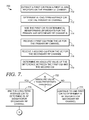
- FIG. 7 a flow diagram is depicted of an exemplary method 700 of estimating an UL SRS for a secondary RF channel associated with an eNodeB in an LTE network deploying carrier aggregation.
- the eNodeB has a primary RF channel having a primary DL channel and an associated UL channel.
- the eNodeB also has one or more secondary RF channels that only have a DL channel and not an associated UL channel.
- a first CIR is extracted from a UL SRS received from a UE on the eNodeB's primary UL channel.
- a long-term-average CIR for the primary RF channel is calculated over a first time frame. The time frame over which the long-term-average CIR is calculated may subsequently be adjusted depending on CQIs received from the UE for the primary and secondary RF channels. This will be explained in greater depth below.
- the first CIR is used to determine DL BF weights for both the primary RF channel and the secondary RF channel.
- a first CQI is received from the UE for the primary DL channel, and, at a step 718 , a second CQI is received from the UE for the secondary DL channel.
- the absolute value of the difference between the first CQI and the second CQI is determined.
- the first CIR continues to be used to determine the DL BF weights for the secondary RF channel.
- the long-term-average CIR determined at step 712 is used to determine DL BF weights for the secondary RF channel.
- the long-term-average CIR is adjustable by, for example, modifying the time frame over which the CIR is calculated or by taking into account a correction factor, delta.
- a determination is made whether the mathematical difference between the first CQI and the second CQI is greater than zero (e.g., CQI 1 ⁇ CQI 2 >0).
- the mathematical difference is greater than zero, then the long-term-average CIR is adjusted upward by an amount delta.
- the mathematical difference is less than zero (e.g., CQI 1 ⁇ CQI 2 ⁇ 0)
- the long-term-average CIR is adjusted downward by the amount delta.
- Delta may be calculated in a variety of ways.
- ⁇ is the network-configurable parameter
- ⁇ is a channel impulse response estimate based on the UL SRS
- h is the channel impulse response
- y is the received SRS sequence
- x is the transmitted SRS sequence
- n is channel noise.
- ⁇ is the network-configurable parameter used in Formula 1
- N is the sample size
- zc u ⁇ ( n ) e - j ⁇ un ⁇ ( n + 1 ) N ZC ; 0 ⁇ n ⁇ N ZC ⁇ 1, n is the sample size, u is the sequence index, and N ZC is the length of the sequence.
- x(t) is the traffic signal received at time t
- N is the sample size
- j ⁇ square root over ( ⁇ 1) ⁇
- f ⁇
- e ⁇ j2 ⁇ f ⁇ t cos(2 ⁇ f ⁇ t) ⁇ j sin(2 ⁇ f ⁇ t).
- Step 734 the adjusted long-term-average CIR calculated at steps 730 or 732 is used to determine the DL BF weights for the secondary RF channel.
- Step 734 is executed when the absolute value of the difference between the first CQI and the second CQI is greater than the predetermined threshold.
- the long-term-average CIR can also be adjusted by increasing or decreasing the time frame over which the CIR is measured.
- a predefined value such as 5
- the time frame is increased by a certain percentage.
- the time frame window may be adjusted by +/ ⁇ 5 milliseconds, +/ ⁇ 10 milliseconds, or +/ ⁇ 20 milliseconds.
- the time frame window may be adjusted to a maximum of +/ ⁇ 50%.
- the adjustment may be carried out linearly or exponentially. Any and all such aspects, and any variation thereof, are contemplated as being within the scope of the invention.
- the methods 500 , 600 and 700 can be used when more than two RF channels are aggregated on the eNodeB. For example, when there is a third RF channel that has a DL channel but lacks an associated UL channel, the CIR extracted from the UL SRS received on the primary UL channel is initially used to determine DL BF weights for the third RF channel.
- a third CQI is received from the UE for the third DL channel, and the absolute value of the difference between the first CQI and the third CQI is determined.
- the long-term-average CIR of the primary RF channel is used to determine the DL BF weights for the third RF channel.
- the first CIR continues to be used to determine DL BF weights for the third RF channel.
Landscapes
- Engineering & Computer Science (AREA)
- Signal Processing (AREA)
- Computer Networks & Wireless Communication (AREA)
- Quality & Reliability (AREA)
- Power Engineering (AREA)
- Mobile Radio Communication Systems (AREA)
Abstract
Description
-
- BF Beamforming
- CA Carrier Aggregation
- CDMA Code Division Multiple Access
- CIR Channel Impulse Response
- CQI Channel Quality Indicator
- DL Downlink
- eNodeB Evolved Node B
- GIS Geographic Information System
- 2GPP 2nd Generation Partnership Project
- 3GPP 3rd Generation Partnership Project
- GPRS General Packet Radio Service
- GSM Global System for Mobile Communications
- LTE Long-Term Evolution
- RF Radio-Frequency
- SRS Sounding Reference Signal
- TDD Time Division Duplex
- TDMA Time Division Multiple Access
- TM Transmission Mode
- UE User Equipment
- UL Uplink
- WCDMA Wideband Code Division Multiple Access
|CQIPrimary RF Channel−CQISecondary RF Channel|
Δ=|α·ĥ| 2 , ĥ=E[y−x T ], y=h*x+n (Formula 1)
Δ=α·p, p=1/NΣ n=0 N−1 x 2 [n] (Formula 2)
x[n]=e jcn zc u(mod(n,N zc)) (Formula 3)
0≦n≦NZC−1, n is the sample size, u is the sequence index, and NZC is the length of the sequence.
Δ=p, p=
Claims (20)
Priority Applications (1)
| Application Number | Priority Date | Filing Date | Title |
|---|---|---|---|
| US14/017,660 US9154284B1 (en) | 2013-09-04 | 2013-09-04 | Estimating sounding reference signals for secondary radio-frequency channels |
Applications Claiming Priority (1)
| Application Number | Priority Date | Filing Date | Title |
|---|---|---|---|
| US14/017,660 US9154284B1 (en) | 2013-09-04 | 2013-09-04 | Estimating sounding reference signals for secondary radio-frequency channels |
Publications (1)
| Publication Number | Publication Date |
|---|---|
| US9154284B1 true US9154284B1 (en) | 2015-10-06 |
Family
ID=54203915
Family Applications (1)
| Application Number | Title | Priority Date | Filing Date |
|---|---|---|---|
| US14/017,660 Active 2033-12-25 US9154284B1 (en) | 2013-09-04 | 2013-09-04 | Estimating sounding reference signals for secondary radio-frequency channels |
Country Status (1)
| Country | Link |
|---|---|
| US (1) | US9154284B1 (en) |
Cited By (5)
| Publication number | Priority date | Publication date | Assignee | Title |
|---|---|---|---|---|
| US9537547B1 (en) * | 2014-07-02 | 2017-01-03 | Sprint Communications Company L.P. | User equipment SRS selection with network node intelligence for beamforming performance improvement |
| CN106792778A (en) * | 2016-12-09 | 2017-05-31 | 北京锐安科技有限公司 | The method and device of uplink SRS signal power in a kind of measurement LTE system |
| CN107889220A (en) * | 2016-09-29 | 2018-04-06 | 华为技术有限公司 | Communication means, base station and terminal device |
| CN109076551A (en) * | 2016-04-27 | 2018-12-21 | 华为技术有限公司 | Sounding Reference Signal (SRS) Design for Cellular Time Division Duplex (TDD) mmWave Systems |
| US11310640B2 (en) * | 2019-02-20 | 2022-04-19 | Volkswagen Aktiengesellschaft | Method for vehicle-to-vehicle communication |
Citations (3)
| Publication number | Priority date | Publication date | Assignee | Title |
|---|---|---|---|---|
| US20130114767A1 (en) * | 2011-11-07 | 2013-05-09 | Electronics And Telecommunications Research Institute | Apparatus and method for enhancing channel estimation accuracy in communication system |
| US20130201912A1 (en) * | 2010-05-19 | 2013-08-08 | Interdigital Patent Holdings, Inc. | Method and apparatus for compressing channel state information based on path location information |
| US20140248917A1 (en) * | 2013-03-04 | 2014-09-04 | Qualcomm Incorporated | Apparatus and methods of frequency spectrum usage in a wireless communication system |
-
2013
- 2013-09-04 US US14/017,660 patent/US9154284B1/en active Active
Patent Citations (3)
| Publication number | Priority date | Publication date | Assignee | Title |
|---|---|---|---|---|
| US20130201912A1 (en) * | 2010-05-19 | 2013-08-08 | Interdigital Patent Holdings, Inc. | Method and apparatus for compressing channel state information based on path location information |
| US20130114767A1 (en) * | 2011-11-07 | 2013-05-09 | Electronics And Telecommunications Research Institute | Apparatus and method for enhancing channel estimation accuracy in communication system |
| US20140248917A1 (en) * | 2013-03-04 | 2014-09-04 | Qualcomm Incorporated | Apparatus and methods of frequency spectrum usage in a wireless communication system |
Cited By (11)
| Publication number | Priority date | Publication date | Assignee | Title |
|---|---|---|---|---|
| US9537547B1 (en) * | 2014-07-02 | 2017-01-03 | Sprint Communications Company L.P. | User equipment SRS selection with network node intelligence for beamforming performance improvement |
| CN109076551A (en) * | 2016-04-27 | 2018-12-21 | 华为技术有限公司 | Sounding Reference Signal (SRS) Design for Cellular Time Division Duplex (TDD) mmWave Systems |
| CN109076551B (en) * | 2016-04-27 | 2021-02-12 | 华为技术有限公司 | Design of sounding reference signal for cellular time division duplex millimeter wave system |
| US11522743B2 (en) | 2016-04-27 | 2022-12-06 | Futurewei Technologies, Inc. | Sounding reference signal (SRS) design for cellular time division duplex (TDD) mmWave systems |
| US11888665B2 (en) | 2016-04-27 | 2024-01-30 | Futurewei Technologies, Inc. | Sounding reference signal (SRS) design for cellular time division duplex (TDD) mmWave systems |
| CN107889220A (en) * | 2016-09-29 | 2018-04-06 | 华为技术有限公司 | Communication means, base station and terminal device |
| US11234148B2 (en) | 2016-09-29 | 2022-01-25 | Huawei Technologies Co., Ltd. | Communication method, base station, and terminal device |
| CN107889220B (en) * | 2016-09-29 | 2022-01-28 | 华为技术有限公司 | Communication method, base station and terminal equipment |
| CN106792778A (en) * | 2016-12-09 | 2017-05-31 | 北京锐安科技有限公司 | The method and device of uplink SRS signal power in a kind of measurement LTE system |
| CN106792778B (en) * | 2016-12-09 | 2020-02-07 | 北京锐安科技有限公司 | Method and device for measuring uplink SRS signal power in LTE system |
| US11310640B2 (en) * | 2019-02-20 | 2022-04-19 | Volkswagen Aktiengesellschaft | Method for vehicle-to-vehicle communication |
Similar Documents
| Publication | Publication Date | Title |
|---|---|---|
| JP7052058B2 (en) | Improved activation of secondary cells for carrier aggregation and dual connectivity | |
| JP6999811B2 (en) | Signal transmission methods, terminal devices, and network devices | |
| US10840984B2 (en) | Method for reporting channel state information, user equipment, and base station | |
| RU2537970C2 (en) | Power control method and apparatus | |
| EP2769517B1 (en) | Channel estimation using reference signals | |
| RU2761444C1 (en) | Method for transmission of the probing reference signal, network device and terminal device | |
| CN113302870B (en) | Method and device for reporting channel state information | |
| CN110035444B (en) | Resource determination method and device | |
| US9154284B1 (en) | Estimating sounding reference signals for secondary radio-frequency channels | |
| US12167397B2 (en) | Signal reception apparatus and method and communications system | |
| EP3048752B1 (en) | Method and apparatus for management of frequency-division-duplex and time-division-duplex carrier aggregation | |
| EP3673596B1 (en) | Method and apparatus for improving resource efficiency in a wireless communication system | |
| AU2021420388B2 (en) | Communication method and apparatus | |
| CN108781134B (en) | Method, network side device and user equipment for measuring channel state information | |
| CN104780550B (en) | A kind of interference detection method, base station and system | |
| US20150117338A1 (en) | Cyclic Channel State Information Reference Signal Configuration for New Carrier Type with Backward Compatible Segment | |
| US20140355572A1 (en) | Method and apparatus for automatic gain control for td-scdma systems | |
| WO2016071148A1 (en) | Method and apparatus for improving a time granularity when deploying a wireless system | |
| WO2019028675A1 (en) | Method and apparatus for uplink transmission in a wireless communication system | |
| EP2757751A2 (en) | Wireless communication precoder determination | |
| US9014119B2 (en) | Spectrum estimation for low-load LTE signals | |
| US20140029425A1 (en) | Method And Apparatus For Inter-Carrier Load Balancing | |
| Lee et al. | A practical channel estimation and feedback method for device-to-device communication in 3GPP LTE system | |
| US9282469B1 (en) | Increasing CINR gain in a network deploying beam forming | |
| US20200099489A1 (en) | Method and apparatus for configuring reference signal of a wireless communication system |
Legal Events
| Date | Code | Title | Description |
|---|---|---|---|
| AS | Assignment |
Owner name: SPRINT COMMUNICATIONS COMPANY L.P., KANSAS Free format text: ASSIGNMENT OF ASSIGNORS INTEREST;ASSIGNORS:PARK, SUNGKI;SCOTT, BRENT;KAZEMINEJAD, SAIED;AND OTHERS;SIGNING DATES FROM 20130823 TO 20130830;REEL/FRAME:031765/0944 |
|
| STCF | Information on status: patent grant |
Free format text: PATENTED CASE |
|
| AS | Assignment |
Owner name: DEUTSCHE BANK TRUST COMPANY AMERICAS, NEW YORK Free format text: GRANT OF FIRST PRIORITY AND JUNIOR PRIORITY SECURITY INTEREST IN PATENT RIGHTS;ASSIGNOR:SPRINT COMMUNICATIONS COMPANY L.P.;REEL/FRAME:041895/0210 Effective date: 20170203 |
|
| MAFP | Maintenance fee payment |
Free format text: PAYMENT OF MAINTENANCE FEE, 4TH YEAR, LARGE ENTITY (ORIGINAL EVENT CODE: M1551); ENTITY STATUS OF PATENT OWNER: LARGE ENTITY Year of fee payment: 4 |
|
| AS | Assignment |
Owner name: SPRINT COMMUNICATIONS COMPANY L.P., KANSAS Free format text: TERMINATION AND RELEASE OF FIRST PRIORITY AND JUNIOR PRIORITY SECURITY INTEREST IN PATENT RIGHTS;ASSIGNOR:DEUTSCHE BANK TRUST COMPANY AMERICAS;REEL/FRAME:052969/0475 Effective date: 20200401 Owner name: DEUTSCHE BANK TRUST COMPANY AMERICAS, NEW YORK Free format text: SECURITY AGREEMENT;ASSIGNORS:T-MOBILE USA, INC.;ISBV LLC;T-MOBILE CENTRAL LLC;AND OTHERS;REEL/FRAME:053182/0001 Effective date: 20200401 |
|
| AS | Assignment |
Owner name: T-MOBILE INNOVATIONS LLC, KANSAS Free format text: ASSIGNMENT OF ASSIGNORS INTEREST;ASSIGNOR:SPRINT COMMUNICATIONS COMPANY L.P.;REEL/FRAME:055604/0001 Effective date: 20210303 Owner name: T-MOBILE INNOVATIONS LLC, KANSAS Free format text: ASSIGNMENT OF ASSIGNOR'S INTEREST;ASSIGNOR:SPRINT COMMUNICATIONS COMPANY L.P.;REEL/FRAME:055604/0001 Effective date: 20210303 |
|
| AS | Assignment |
Owner name: SPRINT SPECTRUM LLC, KANSAS Free format text: RELEASE BY SECURED PARTY;ASSIGNOR:DEUTSCHE BANK TRUST COMPANY AMERICAS;REEL/FRAME:062595/0001 Effective date: 20220822 Owner name: SPRINT INTERNATIONAL INCORPORATED, KANSAS Free format text: RELEASE BY SECURED PARTY;ASSIGNOR:DEUTSCHE BANK TRUST COMPANY AMERICAS;REEL/FRAME:062595/0001 Effective date: 20220822 Owner name: SPRINT COMMUNICATIONS COMPANY L.P., KANSAS Free format text: RELEASE BY SECURED PARTY;ASSIGNOR:DEUTSCHE BANK TRUST COMPANY AMERICAS;REEL/FRAME:062595/0001 Effective date: 20220822 Owner name: SPRINTCOM LLC, KANSAS Free format text: RELEASE BY SECURED PARTY;ASSIGNOR:DEUTSCHE BANK TRUST COMPANY AMERICAS;REEL/FRAME:062595/0001 Effective date: 20220822 Owner name: CLEARWIRE IP HOLDINGS LLC, KANSAS Free format text: RELEASE BY SECURED PARTY;ASSIGNOR:DEUTSCHE BANK TRUST COMPANY AMERICAS;REEL/FRAME:062595/0001 Effective date: 20220822 Owner name: CLEARWIRE COMMUNICATIONS LLC, KANSAS Free format text: RELEASE BY SECURED PARTY;ASSIGNOR:DEUTSCHE BANK TRUST COMPANY AMERICAS;REEL/FRAME:062595/0001 Effective date: 20220822 Owner name: BOOST WORLDWIDE, LLC, KANSAS Free format text: RELEASE BY SECURED PARTY;ASSIGNOR:DEUTSCHE BANK TRUST COMPANY AMERICAS;REEL/FRAME:062595/0001 Effective date: 20220822 Owner name: ASSURANCE WIRELESS USA, L.P., KANSAS Free format text: RELEASE BY SECURED PARTY;ASSIGNOR:DEUTSCHE BANK TRUST COMPANY AMERICAS;REEL/FRAME:062595/0001 Effective date: 20220822 Owner name: T-MOBILE USA, INC., WASHINGTON Free format text: RELEASE BY SECURED PARTY;ASSIGNOR:DEUTSCHE BANK TRUST COMPANY AMERICAS;REEL/FRAME:062595/0001 Effective date: 20220822 Owner name: T-MOBILE CENTRAL LLC, WASHINGTON Free format text: RELEASE BY SECURED PARTY;ASSIGNOR:DEUTSCHE BANK TRUST COMPANY AMERICAS;REEL/FRAME:062595/0001 Effective date: 20220822 Owner name: PUSHSPRING, LLC, WASHINGTON Free format text: RELEASE BY SECURED PARTY;ASSIGNOR:DEUTSCHE BANK TRUST COMPANY AMERICAS;REEL/FRAME:062595/0001 Effective date: 20220822 Owner name: LAYER3 TV, LLC, WASHINGTON Free format text: RELEASE BY SECURED PARTY;ASSIGNOR:DEUTSCHE BANK TRUST COMPANY AMERICAS;REEL/FRAME:062595/0001 Effective date: 20220822 Owner name: IBSV LLC, WASHINGTON Free format text: RELEASE BY SECURED PARTY;ASSIGNOR:DEUTSCHE BANK TRUST COMPANY AMERICAS;REEL/FRAME:062595/0001 Effective date: 20220822 Owner name: IBSV LLC, WASHINGTON Free format text: RELEASE OF SECURITY INTEREST;ASSIGNOR:DEUTSCHE BANK TRUST COMPANY AMERICAS;REEL/FRAME:062595/0001 Effective date: 20220822 Owner name: LAYER3 TV, LLC, WASHINGTON Free format text: RELEASE OF SECURITY INTEREST;ASSIGNOR:DEUTSCHE BANK TRUST COMPANY AMERICAS;REEL/FRAME:062595/0001 Effective date: 20220822 Owner name: PUSHSPRING, LLC, WASHINGTON Free format text: RELEASE OF SECURITY INTEREST;ASSIGNOR:DEUTSCHE BANK TRUST COMPANY AMERICAS;REEL/FRAME:062595/0001 Effective date: 20220822 Owner name: T-MOBILE CENTRAL LLC, WASHINGTON Free format text: RELEASE OF SECURITY INTEREST;ASSIGNOR:DEUTSCHE BANK TRUST COMPANY AMERICAS;REEL/FRAME:062595/0001 Effective date: 20220822 Owner name: T-MOBILE USA, INC., WASHINGTON Free format text: RELEASE OF SECURITY INTEREST;ASSIGNOR:DEUTSCHE BANK TRUST COMPANY AMERICAS;REEL/FRAME:062595/0001 Effective date: 20220822 Owner name: ASSURANCE WIRELESS USA, L.P., KANSAS Free format text: RELEASE OF SECURITY INTEREST;ASSIGNOR:DEUTSCHE BANK TRUST COMPANY AMERICAS;REEL/FRAME:062595/0001 Effective date: 20220822 Owner name: BOOST WORLDWIDE, LLC, KANSAS Free format text: RELEASE OF SECURITY INTEREST;ASSIGNOR:DEUTSCHE BANK TRUST COMPANY AMERICAS;REEL/FRAME:062595/0001 Effective date: 20220822 Owner name: CLEARWIRE COMMUNICATIONS LLC, KANSAS Free format text: RELEASE OF SECURITY INTEREST;ASSIGNOR:DEUTSCHE BANK TRUST COMPANY AMERICAS;REEL/FRAME:062595/0001 Effective date: 20220822 Owner name: CLEARWIRE IP HOLDINGS LLC, KANSAS Free format text: RELEASE OF SECURITY INTEREST;ASSIGNOR:DEUTSCHE BANK TRUST COMPANY AMERICAS;REEL/FRAME:062595/0001 Effective date: 20220822 Owner name: SPRINTCOM LLC, KANSAS Free format text: RELEASE OF SECURITY INTEREST;ASSIGNOR:DEUTSCHE BANK TRUST COMPANY AMERICAS;REEL/FRAME:062595/0001 Effective date: 20220822 Owner name: SPRINT COMMUNICATIONS COMPANY L.P., KANSAS Free format text: RELEASE OF SECURITY INTEREST;ASSIGNOR:DEUTSCHE BANK TRUST COMPANY AMERICAS;REEL/FRAME:062595/0001 Effective date: 20220822 Owner name: SPRINT INTERNATIONAL INCORPORATED, KANSAS Free format text: RELEASE OF SECURITY INTEREST;ASSIGNOR:DEUTSCHE BANK TRUST COMPANY AMERICAS;REEL/FRAME:062595/0001 Effective date: 20220822 Owner name: SPRINT SPECTRUM LLC, KANSAS Free format text: RELEASE OF SECURITY INTEREST;ASSIGNOR:DEUTSCHE BANK TRUST COMPANY AMERICAS;REEL/FRAME:062595/0001 Effective date: 20220822 |
|
| MAFP | Maintenance fee payment |
Free format text: PAYMENT OF MAINTENANCE FEE, 8TH YEAR, LARGE ENTITY (ORIGINAL EVENT CODE: M1552); ENTITY STATUS OF PATENT OWNER: LARGE ENTITY Year of fee payment: 8 |