US9150756B2 - Sampling device for substance detection instrument - Google Patents
Sampling device for substance detection instrument Download PDFInfo
- Publication number
- US9150756B2 US9150756B2 US13/207,071 US201113207071A US9150756B2 US 9150756 B2 US9150756 B2 US 9150756B2 US 201113207071 A US201113207071 A US 201113207071A US 9150756 B2 US9150756 B2 US 9150756B2
- Authority
- US
- United States
- Prior art keywords
- membrane
- sampling device
- polysiloxane
- coating
- back side
- Prior art date
- Legal status (The legal status is an assumption and is not a legal conclusion. Google has not performed a legal analysis and makes no representation as to the accuracy of the status listed.)
- Active, expires
Links
- 238000005070 sampling Methods 0.000 title claims abstract description 46
- 239000000126 substance Substances 0.000 title claims abstract description 34
- 238000001514 detection method Methods 0.000 title claims abstract description 15
- 239000012528 membrane Substances 0.000 claims abstract description 58
- -1 polysiloxane Polymers 0.000 claims abstract description 33
- 229920001296 polysiloxane Polymers 0.000 claims abstract description 28
- 238000000576 coating method Methods 0.000 claims abstract description 24
- 239000011248 coating agent Substances 0.000 claims abstract description 22
- 125000000732 arylene group Chemical group 0.000 claims abstract description 18
- 239000012159 carrier gas Substances 0.000 claims abstract description 14
- 239000012530 fluid Substances 0.000 claims abstract description 11
- 238000004891 communication Methods 0.000 claims abstract description 10
- 238000012360 testing method Methods 0.000 claims abstract description 10
- 239000000463 material Substances 0.000 claims description 13
- 229920001577 copolymer Polymers 0.000 claims description 10
- 239000007789 gas Substances 0.000 claims description 10
- 238000000034 method Methods 0.000 claims description 8
- 238000004817 gas chromatography Methods 0.000 claims description 3
- 229910052710 silicon Inorganic materials 0.000 claims description 3
- 239000010703 silicon Substances 0.000 claims description 3
- 125000005647 linker group Chemical group 0.000 claims 1
- 239000000523 sample Substances 0.000 description 17
- 229920000642 polymer Polymers 0.000 description 9
- 238000004381 surface treatment Methods 0.000 description 9
- 150000001875 compounds Chemical class 0.000 description 8
- 229910052739 hydrogen Inorganic materials 0.000 description 6
- 239000001257 hydrogen Substances 0.000 description 6
- 125000001424 substituent group Chemical group 0.000 description 6
- 239000012491 analyte Substances 0.000 description 5
- KPUWHANPEXNPJT-UHFFFAOYSA-N disiloxane Chemical class [SiH3]O[SiH3] KPUWHANPEXNPJT-UHFFFAOYSA-N 0.000 description 5
- 239000000178 monomer Substances 0.000 description 5
- 125000005373 siloxane group Chemical group [SiH2](O*)* 0.000 description 5
- 0 [1*][Si]([2*])(C)[Ar][Si]([3*])([4*])OC.[5*][Si]([6*])(C)OC Chemical compound [1*][Si]([2*])(C)[Ar][Si]([3*])([4*])OC.[5*][Si]([6*])(C)OC 0.000 description 4
- 230000015572 biosynthetic process Effects 0.000 description 4
- 125000004432 carbon atom Chemical group C* 0.000 description 4
- 239000010410 layer Substances 0.000 description 4
- VYPSYNLAJGMNEJ-UHFFFAOYSA-N silicon dioxide Inorganic materials O=[Si]=O VYPSYNLAJGMNEJ-UHFFFAOYSA-N 0.000 description 4
- 238000003786 synthesis reaction Methods 0.000 description 4
- 125000000217 alkyl group Chemical group 0.000 description 3
- 230000008878 coupling Effects 0.000 description 3
- 238000010168 coupling process Methods 0.000 description 3
- 238000005859 coupling reaction Methods 0.000 description 3
- 239000000203 mixture Substances 0.000 description 3
- 238000012546 transfer Methods 0.000 description 3
- SPSSULHKWOKEEL-UHFFFAOYSA-N 2,4,6-trinitrotoluene Chemical compound CC1=C([N+]([O-])=O)C=C([N+]([O-])=O)C=C1[N+]([O-])=O SPSSULHKWOKEEL-UHFFFAOYSA-N 0.000 description 2
- BVKZGUZCCUSVTD-UHFFFAOYSA-L Carbonate Chemical compound [O-]C([O-])=O BVKZGUZCCUSVTD-UHFFFAOYSA-L 0.000 description 2
- UFHFLCQGNIYNRP-UHFFFAOYSA-N Hydrogen Chemical compound [H][H] UFHFLCQGNIYNRP-UHFFFAOYSA-N 0.000 description 2
- PXHVJJICTQNCMI-UHFFFAOYSA-N Nickel Chemical compound [Ni] PXHVJJICTQNCMI-UHFFFAOYSA-N 0.000 description 2
- XUIMIQQOPSSXEZ-UHFFFAOYSA-N Silicon Chemical compound [Si] XUIMIQQOPSSXEZ-UHFFFAOYSA-N 0.000 description 2
- 125000004429 atom Chemical group 0.000 description 2
- 238000011109 contamination Methods 0.000 description 2
- 238000013461 design Methods 0.000 description 2
- UQXKXGWGFRWILX-UHFFFAOYSA-N ethylene glycol dinitrate Chemical compound O=N(=O)OCCON(=O)=O UQXKXGWGFRWILX-UHFFFAOYSA-N 0.000 description 2
- 239000002360 explosive Substances 0.000 description 2
- 229910052736 halogen Inorganic materials 0.000 description 2
- 150000002367 halogens Chemical class 0.000 description 2
- 230000005661 hydrophobic surface Effects 0.000 description 2
- 238000004949 mass spectrometry Methods 0.000 description 2
- 230000037361 pathway Effects 0.000 description 2
- 125000001997 phenyl group Chemical group [H]C1=C([H])C([H])=C(*)C([H])=C1[H] 0.000 description 2
- 239000000015 trinitrotoluene Substances 0.000 description 2
- OKTJSMMVPCPJKN-UHFFFAOYSA-N Carbon Chemical compound [C] OKTJSMMVPCPJKN-UHFFFAOYSA-N 0.000 description 1
- VYZAMTAEIAYCRO-UHFFFAOYSA-N Chromium Chemical compound [Cr] VYZAMTAEIAYCRO-UHFFFAOYSA-N 0.000 description 1
- SNIOPGDIGTZGOP-UHFFFAOYSA-N Nitroglycerin Chemical compound [O-][N+](=O)OCC(O[N+]([O-])=O)CO[N+]([O-])=O SNIOPGDIGTZGOP-UHFFFAOYSA-N 0.000 description 1
- 239000000006 Nitroglycerin Substances 0.000 description 1
- 239000004952 Polyamide Substances 0.000 description 1
- BLRPTPMANUNPDV-UHFFFAOYSA-N Silane Chemical group [SiH4] BLRPTPMANUNPDV-UHFFFAOYSA-N 0.000 description 1
- 230000004075 alteration Effects 0.000 description 1
- 238000004458 analytical method Methods 0.000 description 1
- 238000002048 anodisation reaction Methods 0.000 description 1
- 229920003235 aromatic polyamide Polymers 0.000 description 1
- 125000003118 aryl group Chemical group 0.000 description 1
- 239000012472 biological sample Substances 0.000 description 1
- 230000005540 biological transmission Effects 0.000 description 1
- 229920001400 block copolymer Polymers 0.000 description 1
- 230000001680 brushing effect Effects 0.000 description 1
- 239000002041 carbon nanotube Substances 0.000 description 1
- 229910021393 carbon nanotube Inorganic materials 0.000 description 1
- 238000005229 chemical vapour deposition Methods 0.000 description 1
- 229910052804 chromium Inorganic materials 0.000 description 1
- 239000011651 chromium Substances 0.000 description 1
- 239000000470 constituent Substances 0.000 description 1
- 230000002939 deleterious effect Effects 0.000 description 1
- 238000007598 dipping method Methods 0.000 description 1
- 239000003814 drug Substances 0.000 description 1
- 229940079593 drug Drugs 0.000 description 1
- 239000008393 encapsulating agent Substances 0.000 description 1
- 238000005516 engineering process Methods 0.000 description 1
- 125000004185 ester group Chemical group 0.000 description 1
- 150000002148 esters Chemical class 0.000 description 1
- 239000004744 fabric Substances 0.000 description 1
- 239000000835 fiber Substances 0.000 description 1
- 239000011152 fibreglass Substances 0.000 description 1
- 239000000945 filler Substances 0.000 description 1
- 125000003709 fluoroalkyl group Chemical group 0.000 description 1
- 229920002313 fluoropolymer Polymers 0.000 description 1
- 239000004811 fluoropolymer Substances 0.000 description 1
- 125000000524 functional group Chemical group 0.000 description 1
- 239000011521 glass Substances 0.000 description 1
- 229960003711 glyceryl trinitrate Drugs 0.000 description 1
- 238000010438 heat treatment Methods 0.000 description 1
- 230000010354 integration Effects 0.000 description 1
- 150000002500 ions Chemical class 0.000 description 1
- UQSXHKLRYXJYBZ-UHFFFAOYSA-N iron oxide Inorganic materials [Fe]=O UQSXHKLRYXJYBZ-UHFFFAOYSA-N 0.000 description 1
- 239000011159 matrix material Substances 0.000 description 1
- 230000007246 mechanism Effects 0.000 description 1
- 229910052751 metal Inorganic materials 0.000 description 1
- 239000002184 metal Substances 0.000 description 1
- 150000002739 metals Chemical class 0.000 description 1
- 125000002496 methyl group Chemical group [H]C([H])([H])* 0.000 description 1
- 229910052759 nickel Inorganic materials 0.000 description 1
- NDLPOXTZKUMGOV-UHFFFAOYSA-N oxo(oxoferriooxy)iron hydrate Chemical compound O.O=[Fe]O[Fe]=O NDLPOXTZKUMGOV-UHFFFAOYSA-N 0.000 description 1
- 238000005498 polishing Methods 0.000 description 1
- 229920002647 polyamide Polymers 0.000 description 1
- 239000011148 porous material Substances 0.000 description 1
- 238000012545 processing Methods 0.000 description 1
- 239000010453 quartz Substances 0.000 description 1
- 230000009257 reactivity Effects 0.000 description 1
- 238000005096 rolling process Methods 0.000 description 1
- 239000000377 silicon dioxide Substances 0.000 description 1
- 229910052990 silicon hydride Inorganic materials 0.000 description 1
- 238000001228 spectrum Methods 0.000 description 1
- 229910001256 stainless steel alloy Inorganic materials 0.000 description 1
- 238000006467 substitution reaction Methods 0.000 description 1
- 239000002344 surface layer Substances 0.000 description 1
- 231100000331 toxic Toxicity 0.000 description 1
- 230000002588 toxic effect Effects 0.000 description 1
- 238000007740 vapor deposition Methods 0.000 description 1
Images


Classifications
-
- C—CHEMISTRY; METALLURGY
- C09—DYES; PAINTS; POLISHES; NATURAL RESINS; ADHESIVES; COMPOSITIONS NOT OTHERWISE PROVIDED FOR; APPLICATIONS OF MATERIALS NOT OTHERWISE PROVIDED FOR
- C09D—COATING COMPOSITIONS, e.g. PAINTS, VARNISHES OR LACQUERS; FILLING PASTES; CHEMICAL PAINT OR INK REMOVERS; INKS; CORRECTING FLUIDS; WOODSTAINS; PASTES OR SOLIDS FOR COLOURING OR PRINTING; USE OF MATERIALS THEREFOR
- C09D183/00—Coating compositions based on macromolecular compounds obtained by reactions forming in the main chain of the macromolecule a linkage containing silicon, with or without sulfur, nitrogen, oxygen, or carbon only; Coating compositions based on derivatives of such polymers
- C09D183/14—Coating compositions based on macromolecular compounds obtained by reactions forming in the main chain of the macromolecule a linkage containing silicon, with or without sulfur, nitrogen, oxygen, or carbon only; Coating compositions based on derivatives of such polymers in which at least two but not all the silicon atoms are connected by linkages other than oxygen atoms
-
- G—PHYSICS
- G01—MEASURING; TESTING
- G01N—INVESTIGATING OR ANALYSING MATERIALS BY DETERMINING THEIR CHEMICAL OR PHYSICAL PROPERTIES
- G01N1/00—Sampling; Preparing specimens for investigation
- G01N1/02—Devices for withdrawing samples
-
- C—CHEMISTRY; METALLURGY
- C08—ORGANIC MACROMOLECULAR COMPOUNDS; THEIR PREPARATION OR CHEMICAL WORKING-UP; COMPOSITIONS BASED THEREON
- C08G—MACROMOLECULAR COMPOUNDS OBTAINED OTHERWISE THAN BY REACTIONS ONLY INVOLVING UNSATURATED CARBON-TO-CARBON BONDS
- C08G77/00—Macromolecular compounds obtained by reactions forming a linkage containing silicon with or without sulfur, nitrogen, oxygen or carbon in the main chain of the macromolecule
- C08G77/48—Macromolecular compounds obtained by reactions forming a linkage containing silicon with or without sulfur, nitrogen, oxygen or carbon in the main chain of the macromolecule in which at least two but not all the silicon atoms are connected by linkages other than oxygen atoms
- C08G77/50—Macromolecular compounds obtained by reactions forming a linkage containing silicon with or without sulfur, nitrogen, oxygen or carbon in the main chain of the macromolecule in which at least two but not all the silicon atoms are connected by linkages other than oxygen atoms by carbon linkages
- C08G77/52—Macromolecular compounds obtained by reactions forming a linkage containing silicon with or without sulfur, nitrogen, oxygen or carbon in the main chain of the macromolecule in which at least two but not all the silicon atoms are connected by linkages other than oxygen atoms by carbon linkages containing aromatic rings
-
- G—PHYSICS
- G01—MEASURING; TESTING
- G01N—INVESTIGATING OR ANALYSING MATERIALS BY DETERMINING THEIR CHEMICAL OR PHYSICAL PROPERTIES
- G01N1/00—Sampling; Preparing specimens for investigation
- G01N1/02—Devices for withdrawing samples
- G01N2001/028—Sampling from a surface, swabbing, vaporising
-
- Y—GENERAL TAGGING OF NEW TECHNOLOGICAL DEVELOPMENTS; GENERAL TAGGING OF CROSS-SECTIONAL TECHNOLOGIES SPANNING OVER SEVERAL SECTIONS OF THE IPC; TECHNICAL SUBJECTS COVERED BY FORMER USPC CROSS-REFERENCE ART COLLECTIONS [XRACs] AND DIGESTS
- Y10—TECHNICAL SUBJECTS COVERED BY FORMER USPC
- Y10T—TECHNICAL SUBJECTS COVERED BY FORMER US CLASSIFICATION
- Y10T428/00—Stock material or miscellaneous articles
- Y10T428/249921—Web or sheet containing structurally defined element or component
- Y10T428/249953—Composite having voids in a component [e.g., porous, cellular, etc.]
- Y10T428/249987—With nonvoid component of specified composition
- Y10T428/249991—Synthetic resin or natural rubbers
Definitions
- TICs toxic industrial compounds
- illegal drugs drugs
- explosive compounds or chemical or biological weapons or substances.
- Some substances have a fairly high volatility.
- Many TICs have ambient temperature vapor pressures greater than 0.5 T (mmHg).
- others for example various explosives such as nitroglycerin, trinitrotoluene (TNT) and ethylene glycol dinitrate (EGDN), have ambient temperature vapor pressures below 0.05 T.
- mass spectrometry has long been used to accurately determine the presence of initially unknown chemical and biological samples.
- a sample is vaporized for transport via gas phase flow to the analyzer and ionized, with the resulting ions being measured to determine a mass to charge ratio spectrum which is, in turn, used to identify the basic constituents of the original sample.
- Bruker Daltonics manufactures portable mass spectrometers such as the MM series and the EM series. With some mass spectrometers, a sample to be tested is collected and placed in a test chamber, where it is exposed to heat and a carrier gas to volatilize and transport molecules to a mass spectrometer detection unit.
- Other mass spectrometers such as Bruker Daltonics MM1 and MM2 models, utilize a sampling head or probe that is brought into contact or proximity with a surface to capture volatilized molecules from the surface and transport them to a substance detector such as a mass spectrometer.
- sampling heads or probes have been proposed in the art, see U.S. Pat. No. 4,433,982, U.S. Pat. No. 4,541,268, and/or U.S. Pat. No. 5,517,026.
- Such sampling heads utilize a membrane that is permeable to the volatile molecules of interest, and apply heat to the membrane when it is placed in contact or proximity to the surface being tested in order to assist in volatilization of the molecules so that they diffuse into the membrane.
- a carrier gas on the back side of the membrane then carries the volatile molecules to a substance detector such as a mass spectrometer.
- sampling devices that are capable operating under a wide range of operating conditions and/or for sampling for the presence of a wide range of compounds, including both compounds of low volatility that require substantial heating to collect and compound of high volatility that are more effectively captured via whole air sampling.
- a sampling device for a substance detection instrument includes
- a membrane comprising a porous support having a coating thereon, the coating comprising a carborane polysiloxane or an arylene polysiloxane, the membrane having a front side configured to be placed in contact with a test sample and a back side;
- sample line having an inlet proximate to the back side of the membrane and an outlet in fluid communication with a substance detector;
- a source of carrier gas in fluid communication with the back side of the membrane and the sample line inlet.
- the sampling device further includes a heater disposed to heat the membrane.
- a membrane for a sampling device includes a porous support having a coating thereon, the coating including a carborane polysiloxane or an arylene polysiloxane.
- a method of sampling a material for the presence of substances comprises placing a sampling device in contact with the material, the sampling device comprising:
- a membrane comprising a porous support having a coating thereon, said coating comprising a carborane polysiloxane or an arylene polysiloxane, said membrane having a front side configured to be placed in contact with a test sample and a back side;
- sample line having an inlet proximate to the back side of the membrane and an outlet in fluid communication with a substance detector;
- a source of carrier gas in fluid communication with the back side of the membrane and the sample line inlet.
- FIG. 1 depicts a schematic representation of a sampling device for a substance detection instrument
- FIG. 2 depicts a schematic representation of an alternative embodiment of a sampling device for a substance detection instrument
- FIG. 3 depicts a schematic representation of a membrane for use in a sampling device for a substance detection instrument.
- a simplified sampling device is schematically shown in an exploded cross-sectional view in FIG. 1 , in which a sampling device 10 has a housing 12 having a threaded coupling or other similar attachment feature 14 .
- a membrane retainer 16 having an opening 18 disposed therein is disposed over the housing 12 such that threaded coupling 20 on the retainer engages with threaded coupling 14 on the housing to secure the membrane retainer to the housing 12 .
- Membrane 22 comprising a porous support having a coating thereon is supported by a membrane support ring 24 to maintain a carrier gas flow gap between the membrane 22 and the housing 12 , and a sample transfer line 26 is disposed in the housing having an inlet 28 that is disposed proximate to the upper (rear) surface of the membrane 22 and an outlet (not shown) that leads to a substance detector (not shown) such as a mass spectrometer.
- a vacuum is drawn in the sample transfer line 26 by a pump, diaphragm, or other suitable gas transfer mechanism to draw sample gas from the inlet 28 to provide test gas to the substance detector. This creates a membrane sweep flow of ambient gas (e.g., air) drawn along the path shown in FIG.
- ambient gas e.g., air
- porous support 32 having coating 34 thereon.
- the porous support can be fabricated from any sort of inert material, including but not limited to metals (e.g., nickel, chromium, stainless steel alloys such as SS304, SS306, SS316), quartz, glass, fiberglass, cloths composed of carbon nanotube fibers, polymers (e.g., fluoropolymers, polyamides, aramids), and the like as are known in the art and may be formed from woven clothes or sintered disks.
- metals e.g., nickel, chromium, stainless steel alloys such as SS304, SS306, SS316
- quartz glass
- fiberglass cloths composed of carbon nanotube fibers
- polymers e.g., fluoropolymers, polyamides, aramids
- the support is porous, and in an exemplary embodiment is a mesh support having mesh opening sizes ranging from 2 ⁇ m to 25 ⁇ m, more specifically 4 ⁇ m to 5 ⁇ m.
- the thickness of the support can vary depending on the specific design requirements and the properties of the coatings and the molecules being tested for, but can generally range from 50 ⁇ m to 205 ⁇ m. In the case of a sintered disk support, mechanical requirements would necessitate a support thickness of 1588 ⁇ 794 ⁇ m, though the membrane material per se would be the same thickness as if a wire cloth support were used.
- the support prior to applying the arylene or carborane siloxane coating, is surface treated to provide a coating comprising silicon or other inert surface layers such as silica (SiO 2 ), substituted silica, siloxane oligomers, and the like, any of which may be substituted with functional groups (e.g., alkyl, fluoroalkyl) to provide desired levels of inertness and/or hydrophobicity.
- functional groups e.g., alkyl, fluoroalkyl
- Such surface treatments can improve the adhesion and integration of the siloxane coating, as well as modifying the characteristics of the membrane, e.g., hydrophobicity.
- Such surface treatments are known in the art, and generally involve applying silicon-containing surface coatings (e.g., carboxysilicons) using vapor deposition techniques such as chemical vapor deposition of silicon hydride gas.
- Other surface treatments include but are not limited to electropolishing (e.g., Summa® polishing) or anodization.
- Exemplary surface treatment techniques and compositions are disclosed, for example, in U.S. Pat. Nos. 6,444,326, 6,511,760, 7,867,627, and 7,070,833, the disclosures of which are incorporated herein by reference in their entirety.
- Surface-treatment processing is commercially available from suppliers such as Silcotek of Bellefonte, Pa.
- a hydrophobic surface treatment such as Silcotek's DursanTM surface treatment is utilized.
- a hydrophobic surface treatment such as Silcotek's DursanTM surface treatment is utilized in conjunction with the above-described exemplary embodiment where portion(s) of the support are not coated with the siloxane coating in order to provide a flow path for carrier gas.
- Surface treated supports of various morphologies are commercially available from suppliers such as Restek of Bellefonte, Pa.
- the sampling device's membrane is a porous support coated with a layer comprising an arylene polysiloxane.
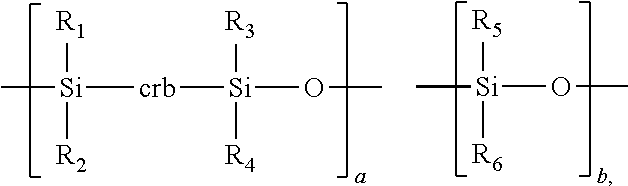
- Arylene polysiloxanes are well-known in the polymer art, and include both arylene groups and siloxane groups in a polymer backbone. Arylene polysiloxanes can be characterized by the formula (I):
- R 1 , R 2 , R 3 , R 4 , R 5 , and R 6 each independently represents an organic radical
- Ar represents a divalent arylene radical
- a represents 20 to 80 mole %, more specifically from 40 to 60 mole %
- b represents 80 to 20 mole %, more specifically from 60 to 40 mole %.
- Exemplary groups for R 1 -R 6 can include substituted or unsubstituted alkyl of 1 to 6 carbon atoms and substituted or unsubstituted aryl of 6 to 20 carbon atoms.
- each of R 1 -R 6 is unsubstituted alkyl of 1 to 4 carbon atoms, and in a still more specific exemplary embodiment each of R 1 -R 6 is a methyl group.
- a divalent arylene radical includes any divalent radical comprising divalent arylene, including compound divalent radicals such as alkylenearylene.
- Exemplary groups for Ar include substituted or unsubstituted arylene (including alkylenearylene) of 6-20 carbon atoms.
- 5,346,980 discloses arylene polysiloxanes where Ar includes 1 to 3 rings that can be fused or joined by a covalent bond or —O— linkage, an ester linkage, a carbonate linkage, an —Si(R) 2 — linkage.
- Ar is divalent phenyl.
- Ar is a 1,4-divalent phenyl.
- any of the R 1 -R 6 and Ar groups can be substituted with functional or non-functional substituents, including but not limited to unsaturated C—C double bonds, halogen, oxirane, hydroxyl, and the like.
- terminal silarylene and siloxane groups on the copolymer molecule can provide an active hydrogen (either a silyl hydrogen or siloxyl hydrogen) for attaching functional or non-functional substituents.
- the silarylene and siloxane groups in the above formula can be incorporated into the co-polymer in any pattern, including as random repeat units, or in blocks of from 2-100, more specifically from 2-50, which may themselves be blocks of a single monomer or blocks containing different monomers in either a random or block pattern.
- a and b add up to 100% including the molecular weight of any terminal atoms or groups; however, in some exemplary embodiments, other comonomers may be included so that a and b add up to less than 100%. In a more specific exemplary embodiment, a and b add up to 90-100%.
- Other co-monomers or block co-polymers can be included in co-polymer through, for example, through terminal ester or carbonate linkages to a silarylene or siloxane group.
- Various ratios of a:b may be utilized in the co-polymer. In some exemplary embodiments, the a:b ratio varies from 1.25:1 to 1:1.25, more specifically 1.1:1 to 1:1.1.
- the sampling device's membrane is a porous support coated with a layer comprising an carborane polysiloxane.
- Carborane polysiloxanes are well-known in the polymer art, and include both carborane groups and siloxane groups in a polymer backbone. Carborane polysiloxanes can be characterized by the formula (II):
- a divalent carborane radical includes any divalent radical comprising divalent carborane, including compound divalent radicals such as alkylene-carborane-alkylene.
- Exemplary carborane groups include known carboranes such as 1,7-decacarborane, 1,12-decacarborane, 1,10-octacarborane, 1,6-octacarborane, 2,4-pentacarborane, 1,6-tetracarborane, 9-alkyl-1,7-decacarborane, 9,10-dialkyl-1,7-decacarborane, 2-alkyl-1,12-decacarborane, 2-alkyl-1,10-octacarborane, 8-alkyl-1,6-octacarborane, decachloro-1,7-decacarborane, decachloro-1,12-decacarborane, octachloro-1,10-octacarborane, decafluoro-1,7-decacarborane, decafluoro-1,12-decacarborane, octaflu
- any of the R 1 -R 6 and crb groups can be substituted with functional or non-functional substituents, including but not limited to unsaturated C—C double bonds, halogen, oxirane, hydroxyl, and the like.
- terminal groups on the copolymer molecule can provide an active hydrogen (either a silyl hydrogen or siloxyl hydrogen) for attaching functional or non-functional substituents.
- the groups in the above formula can be incorporated into the co-polymer in any pattern, including as random repeat units, or in blocks of from 2-100, more specifically from 2-50, which may themselves be blocks of a single monomer or blocks containing different monomers in either a random or block pattern.
- a and b add up to 100% including the molecular weight of any terminal atoms or groups; however, in some exemplary embodiments, other comonomers may be included so that a and b add up to less than 100%.
- Further exemplary embodiments, including substituents on polymers, synthesis techniques, and the like are disclosed in U.S. Pat. Nos. 4,145,504, 4,208,492, 4,235,987, 5,208,310, and US 2005/0171317, the disclosures of each of which is incorporated herein by reference.
- Carborane siloxane and arylene siloxane polymers useful in the embodiments described herein can have molecular weights that range from 3000 to 125000, more specifically from 6000 to 25000, hardness values less than 100 (Shore A), and kinematic viscosity after curing of greater than or equal to 1000 cSt.
- a layer of arylene polysiloxane or carborane polysiloxane can be applied as 2-part curable fluid composition to the porous support using any conventional coating technique such as brushing, rolling, dipping, and the like, and then cured.
- Typical curing conditions can vary depending on the specific materials involved, but in exemplary embodiments can range from 2 to 6 hours at elevated temperatures (e.g., 50-60° C.) to greater than 70 hours at room temperature.
- the layer should be sufficient to fill or bridge over the pores or mesh openings of the porous support, and can range from 25 ⁇ m to 300 ⁇ m thick, more specifically 50 ⁇ m to 200 ⁇ m.
- the sampling device described herein can be used with any type detection device that is capable of detecting volatile molecules in a carrier gas sample or stream, including mass spectrometers or gas chromatographs, including devices with combined mass spectrometry and gas chromatography functions.
- detection devices including various features and variations thereon, are well-known and are further described in Robert Grob & Eugene Barry, Modern Practice of Chromatography—Fourth Ed ., John Wiley & Sons, 2004, the disclosure of which is incorporated herein by reference in its entirety. Further detailed disclosure of such detection devices is not warranted, because the sampling device described herein is not limited to use with any particular type or design of detection device.
Landscapes
- Chemical & Material Sciences (AREA)
- Life Sciences & Earth Sciences (AREA)
- Health & Medical Sciences (AREA)
- Analytical Chemistry (AREA)
- Materials Engineering (AREA)
- Wood Science & Technology (AREA)
- Organic Chemistry (AREA)
- Physics & Mathematics (AREA)
- Chemical Kinetics & Catalysis (AREA)
- Engineering & Computer Science (AREA)
- Biochemistry (AREA)
- General Health & Medical Sciences (AREA)
- General Physics & Mathematics (AREA)
- Immunology (AREA)
- Pathology (AREA)
- Sampling And Sample Adjustment (AREA)
Abstract
-
- a membrane comprising a porous support having a coating thereon, the coating comprising a carborane polysiloxane or an arylene polysiloxane, the membrane having a front side configured to be placed in contact with a test sample and a back side;
- a sample line having an inlet proximate to the back side of the membrane and an outlet in fluid communication with a substance detector; and
- a source of carrier gas in fluid communication with the back side of the membrane and the sample line inlet.
Description

wherein R1, R2, R3, R4, R5, and R6 each independently represents an organic radical, Ar represents a divalent arylene radical, a represents 20 to 80 mole %, more specifically from 40 to 60 mole %, and b represents 80 to 20 mole %, more specifically from 60 to 40 mole %. Exemplary groups for R1-R6 can include substituted or unsubstituted alkyl of 1 to 6 carbon atoms and substituted or unsubstituted aryl of 6 to 20 carbon atoms. In a more specific exemplary embodiment each of R1-R6 is unsubstituted alkyl of 1 to 4 carbon atoms, and in a still more specific exemplary embodiment each of R1-R6 is a methyl group. As used herein in the definition of Ar, a divalent arylene radical includes any divalent radical comprising divalent arylene, including compound divalent radicals such as alkylenearylene. Exemplary groups for Ar include substituted or unsubstituted arylene (including alkylenearylene) of 6-20 carbon atoms. U.S. Pat. No. 5,346,980 (the disclosure of which is incorporated herein by reference in its entirety) discloses arylene polysiloxanes where Ar includes 1 to 3 rings that can be fused or joined by a covalent bond or —O— linkage, an ester linkage, a carbonate linkage, an —Si(R)2— linkage. In a more specific exemplary embodiment, Ar is divalent phenyl. In another specific exemplary embodiment, Ar is a 1,4-divalent phenyl. Depending on available synthesis pathways, any of the R1-R6 and Ar groups can be substituted with functional or non-functional substituents, including but not limited to unsaturated C—C double bonds, halogen, oxirane, hydroxyl, and the like. Also, terminal silarylene and siloxane groups on the copolymer molecule can provide an active hydrogen (either a silyl hydrogen or siloxyl hydrogen) for attaching functional or non-functional substituents. The silarylene and siloxane groups in the above formula can be incorporated into the co-polymer in any pattern, including as random repeat units, or in blocks of from 2-100, more specifically from 2-50, which may themselves be blocks of a single monomer or blocks containing different monomers in either a random or block pattern. In a further exemplary embodiment, a and b add up to 100% including the molecular weight of any terminal atoms or groups; however, in some exemplary embodiments, other comonomers may be included so that a and b add up to less than 100%. In a more specific exemplary embodiment, a and b add up to 90-100%. Other co-monomers or block co-polymers can be included in co-polymer through, for example, through terminal ester or carbonate linkages to a silarylene or siloxane group. Various ratios of a:b may be utilized in the co-polymer. In some exemplary embodiments, the a:b ratio varies from 1.25:1 to 1:1.25, more specifically 1.1:1 to 1:1.1. Further exemplary embodiments, including substituents on polymers, synthesis techniques, and the like are disclosed in U.S. Pat. Nos. 3,167,528, 3,959,403, US 2002/0013441 A1, and U.S. Stat. Inv. Reg. H1612, the disclosures of which are incorporated herein by reference in their entirety, and the above-referenced U.S. Pat. No. 5,346,980. Commercially available arylene polysiloxanes include DCS-8024 (silethylphenylene)/(dimethylsiloxane) copolymer available from Gelest, Inc. of Morrisville, Pa., and Gelest OE™ 43, a 2-part silicone RTV encapsulant of a (silethylphenylene)(dimethylsiloxane) copolymer in a 1:1 kit, also available from Gelest, Inc.

wherein R1, R2, R3, R4, R5, and R6, a, and b are as defined above, and crb represents a divalent carborane radical. As used herein in the definition of crb, a divalent carborane radical includes any divalent radical comprising divalent carborane, including compound divalent radicals such as alkylene-carborane-alkylene. Exemplary carborane groups include known carboranes such as 1,7-decacarborane, 1,12-decacarborane, 1,10-octacarborane, 1,6-octacarborane, 2,4-pentacarborane, 1,6-tetracarborane, 9-alkyl-1,7-decacarborane, 9,10-dialkyl-1,7-decacarborane, 2-alkyl-1,12-decacarborane, 2-alkyl-1,10-octacarborane, 8-alkyl-1,6-octacarborane, decachloro-1,7-decacarborane, decachloro-1,12-decacarborane, octachloro-1,10-octacarborane, decafluoro-1,7-decacarborane, decafluoro-1,12-decacarborane, octafluoro-1,10-octacarborane, or mixtures thereof. Depending on available synthesis pathways, any of the R1-R6 and crb groups can be substituted with functional or non-functional substituents, including but not limited to unsaturated C—C double bonds, halogen, oxirane, hydroxyl, and the like. Also, terminal groups on the copolymer molecule can provide an active hydrogen (either a silyl hydrogen or siloxyl hydrogen) for attaching functional or non-functional substituents. The groups in the above formula can be incorporated into the co-polymer in any pattern, including as random repeat units, or in blocks of from 2-100, more specifically from 2-50, which may themselves be blocks of a single monomer or blocks containing different monomers in either a random or block pattern. In a further exemplary embodiment, a and b add up to 100% including the molecular weight of any terminal atoms or groups; however, in some exemplary embodiments, other comonomers may be included so that a and b add up to less than 100%. Further exemplary embodiments, including substituents on polymers, synthesis techniques, and the like are disclosed in U.S. Pat. Nos. 4,145,504, 4,208,492, 4,235,987, 5,208,310, and US 2005/0171317, the disclosures of each of which is incorporated herein by reference.
Claims (17)

Priority Applications (2)
| Application Number | Priority Date | Filing Date | Title |
|---|---|---|---|
| US13/207,071 US9150756B2 (en) | 2011-08-10 | 2011-08-10 | Sampling device for substance detection instrument |
| DE201210209656 DE102012209656A1 (en) | 2011-08-10 | 2012-06-08 | Sampling device for substance detection device |
Applications Claiming Priority (1)
| Application Number | Priority Date | Filing Date | Title |
|---|---|---|---|
| US13/207,071 US9150756B2 (en) | 2011-08-10 | 2011-08-10 | Sampling device for substance detection instrument |
Publications (2)
| Publication Number | Publication Date |
|---|---|
| US20130036836A1 US20130036836A1 (en) | 2013-02-14 |
| US9150756B2 true US9150756B2 (en) | 2015-10-06 |
Family
ID=47595745
Family Applications (1)
| Application Number | Title | Priority Date | Filing Date |
|---|---|---|---|
| US13/207,071 Active 2033-09-11 US9150756B2 (en) | 2011-08-10 | 2011-08-10 | Sampling device for substance detection instrument |
Country Status (2)
| Country | Link |
|---|---|
| US (1) | US9150756B2 (en) |
| DE (1) | DE102012209656A1 (en) |
Families Citing this family (5)
| Publication number | Priority date | Publication date | Assignee | Title |
|---|---|---|---|---|
| DE102013001163B3 (en) * | 2013-01-24 | 2014-04-30 | Chemin Gmbh | Grid probe for measuring deposit-forming components in gas streams in boilers of incinerators, has probe body, which is designed as pipe, where pipe has device for heating or cooling interior of grid probe or grid |
| EP3543304B1 (en) * | 2018-03-19 | 2020-08-05 | ABCR Laboratorios, S.L. | Organofunctional siloxanes, method for its preparation and use for the treatment of fillers and surfaces |
| CN111812344B (en) * | 2020-07-07 | 2023-09-29 | 清华大学深圳国际研究生院 | Membrane sample injection device and sample injection method for gas detection |
| US11619571B2 (en) * | 2020-11-27 | 2023-04-04 | Kontrol Energy Corp. | Collection chamber for an air sampling system |
| CN114813461B (en) * | 2022-03-18 | 2025-09-26 | 中国船舶重工集团公司第七二五研究所 | A method for testing the volume density of porous and complex-shaped materials |
Citations (25)
| Publication number | Priority date | Publication date | Assignee | Title |
|---|---|---|---|---|
| US3671489A (en) | 1969-12-15 | 1972-06-20 | Singer Co | Polysiloxane copolymers derived from the carborane-silicon phthalocyanine monomer |
| US3959403A (en) | 1975-03-31 | 1976-05-25 | General Electric Company | Process for making silarylenesilanediol, silarylenesiloxanediol and silarylenesiloxane-polydiorganosiloxane block copolymers |
| US4145504A (en) | 1975-06-20 | 1979-03-20 | Union Carbide Corporation | High temperature carborane-siloxane elastomers intermediate polymeric products and process for preparation |
| US4208492A (en) | 1977-12-30 | 1980-06-17 | Union Carbide Corporation | High molecular weight carborane-siloxane block copolymers and method for their preparation |
| US4235987A (en) | 1979-05-04 | 1980-11-25 | Union Carbide Corporation | Method for producing carborane-siloxane polymers directly from carborane |
| US4433982A (en) | 1980-03-10 | 1984-02-28 | Bruker-Franzen Analytik Gmbh | Input head of a measuring or identification system for chemical agents |
| US4444662A (en) * | 1979-10-22 | 1984-04-24 | Applied Membrane Technology, Inc. | Microporous laminate |
| US4541268A (en) | 1981-09-23 | 1985-09-17 | Bruker-Franzen Analytik Gmbh | Method and device for the sampling of trace elements in gases, liquids, solids or in surface layers |
| US5019139A (en) | 1989-12-22 | 1991-05-28 | The Dow Chemical Company | Valve membrane combination |
| US5208310A (en) | 1991-12-16 | 1993-05-04 | Hughes Aircraft Company | Method for preparation of very high molecular weight polycarborane siloxanes |
| US5212991A (en) | 1989-06-09 | 1993-05-25 | Proengin S.A. | Portable, self-contained equipment for the in situ analysis of a liquid or solid substance |
| US5324938A (en) * | 1991-10-08 | 1994-06-28 | Fraunhofer- Gesellschft Zur Forderung Der Angwandten Forschung E. V. | Method and apparatus for detecting strippable substances in liquids |
| US5346980A (en) | 1992-04-14 | 1994-09-13 | Minnesota Mining And Manufacturing Company | Crosslinkable silarylene-siloxane copolymers |
| US5448062A (en) * | 1993-08-30 | 1995-09-05 | Mims Technology Development Co. | Analyte separation process and apparatus |
| US5517026A (en) | 1995-01-20 | 1996-05-14 | The United States Of America As Represented By The Secretary Of The Army | On-the-move surface sampling head for a mass spectrometer |
| USH1612H (en) | 1993-08-02 | 1996-11-05 | The United States Of America As Represented By The Secretary Of The Navy | Method for making silarylene-siloxane polymers |
| US20020013441A1 (en) | 2000-06-23 | 2002-01-31 | Wacker-Chemie Gmbh | Process for the preparation of silarylenesiloxane-diorganosiloxane copolymers |
| US6444326B1 (en) | 1999-03-05 | 2002-09-03 | Restek Corporation | Surface modification of solid supports through the thermal decomposition and functionalization of silanes |
| US6511760B1 (en) | 1998-02-27 | 2003-01-28 | Restek Corporation | Method of passivating a gas vessel or component of a gas transfer system using a silicon overlay coating |
| US20040259265A1 (en) * | 2002-09-27 | 2004-12-23 | Ulrich Bonne | Phased micro analyzer IV |
| US20050171317A1 (en) | 2004-02-03 | 2005-08-04 | Keller Teddy M. | Synthesis of elastomeric carborane-siloxanes by hydrosilation reactions |
| US7070833B2 (en) | 2003-03-05 | 2006-07-04 | Restek Corporation | Method for chemical vapor deposition of silicon on to substrates for use in corrosive and vacuum environments |
| US7385191B1 (en) | 2004-12-01 | 2008-06-10 | Pacific Environmental Technologies, Llc | High pressure membrane introduction for a mass spectrometer |
| US7579587B2 (en) | 2006-01-13 | 2009-08-25 | Vancouver Island University | Thermally assisted membrane introduction mass spectrometry (MIMS) interface and method of use thereof |
| US7867627B2 (en) | 2004-12-13 | 2011-01-11 | Silcotek Corporation | Process for the modification of substrate surfaces through the deposition of amorphous silicon layers followed by surface functionalization with organic molecules and functionalized structures |
Family Cites Families (1)
| Publication number | Priority date | Publication date | Assignee | Title |
|---|---|---|---|---|
| US3167528A (en) | 1961-07-03 | 1965-01-26 | Gen Electric | Silylarylene compositions |
-
2011
- 2011-08-10 US US13/207,071 patent/US9150756B2/en active Active
-
2012
- 2012-06-08 DE DE201210209656 patent/DE102012209656A1/en not_active Withdrawn
Patent Citations (25)
| Publication number | Priority date | Publication date | Assignee | Title |
|---|---|---|---|---|
| US3671489A (en) | 1969-12-15 | 1972-06-20 | Singer Co | Polysiloxane copolymers derived from the carborane-silicon phthalocyanine monomer |
| US3959403A (en) | 1975-03-31 | 1976-05-25 | General Electric Company | Process for making silarylenesilanediol, silarylenesiloxanediol and silarylenesiloxane-polydiorganosiloxane block copolymers |
| US4145504A (en) | 1975-06-20 | 1979-03-20 | Union Carbide Corporation | High temperature carborane-siloxane elastomers intermediate polymeric products and process for preparation |
| US4208492A (en) | 1977-12-30 | 1980-06-17 | Union Carbide Corporation | High molecular weight carborane-siloxane block copolymers and method for their preparation |
| US4235987A (en) | 1979-05-04 | 1980-11-25 | Union Carbide Corporation | Method for producing carborane-siloxane polymers directly from carborane |
| US4444662A (en) * | 1979-10-22 | 1984-04-24 | Applied Membrane Technology, Inc. | Microporous laminate |
| US4433982A (en) | 1980-03-10 | 1984-02-28 | Bruker-Franzen Analytik Gmbh | Input head of a measuring or identification system for chemical agents |
| US4541268A (en) | 1981-09-23 | 1985-09-17 | Bruker-Franzen Analytik Gmbh | Method and device for the sampling of trace elements in gases, liquids, solids or in surface layers |
| US5212991A (en) | 1989-06-09 | 1993-05-25 | Proengin S.A. | Portable, self-contained equipment for the in situ analysis of a liquid or solid substance |
| US5019139A (en) | 1989-12-22 | 1991-05-28 | The Dow Chemical Company | Valve membrane combination |
| US5324938A (en) * | 1991-10-08 | 1994-06-28 | Fraunhofer- Gesellschft Zur Forderung Der Angwandten Forschung E. V. | Method and apparatus for detecting strippable substances in liquids |
| US5208310A (en) | 1991-12-16 | 1993-05-04 | Hughes Aircraft Company | Method for preparation of very high molecular weight polycarborane siloxanes |
| US5346980A (en) | 1992-04-14 | 1994-09-13 | Minnesota Mining And Manufacturing Company | Crosslinkable silarylene-siloxane copolymers |
| USH1612H (en) | 1993-08-02 | 1996-11-05 | The United States Of America As Represented By The Secretary Of The Navy | Method for making silarylene-siloxane polymers |
| US5448062A (en) * | 1993-08-30 | 1995-09-05 | Mims Technology Development Co. | Analyte separation process and apparatus |
| US5517026A (en) | 1995-01-20 | 1996-05-14 | The United States Of America As Represented By The Secretary Of The Army | On-the-move surface sampling head for a mass spectrometer |
| US6511760B1 (en) | 1998-02-27 | 2003-01-28 | Restek Corporation | Method of passivating a gas vessel or component of a gas transfer system using a silicon overlay coating |
| US6444326B1 (en) | 1999-03-05 | 2002-09-03 | Restek Corporation | Surface modification of solid supports through the thermal decomposition and functionalization of silanes |
| US20020013441A1 (en) | 2000-06-23 | 2002-01-31 | Wacker-Chemie Gmbh | Process for the preparation of silarylenesiloxane-diorganosiloxane copolymers |
| US20040259265A1 (en) * | 2002-09-27 | 2004-12-23 | Ulrich Bonne | Phased micro analyzer IV |
| US7070833B2 (en) | 2003-03-05 | 2006-07-04 | Restek Corporation | Method for chemical vapor deposition of silicon on to substrates for use in corrosive and vacuum environments |
| US20050171317A1 (en) | 2004-02-03 | 2005-08-04 | Keller Teddy M. | Synthesis of elastomeric carborane-siloxanes by hydrosilation reactions |
| US7385191B1 (en) | 2004-12-01 | 2008-06-10 | Pacific Environmental Technologies, Llc | High pressure membrane introduction for a mass spectrometer |
| US7867627B2 (en) | 2004-12-13 | 2011-01-11 | Silcotek Corporation | Process for the modification of substrate surfaces through the deposition of amorphous silicon layers followed by surface functionalization with organic molecules and functionalized structures |
| US7579587B2 (en) | 2006-01-13 | 2009-08-25 | Vancouver Island University | Thermally assisted membrane introduction mass spectrometry (MIMS) interface and method of use thereof |
Non-Patent Citations (1)
| Title |
|---|
| Thiokol Chemical Corporation, "Carborane-Siloxane Elastomers," RMD Report 5065-Q2, pp. 1-14 (1965). |
Also Published As
| Publication number | Publication date |
|---|---|
| US20130036836A1 (en) | 2013-02-14 |
| DE102012209656A1 (en) | 2013-02-14 |
Similar Documents
| Publication | Publication Date | Title |
|---|---|---|
| US9150756B2 (en) | Sampling device for substance detection instrument | |
| US8148161B2 (en) | Selective membranes/thin films for analytical applications | |
| US6887578B2 (en) | Fluorocarbon-organosilicon copolymers and coatings prepared by hot-filament chemical vapor deposition | |
| US20070190329A1 (en) | Non-porous adherent inert coatings and methods of making | |
| CN109755097B (en) | A quadrupole mass spectrometer and method of using the same | |
| Li et al. | Highly stable PDMS–PTFPMS/PVDF OSN membranes for hexane recovery during vegetable oil production | |
| Perruchot et al. | Angle‐resolved XPS characterization of urea formaldehyde–epoxy systems | |
| CN109402611A (en) | A kind of silicon-containing copolymer nano coating and preparation method thereof | |
| Ruan et al. | A simplified fabric phase sorptive extraction method for the determination of amphetamine drugs in water samples using liquid chromatography-mass spectrometry | |
| Higgins et al. | Synthesis and characterization of a hyperbranched hydrogen bond acidic carbosilane sorbent polymer | |
| US12292435B2 (en) | Apparatus for diagnosing lung cancer based on exhaled breath and method for diagnosing same | |
| US7939337B2 (en) | Carbosilane polymers and methods for use in analytical and purification applications | |
| Koenig et al. | pH‐Responsive Aminomethyl Functionalized Poly (p‐xylylene) Coatings by Chemical Vapor Deposition Polymerization | |
| KR101025377B1 (en) | Materials and Methods for Forming Low Dielectric Constant Thin Films | |
| Higgins et al. | Selective membranes/thin films for analytical applications | |
| EP3665211A1 (en) | Silicon carbonaceous film forming composition comprising polycarbosilane and method for manufacturing silicon carbonaceous film using the same | |
| Hauser et al. | Improved method for quantifying the air‐sea flux of volatile and semi‐volatile organic carbon | |
| Jiang et al. | Measurement and correlation of the saturated vapor pressures of Ethenyltris (2, 2, 2-trifluoroethoxy) silane, Dimethoxymethyl (3, 3, 3-trifluoropropyl) silane and Trimethoxy (3, 3, 3-trifluoropropyl) silane | |
| JP5788606B2 (en) | Steel surface treatment | |
| US20240375082A1 (en) | Silica-passivated article and method for forming | |
| Wang et al. | A permeability membrane-type leak element based on PDMS | |
| Murthy et al. | Effect of filament temperature on the chemical vapor deposition of fluorocarbon–organosilicon copolymers | |
| US11629235B2 (en) | Urea-functionalized sol-gel | |
| Zuo et al. | Detection of sarin with a fluorinated polymer-coated quartz crystal microbalance sensor | |
| RU2202780C1 (en) | Hydrocarbon vapor sensor |
Legal Events
| Date | Code | Title | Description |
|---|---|---|---|
| AS | Assignment |
Owner name: HAMILTON SUNDSTRAND SPACE SYSTEMS INTERNATIONAL, I Free format text: ASSIGNMENT OF ASSIGNORS INTEREST;ASSIGNOR:CARNEY, KENNETH;REEL/FRAME:026730/0200 Effective date: 20110809 |
|
| AS | Assignment |
Owner name: HAMILTON SPACE SYSTEMS INTERNATIONAL, INC., CONNEC Free format text: CORRECTIVE ASSIGNMENT TO CORRECT THE ASSIGNEE NAME TO "HAMILTON SUNDSTRAND SPACE SYSTEMS INTERNATIONAL, INC." PREVIOUSLY RECORDED ON REEL 026730 FRAME 0200. ASSIGNOR(S) HEREBY CONFIRMS THE ASSIGNMENT;ASSIGNOR:CARNEY, KENNETH;REEL/FRAME:026904/0304 Effective date: 20110811 |
|
| STCF | Information on status: patent grant |
Free format text: PATENTED CASE |
|
| MAFP | Maintenance fee payment |
Free format text: PAYMENT OF MAINTENANCE FEE, 4TH YEAR, LARGE ENTITY (ORIGINAL EVENT CODE: M1551); ENTITY STATUS OF PATENT OWNER: LARGE ENTITY Year of fee payment: 4 |
|
| MAFP | Maintenance fee payment |
Free format text: PAYMENT OF MAINTENANCE FEE, 8TH YEAR, LARGE ENTITY (ORIGINAL EVENT CODE: M1552); ENTITY STATUS OF PATENT OWNER: LARGE ENTITY Year of fee payment: 8 |