US9150187B1 - Curtain airbag assembly - Google Patents
Curtain airbag assembly Download PDFInfo
- Publication number
- US9150187B1 US9150187B1 US14/319,278 US201414319278A US9150187B1 US 9150187 B1 US9150187 B1 US 9150187B1 US 201414319278 A US201414319278 A US 201414319278A US 9150187 B1 US9150187 B1 US 9150187B1
- Authority
- US
- United States
- Prior art keywords
- panel
- shared
- curtain airbag
- inflatable chamber
- along
- Prior art date
- Legal status (The legal status is an assumption and is not a legal conclusion. Google has not performed a legal analysis and makes no representation as to the accuracy of the status listed.)
- Active
Links
- 230000035699 permeability Effects 0.000 claims description 4
- 238000010276 construction Methods 0.000 description 14
- 230000007613 environmental effect Effects 0.000 description 4
- 239000000853 adhesive Substances 0.000 description 3
- 230000001070 adhesive effect Effects 0.000 description 3
- 238000000034 method Methods 0.000 description 3
- 230000008569 process Effects 0.000 description 3
- 238000009958 sewing Methods 0.000 description 3
- 238000010586 diagram Methods 0.000 description 2
- 230000006870 function Effects 0.000 description 2
- 239000000463 material Substances 0.000 description 2
- 238000012986 modification Methods 0.000 description 2
- 230000004048 modification Effects 0.000 description 2
- 230000021715 photosynthesis, light harvesting Effects 0.000 description 2
- 230000001133 acceleration Effects 0.000 description 1
- 230000000712 assembly Effects 0.000 description 1
- 238000000429 assembly Methods 0.000 description 1
- 238000005452 bending Methods 0.000 description 1
- 230000000116 mitigating effect Effects 0.000 description 1
- 230000004044 response Effects 0.000 description 1
Images


Classifications
-
- B—PERFORMING OPERATIONS; TRANSPORTING
- B60—VEHICLES IN GENERAL
- B60R—VEHICLES, VEHICLE FITTINGS, OR VEHICLE PARTS, NOT OTHERWISE PROVIDED FOR
- B60R21/00—Arrangements or fittings on vehicles for protecting or preventing injuries to occupants or pedestrians in case of accidents or other traffic risks
- B60R21/02—Occupant safety arrangements or fittings, e.g. crash pads
- B60R21/16—Inflatable occupant restraints or confinements designed to inflate upon impact or impending impact, e.g. air bags
- B60R21/23—Inflatable members
- B60R21/231—Inflatable members characterised by their shape, construction or spatial configuration
- B60R21/233—Inflatable members characterised by their shape, construction or spatial configuration comprising a plurality of individual compartments; comprising two or more bag-like members, one within the other
-
- B—PERFORMING OPERATIONS; TRANSPORTING
- B60—VEHICLES IN GENERAL
- B60R—VEHICLES, VEHICLE FITTINGS, OR VEHICLE PARTS, NOT OTHERWISE PROVIDED FOR
- B60R21/00—Arrangements or fittings on vehicles for protecting or preventing injuries to occupants or pedestrians in case of accidents or other traffic risks
- B60R21/02—Occupant safety arrangements or fittings, e.g. crash pads
- B60R21/16—Inflatable occupant restraints or confinements designed to inflate upon impact or impending impact, e.g. air bags
- B60R21/23—Inflatable members
- B60R21/231—Inflatable members characterised by their shape, construction or spatial configuration
- B60R21/232—Curtain-type airbags deploying mainly in a vertical direction from their top edge
-
- B—PERFORMING OPERATIONS; TRANSPORTING
- B60—VEHICLES IN GENERAL
- B60R—VEHICLES, VEHICLE FITTINGS, OR VEHICLE PARTS, NOT OTHERWISE PROVIDED FOR
- B60R21/00—Arrangements or fittings on vehicles for protecting or preventing injuries to occupants or pedestrians in case of accidents or other traffic risks
- B60R21/02—Occupant safety arrangements or fittings, e.g. crash pads
- B60R21/16—Inflatable occupant restraints or confinements designed to inflate upon impact or impending impact, e.g. air bags
- B60R21/23—Inflatable members
- B60R21/231—Inflatable members characterised by their shape, construction or spatial configuration
- B60R21/23138—Inflatable members characterised by their shape, construction or spatial configuration specially adapted for side protection
-
- B—PERFORMING OPERATIONS; TRANSPORTING
- B60—VEHICLES IN GENERAL
- B60R—VEHICLES, VEHICLE FITTINGS, OR VEHICLE PARTS, NOT OTHERWISE PROVIDED FOR
- B60R21/00—Arrangements or fittings on vehicles for protecting or preventing injuries to occupants or pedestrians in case of accidents or other traffic risks
- B60R21/02—Occupant safety arrangements or fittings, e.g. crash pads
- B60R21/16—Inflatable occupant restraints or confinements designed to inflate upon impact or impending impact, e.g. air bags
- B60R21/23—Inflatable members
- B60R21/231—Inflatable members characterised by their shape, construction or spatial configuration
- B60R21/2334—Expansion control features
-
- B—PERFORMING OPERATIONS; TRANSPORTING
- B60—VEHICLES IN GENERAL
- B60R—VEHICLES, VEHICLE FITTINGS, OR VEHICLE PARTS, NOT OTHERWISE PROVIDED FOR
- B60R21/00—Arrangements or fittings on vehicles for protecting or preventing injuries to occupants or pedestrians in case of accidents or other traffic risks
- B60R21/02—Occupant safety arrangements or fittings, e.g. crash pads
- B60R21/16—Inflatable occupant restraints or confinements designed to inflate upon impact or impending impact, e.g. air bags
- B60R21/23—Inflatable members
- B60R21/231—Inflatable members characterised by their shape, construction or spatial configuration
- B60R21/233—Inflatable members characterised by their shape, construction or spatial configuration comprising a plurality of individual compartments; comprising two or more bag-like members, one within the other
- B60R2021/23308—Inflatable members characterised by their shape, construction or spatial configuration comprising a plurality of individual compartments; comprising two or more bag-like members, one within the other the individual compartments defining the external shape of the bag
Definitions
- the disclosure relates to the field of inflatable restraints for automobiles.
- Inflatable restraint devices commonly called airbags are standard equipment on most new vehicles. In early implementations of airbag systems, vehicles were equipped with one or more airbags that would deploy from forward-facing regions such as the steering wheel and the passenger side of the instrument panel.
- curtain airbags have been utilized to provide energy dissipation capacity along the sides of vehicles.
- curtain airbags have been employed in areas adjacent to the roof rail and headliner or the side doors. These curtain airbag devices are typically concealed from occupant view prior to deployment by interior trim panels associated with the roof rail and/or headliner.
- a curtain airbag When a curtain airbag is deployed, it is inflated with a gas, which pressurizes the curtain airbag and induces surface tension in the material from which the curtain airbag is fabricated.
- a curtain airbag for providing multiple coverage areas over a window opening includes a shared panel sized to span the height of a window opening upon the curtain airbag's deployment, the shared panel having an upper periphery, an opposing lower periphery and a central portion between the upper periphery and the lower periphery.
- a first auxiliary panel is connected to the shared panel at least along its upper periphery and along its central portion to define a first inflatable chamber configured for inflation to at least partially provide a first coverage area.
- a second auxiliary panel is connected to the shared panel at least along its lower periphery and along one of its central portion or its upper periphery to define a second inflatable chamber configured for inflation to at least partially provide a second coverage area.
- a vehicle in another aspect, includes a body structure defining a window opening.
- a curtain airbag provides multiple coverage areas over the window opening.
- the curtain airbag includes a shared panel and first and second auxiliary panels.
- the shared panel is sized to span the height of a window opening upon the curtain airbag's deployment.
- the shared panel has an upper periphery, an opposing lower periphery and a central portion between the upper periphery and the lower periphery.
- the first auxiliary panel is connected to the shared panel at least along its upper periphery and along its central portion to define a first inflatable chamber configured for inflation to at least partially provide a first coverage area.
- the second auxiliary panel is connected to the shared panel at least along its lower periphery and along one of its central portion or its upper periphery to define a second inflatable chamber configured for inflation to at least partially provide a second coverage area.
- a system for deploying the curtain airbag is configured to separately inflate the first inflatable chamber and the second inflatable chamber.
- a curtain airbag for providing multiple coverage areas over a window opening includes a shared panel and at least two overlying auxiliary panels connected to the shared panel.
- the auxiliary panels define, with the shared panel, respective inflatable chambers configured for inflation to at least partially provide respective coverage areas.
- the respective inflatable chambers are fluidly isolated from one another and define respective inflation apertures for receiving inflation gas.
- FIG. 1 is a side view of an interior of a vehicle having a window opening and equipped with a curtain airbag assembly including a curtain airbag for providing multiple coverage areas over the window opening;
- FIG. 2 is a schematic rear sectional view of the vehicle showing the curtain airbag in a pre-deployment position
- FIG. 3 is a partial side view of the interior of a vehicle showing the curtain airbag assembly during deployment of the curtain airbag, and showing examples of coverage areas provided over the window opening by the curtain airbag;
- FIG. 4 is a schematic of a system for deploying the curtain airbag
- FIGS. 5A and 5B are rear sectional views of the vehicle taken along the line A-A in FIG. 3 showing the curtain airbag assembly during deployment of the curtain airbag according to a first example construction;
- FIG. 6 is a flow diagram showing operations for deploying the curtain airbag with the first example construction
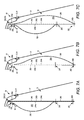
- FIGS. 7A-C are rear sectional views of the vehicle taken along the line A-A in FIG. 3 showing the curtain airbag assembly during deployment of the curtain airbag according to a second example construction.
- FIG. 8 is a flow diagram showing operations for deploying the curtain airbag with the second example construction.
- the curtain airbags employed along the sides of vehicles may be utilized to provide coverage over a vehicle's side window opening.
- the vehicle according to the description that follows includes a single side curtain airbag that can be employed to provide multiple different coverage areas over the vehicle's side window opening. In an exemplary application, for instance, the multiple different coverage areas accommodate different events.
- the side curtain airbag according to the following examples includes a shared panel. Multiple overlying auxiliary panels are connected to the shared panel to define respective inflatable chambers configured for inflation to at least partially provide respective coverage areas.
- FIGS. 1-3 show a vehicle 10 having a restraint system that includes a side curtain airbag assembly 100 having a curtain airbag 200 .
- the vehicle 10 may include a body structure 12 that is at least partially open to define one or more window openings 13 .
- the body structure 12 may include a front door 14 and a rear door 16 , each of which define a respective window opening 13 and accommodates a window 17 .
- the front door 14 and the rear door 16 can be separated from one another by an interior structural pillar or B-pillar 18 of the vehicle body structure 12 .
- a front structural pillar or A-pillar 20 of the vehicle body structure 12 is disposed forward of the front door 14 .
- a rear structural pillar or C-pillar 22 of the vehicle body structure 12 is disposed rearward of the rear door 16 .
- the A-pillar 20 , the B-pillar 18 , and the C-pillar 22 can each be covered by trim panels.
- Front seats 24 are positioned adjacent to the front door 14
- rear seats 26 are positioned adjacent to the rear door 16 .
- the side curtain airbag assembly 100 could be used with other vehicles, such as vehicles that do not include a rear door 16 but include rear seats 26 , or vehicles that lack both a rear door 16 and rear seats 26 .
- window opening 13 can refer generally to the combination of the window openings 13 defined by the front door 14 and the rear door 16 .
- window opening 13 could refer generally to an individual window opening 13 or to different combinations of window openings 13 , including those not defined by the front door 14 or the rear door 16 .
- the side curtain airbag assembly 100 prior to deployment, the side curtain airbag assembly 100 is disposed in a pre-deployment position.
- the curtain airbag 200 of the side curtain airbag assembly 100 can be hidden from view within the interior of the vehicle 10 .
- the curtain airbag 200 can be folded, rolled, or otherwise compressed into a compact state when the side curtain airbag assembly 100 is disposed in its pre-deployment position.
- the curtain airbag 200 and other components of the side curtain airbag assembly 100 are disposed at least partially behind a headliner 28 of the vehicle 10 , with the curtain airbag 200 extending underneath the headliner 28 along the longitudinal direction of the vehicle 10 , just above the front door 14 and the rear door 16 as well as the B-pillar 18 .
- the curtain airbag 200 is inflated.
- the curtain airbag 200 includes multiple internal inflatable chambers, as described below, which are individually inflated by the selective rapid introduction of inflation gas.
- the inflation causes the headliner 28 to be displaced, such as by bending the headliner 28 , thereby exposing the curtain airbag 200 to the passenger compartment of the vehicle 10 .
- the inflation further causes the curtain airbag 200 to enter the passenger compartment of the vehicle 10 .
- the curtain airbag 200 can provide multiple coverage areas over the window opening 13 .
- the multiple coverage areas can be configured to accommodate respective different events for the vehicle 10 .
- the multiple coverage areas can be fully or partially contiguous to one another, separate from one another or overlapping, depending, for instance, upon the purpose of providing the coverage areas.
- the curtain airbag 200 is configured to provide a first coverage area CA 1 and a second coverage area CA 2 over the window opening 13 .
- the first coverage area CA 1 is generally different from the second coverage area CA 2 . That is, the first coverage area CA 1 provides different coverage over the window opening 13 than the second coverage area CA 2 .
- the first coverage area CA 1 generally extends in the longitudinal direction of the vehicle 10 along and optionally above the upper portions of the window opening 13 , and particularly includes portions providing coverage over the portions of the window opening 13 adjacent the front seat 24 and the rear seat 26 .
- the second coverage area CA 2 generally extends in the longitudinal direction of the vehicle 10 and spans the height of the window opening 13 to provide coverage over the entirety of the window opening 13 , and optionally above the upper portions of the window opening 13 and below the lower portions of the window opening 13 . Accordingly, in this example, the second coverage area CA 2 overlaps the first coverage area CA 1 , as generally shown.
- the curtain airbag 200 can be constructed to define multiple internal inflatable chambers that individually, or in collaboration, at least partially provide the first coverage area CA 1 and the second coverage area CA 2 upon inflation and the ensuing entry of the curtain airbag 200 into the passenger compartment of the vehicle 10 .
- the curtain airbag 200 is constructed to include a first inflatable chamber 202 configured for inflation to at least partially provide the first coverage area CA 1 , and a second inflatable chamber 204 configured for inflation to at least partially provide the second coverage area CA 2 .
- the first inflatable chamber 202 defines an inflation aperture 206
- the second inflatable chamber 204 defines an inflation aperture 208 .
- the side curtain airbag assembly 100 includes a system 300 for deploying the curtain airbag 200 .
- the system 300 for deploying the curtain airbag 200 is generally configured to sense environmental conditions for the vehicle 10 , identify one, some or all of the events for the vehicle 10 for which the first coverage area CA 1 and the second coverage area CA 2 are configured to accommodate based on the sensed environmental conditions, and in response to the identified events, selectively inflate the first inflatable chamber 202 and/or the second inflatable chamber 204 .
- the system 300 for deploying the curtain airbag 200 includes a first inflator 210 fluidly coupled to the first inflatable chamber 202 through the inflation aperture 206 , and a second inflator 212 fluidly coupled to the second inflatable chamber 204 through the inflation aperture 208 .
- the first inflator 210 and the second inflator 212 are configured to rapidly produce inflation gas for provision to the first inflatable chamber 202 and the second inflatable chamber 204 , respectively, during inflation.
- the first inflator 210 can be selectively actuated separately from the second inflator 212 , and vice versa, so that the first inflatable chamber 202 and the second inflatable chamber 204 are separately inflatable.
- the system 300 for deploying the curtain airbag 200 further includes an airbag control unit (ACU) 220 .
- the ACU 220 is communicatively coupled with one or more event sensors 230 that provide the ACU 220 with information concerning the environmental conditions for the vehicle 10 .
- the ACU 220 is further communicatively coupled with the first inflator 210 and the second inflator 212 to allow the ACU 220 to selectively actuate the first inflator 210 and the second inflator 212 .
- the ACU 220 may be one or multiple computers including a random access memory (RAM), a read-only memory (ROM) and a central processing unit (CPU) in addition to various input and output connections.
- RAM random access memory
- ROM read-only memory
- CPU central processing unit
- the control functions of the ACU 220 described herein can be implemented by one or more software programs stored in internal or external memory and are performed by execution by the CPU. However, some or all of the functions could also be implemented by hardware components.
- the ACU 220 can be implemented as a dedicated controller for controlling the side curtain airbag assembly 100 , and optionally other airbag assemblies, or, the ACU 220 can be embodied in other controllers of the vehicle 10 .
- the ACU 220 is configured to identify one, some or all of the events for the vehicle for which the first coverage area CA 1 and the second coverage area CA 2 are configured to accommodate based on the environmental conditions for the vehicle 10 sensed by the one or more event sensors 230 .
- the one or more event sensors 230 may be or include pressure sensors configured to sense the application of pressure to the exterior of the vehicle 10 .
- the pressure sensors can be located in areas of the vehicle body structure 12 such as the front door 14 and the rear door 16 , for instance, or in other portions of the vehicle body structure 12 such as the A-pillar 20 , the B-pillar 18 or the C-pillar 22 .
- the one or more event sensors 230 may be or include accelerometers or other sensors configured to sense transverse acceleration of the vehicle 10 . Additionally, or alternatively, the one or more event sensors 230 may be or include a gyro sensor or other sensor configured to sense rotation of the vehicle 10 about its longitudinal axis.
- FIGS. 5A , 5 B and 7 A-C are rear sectional views showing the interior of the vehicle 10 during deployment of the curtain airbag 200 .
- FIGS. 5A , 5 B and FIGS. 7A-C respectively, show two example constructions for the curtain airbag 200 .
- the curtain airbag 200 defines the first inflatable chamber 202 and the second inflatable chamber 204 , and includes a shared panel 240 common to both the first inflatable chamber 202 and the second inflatable chamber 204 .
- two respective overlying auxiliary panels are connected to the shared panel 240 to define, with the shared panel 240 , the first inflatable chamber 202 and the second inflatable chamber 204 .
- the example constructions are generally described with reference to the above described example of the curtain airbag 200 that defines the first inflatable chamber 202 configured for inflation to at least partially provide the first coverage area CA 1 and the second inflatable chamber 204 configured for inflation to at least partially provide the second coverage area CA 2 .
- additional overlying auxiliary panels can be connected to the shared panel 240 to define, with the shared panel 240 , respective alternative or additional inflatable chambers configured for inflation to at least partially provide other coverage areas.
- the shared panel 240 can be sized, shaped and otherwise configured according to the desired coverage areas to be provided by the curtain airbag 200 upon the entry of the curtain airbag 200 into the passenger compartment of the vehicle 10 .
- the shared panel 240 is sized and shaped to continuously extend in the longitudinal direction of the vehicle 10 and span the height of the window opening 13 , in order to support the provision of the second coverage area CA 2 .
- the shared panel 240 could have other sizes, shapes and configurations in accordance with other coverage areas, including configurations in which the shared panel 240 does not extend continuously.
- the shared panel 240 has an upper periphery 242 a that extends in the longitudinal direction of the vehicle 10 above the upper portions of the window opening 13 , an opposing lower periphery 242 b that extends in the longitudinal direction of the vehicle 10 below the lower portions of the window opening 13 and a central portion 242 c between the upper periphery 240 a and the lower periphery 240 b .
- the shared panel 240 is attached to the vehicle 10 at its upper periphery 242 a with an attachment 246 .
- the attachment 246 can be implemented with a fastener as generally shown with other types of attachments.
- the shared panel 240 further has an inner side 244 a facing the interior of the vehicle 10 and an opposing outer side 244 b facing toward the window opening 13 .
- a first auxiliary panel 250 overlays the inner side 244 a of the shared panel 240 and is connected to the shared panel 240 to define, with the shared panel 240 , the first inflatable chamber 202 . As shown, the first inflatable chamber 202 is oriented toward the interior of the vehicle 10 .
- the first inflatable chamber 202 is configured for inflation to generally individually provide the first coverage area CA 1 over the window opening 13 .
- the first coverage area CA 1 is provided over the window opening 13 regardless of whether the second inflatable chamber 204 is inflated.
- the first auxiliary panel 250 can be connected to the shared panel 240 along its upper periphery 242 a by a seam 252 and along its central portion 242 c by a seam 254 .
- the seam 252 can be implemented with sewing, stitching, an adhesive, hook and loop type fasteners, staples, grommets and/or rivets, for instance, either alone or in combination with the attachment 246 .
- the seam 254 can similarly be implemented with sewing, stitching, an adhesive, hook and loop type fasteners, staples, grommets and/or rivets, for instance.
- a second auxiliary panel 260 overlays the outer side 244 b of the shared panel 240 and is connected to the shared panel 240 to define, with the shared panel 240 , the second inflatable chamber 204 . As shown, the second inflatable chamber 204 is oriented toward the window opening 13 .
- the second inflatable chamber 204 is configured for inflation to generally provide the second coverage area CA 2 over the window opening 13 in collaboration with the first inflatable chamber 202 .
- both the first inflatable chamber 202 and the second inflatable chamber 204 are inflated.
- the second auxiliary panel 260 can be connected to the shared panel 240 along its central portion 242 c by the seam 254 and along its lower periphery 242 b by a seam 262 .
- the seam 254 may be common to both the first auxiliary panel 250 and the second auxiliary panel 260 .
- first auxiliary panel 250 and the second auxiliary panel 260 could each be connected to the shared panel 240 along its central portion 242 c with separate seams.
- the seam 262 can be implemented with sewing, stitching, an adhesive, hook and loop type fasteners, staples, grommets and/or rivets, for instance.
- Example operations of a process 310 for implementation by the system 300 for deploying the curtain airbag 200 according to the example construction shown in FIGS. 5A and 5B are shown in FIG. 6 .
- the first inflator 210 is actuated in operation 316 to inflate the first inflatable chamber 202 and provide the first coverage area CA 1 over the window opening 13 upon the ensuing entry of the curtain airbag 200 into the passenger compartment of the vehicle 10 , as shown in FIG. 5A .
- both the first inflator 210 and the second inflator 212 are actuated in operation 318 to inflate both the first inflatable chamber 204 and the second inflatable chamber 204 , with the first inflatable chamber 202 and the second inflatable chamber 204 in conjunction providing the second coverage area CA 2 over the window opening 13 upon the ensuing entry of the curtain airbag 200 into the passenger compartment of the vehicle 10 , as shown in FIG. 5B .
- the example construction for the curtain airbag 200 shown in FIGS. 7A-C is similar to the example construction for the curtain airbag 200 shown in FIGS. 5A and 5B , except that the second inflatable chamber 204 is configured for inflation to generally individually define the second coverage area CA 2 over the window opening 13 .
- the second inflatable chamber 204 can solely define the second coverage area CA 2 over the window opening 13 regardless of whether the first inflatable chamber 202 is inflated.
- the second auxiliary panel 260 can be connected to the shared panel 240 along its upper periphery 242 a by the seam 252 and along its lower periphery 242 b by the seam 262 .
- Example operations of a process 350 for implementation by the system 300 for deploying the curtain airbag 200 according to the example construction shown in FIGS. 7A-C are shown in FIG. 8 .
- the first inflator 210 is actuated in operation 356 to inflate the first inflatable chamber 202 and provide the first coverage area CA 1 over the window opening 13 upon the ensuing entry of the curtain airbag 200 into the passenger compartment of the vehicle 10 , as shown in FIG. 7A .
- the second inflator 212 is actuated in operation 358 to inflate the second inflatable chamber 204 and provide the second coverage area CA 2 over the window opening 13 upon the ensuing entry of the curtain airbag 200 into the passenger compartment of the vehicle 10 , as shown in FIG. 7B .
- first inflator 210 is actuated in operation 356 to inflate the first inflatable chamber 202 and the second inflator 212 is actuated in operation 358 to inflate the second inflatable chamber 204 , as shown in FIG. 7C .
- the material properties of the shared panel 240 , the first auxiliary panel 250 and the second auxiliary panel 260 of the curtain airbag 200 can be configured in support of the purposes of providing the respective first coverage area CA 1 and second coverage area CA 2 over the window opening 13 .
- the first auxiliary panel 250 can have a permeability to inflation gas that allows the first inflatable chamber 202 to maintain a surface tension conducive to providing among other things energy dissipation capacity along the window opening 13 of the vehicle 10 once inflated (e.g., during an impact event involving laterally directed forces).
- the second auxiliary panel 260 can have a relatively lower permeability to inflation gas that allows the second inflatable chamber 204 to maintain a higher surface tension conducive to providing among other things a countermeasure in an ejection mitigation system for the vehicle 10 .
- the shared panel 240 can be substantially impermeable to inflation gas to fluidly isolate the first inflatable chamber 202 from the second inflatable chamber 204 .
Landscapes
- Engineering & Computer Science (AREA)
- Mechanical Engineering (AREA)
- Air Bags (AREA)
Abstract
Description
Claims (18)
Priority Applications (1)
| Application Number | Priority Date | Filing Date | Title |
|---|---|---|---|
| US14/319,278 US9150187B1 (en) | 2014-06-30 | 2014-06-30 | Curtain airbag assembly |
Applications Claiming Priority (1)
| Application Number | Priority Date | Filing Date | Title |
|---|---|---|---|
| US14/319,278 US9150187B1 (en) | 2014-06-30 | 2014-06-30 | Curtain airbag assembly |
Publications (1)
| Publication Number | Publication Date |
|---|---|
| US9150187B1 true US9150187B1 (en) | 2015-10-06 |
Family
ID=54203667
Family Applications (1)
| Application Number | Title | Priority Date | Filing Date |
|---|---|---|---|
| US14/319,278 Active US9150187B1 (en) | 2014-06-30 | 2014-06-30 | Curtain airbag assembly |
Country Status (1)
| Country | Link |
|---|---|
| US (1) | US9150187B1 (en) |
Cited By (4)
| Publication number | Priority date | Publication date | Assignee | Title |
|---|---|---|---|---|
| CN107776532A (en) * | 2016-08-24 | 2018-03-09 | 福特全球技术公司 | Airbag constraint system |
| US20180281736A1 (en) * | 2017-03-31 | 2018-10-04 | Subaru Corporation | Curtain airbag |
| US20180290617A1 (en) * | 2015-06-05 | 2018-10-11 | Autoliv Development Ab | Curtain airbag device |
| US20220314920A1 (en) * | 2021-04-02 | 2022-10-06 | Ford Global Technologies, Llc | Roof mounted airbag for protection of front row mid and outboard passengers in frontal, offset, and oblique crash modes |
Citations (26)
| Publication number | Priority date | Publication date | Assignee | Title |
|---|---|---|---|---|
| US3843150A (en) | 1970-11-24 | 1974-10-22 | Asahi Chemical Ind | Rapidly inflatable impact cushioning device for high-speed travelling vehicle |
| US5730464A (en) * | 1995-08-11 | 1998-03-24 | General Motors Corporation | Air bag module with tether |
| US6042141A (en) * | 1997-08-26 | 2000-03-28 | General Motors Corporation | Side restraint assembly |
| US6152481A (en) * | 1998-08-03 | 2000-11-28 | Delphi Technologies, Inc. | Side restraint assembly |
| US6293581B1 (en) * | 1999-04-15 | 2001-09-25 | Honda Giken Kogyo Kabushiki Kaisha | Occupant restraint device |
| US6296276B1 (en) * | 1999-09-01 | 2001-10-02 | Trw Occupant Restraint Systems Gmbh & Co. Kg | Gas bag |
| US6851706B2 (en) * | 2002-03-21 | 2005-02-08 | Autoliv Asp, Inc. | Side-impact, variable thickness vehicular airbag |
| US6854763B2 (en) | 2002-06-06 | 2005-02-15 | Autoliv Asp, Inc. | Biaxial flow inflator with independently adjusted gas orifices |
| US7192051B2 (en) | 2002-04-12 | 2007-03-20 | Toyota Jidosha Kabushiki Kaisha | Inflator |
| US7264269B2 (en) | 2002-12-18 | 2007-09-04 | Takata Corporation | Head-protecting airbag and head-protecting airbag device |
| US7316415B2 (en) * | 2004-08-30 | 2008-01-08 | Autoliv Asp, Inc. | Dual chamber airbag |
| US7350804B2 (en) * | 2004-11-08 | 2008-04-01 | Trw Vehicle Safety Systems Inc. | Inflatable vehicle occupant protection device with thorax protection |
| US7360790B2 (en) | 2002-05-22 | 2008-04-22 | Takata Corporation | Airbag with tie panel |
| US7396043B2 (en) | 2005-03-02 | 2008-07-08 | Autoliv Asp, Inc. | Multiple chambered airbag system |
| US7611164B2 (en) * | 2006-01-13 | 2009-11-03 | Honda Motor Co., Ltd. | Airbag apparatus |
| US7661702B2 (en) * | 2005-12-28 | 2010-02-16 | Honda Motor Co., Ltd. | Vehicular airbag apparatus |
| US7828322B2 (en) * | 2004-03-17 | 2010-11-09 | Takata-Petri (Ulm) Gmbh | Airbag device |
| US7954844B2 (en) * | 2008-02-21 | 2011-06-07 | Nihon Plast Co., Ltd. | Curtain air bag device and method of producing the same |
| US7988187B2 (en) * | 2008-08-07 | 2011-08-02 | Toyoda Gosei Co., Ltd | Head-protecting airbag apparatus |
| US8020888B2 (en) | 2009-10-05 | 2011-09-20 | Autoliv Asp, Inc. | Vehicle curtain airbag |
| US8414021B2 (en) | 2010-08-05 | 2013-04-09 | Toyoda Gosei Co., Ltd. | Head-protecting airbag apparatus |
| US8746734B1 (en) * | 2013-02-19 | 2014-06-10 | Autoliv Asp, Inc. | Curtain airbags with isolated chambers and construction methods |
| US8876153B2 (en) * | 2013-02-27 | 2014-11-04 | Nissan North America, Inc. | Airbag assembly |
| US8882139B2 (en) * | 2013-02-28 | 2014-11-11 | Toyoda Gosei Co., Ltd. | Head protection airbag apparatus |
| US8967660B2 (en) * | 2012-08-10 | 2015-03-03 | Toyota Jidosha Kabushiki Kaisha | Vehicle curtain airbag device |
| US20150097359A1 (en) * | 2013-10-08 | 2015-04-09 | Autoliv Asp, Inc. | 3-layer "c" shaped side airbag |
-
2014
- 2014-06-30 US US14/319,278 patent/US9150187B1/en active Active
Patent Citations (26)
| Publication number | Priority date | Publication date | Assignee | Title |
|---|---|---|---|---|
| US3843150A (en) | 1970-11-24 | 1974-10-22 | Asahi Chemical Ind | Rapidly inflatable impact cushioning device for high-speed travelling vehicle |
| US5730464A (en) * | 1995-08-11 | 1998-03-24 | General Motors Corporation | Air bag module with tether |
| US6042141A (en) * | 1997-08-26 | 2000-03-28 | General Motors Corporation | Side restraint assembly |
| US6152481A (en) * | 1998-08-03 | 2000-11-28 | Delphi Technologies, Inc. | Side restraint assembly |
| US6293581B1 (en) * | 1999-04-15 | 2001-09-25 | Honda Giken Kogyo Kabushiki Kaisha | Occupant restraint device |
| US6296276B1 (en) * | 1999-09-01 | 2001-10-02 | Trw Occupant Restraint Systems Gmbh & Co. Kg | Gas bag |
| US6851706B2 (en) * | 2002-03-21 | 2005-02-08 | Autoliv Asp, Inc. | Side-impact, variable thickness vehicular airbag |
| US7192051B2 (en) | 2002-04-12 | 2007-03-20 | Toyota Jidosha Kabushiki Kaisha | Inflator |
| US7360790B2 (en) | 2002-05-22 | 2008-04-22 | Takata Corporation | Airbag with tie panel |
| US6854763B2 (en) | 2002-06-06 | 2005-02-15 | Autoliv Asp, Inc. | Biaxial flow inflator with independently adjusted gas orifices |
| US7264269B2 (en) | 2002-12-18 | 2007-09-04 | Takata Corporation | Head-protecting airbag and head-protecting airbag device |
| US7828322B2 (en) * | 2004-03-17 | 2010-11-09 | Takata-Petri (Ulm) Gmbh | Airbag device |
| US7316415B2 (en) * | 2004-08-30 | 2008-01-08 | Autoliv Asp, Inc. | Dual chamber airbag |
| US7350804B2 (en) * | 2004-11-08 | 2008-04-01 | Trw Vehicle Safety Systems Inc. | Inflatable vehicle occupant protection device with thorax protection |
| US7396043B2 (en) | 2005-03-02 | 2008-07-08 | Autoliv Asp, Inc. | Multiple chambered airbag system |
| US7661702B2 (en) * | 2005-12-28 | 2010-02-16 | Honda Motor Co., Ltd. | Vehicular airbag apparatus |
| US7611164B2 (en) * | 2006-01-13 | 2009-11-03 | Honda Motor Co., Ltd. | Airbag apparatus |
| US7954844B2 (en) * | 2008-02-21 | 2011-06-07 | Nihon Plast Co., Ltd. | Curtain air bag device and method of producing the same |
| US7988187B2 (en) * | 2008-08-07 | 2011-08-02 | Toyoda Gosei Co., Ltd | Head-protecting airbag apparatus |
| US8020888B2 (en) | 2009-10-05 | 2011-09-20 | Autoliv Asp, Inc. | Vehicle curtain airbag |
| US8414021B2 (en) | 2010-08-05 | 2013-04-09 | Toyoda Gosei Co., Ltd. | Head-protecting airbag apparatus |
| US8967660B2 (en) * | 2012-08-10 | 2015-03-03 | Toyota Jidosha Kabushiki Kaisha | Vehicle curtain airbag device |
| US8746734B1 (en) * | 2013-02-19 | 2014-06-10 | Autoliv Asp, Inc. | Curtain airbags with isolated chambers and construction methods |
| US8876153B2 (en) * | 2013-02-27 | 2014-11-04 | Nissan North America, Inc. | Airbag assembly |
| US8882139B2 (en) * | 2013-02-28 | 2014-11-11 | Toyoda Gosei Co., Ltd. | Head protection airbag apparatus |
| US20150097359A1 (en) * | 2013-10-08 | 2015-04-09 | Autoliv Asp, Inc. | 3-layer "c" shaped side airbag |
Cited By (11)
| Publication number | Priority date | Publication date | Assignee | Title |
|---|---|---|---|---|
| US20180290617A1 (en) * | 2015-06-05 | 2018-10-11 | Autoliv Development Ab | Curtain airbag device |
| US10654438B2 (en) * | 2015-06-05 | 2020-05-19 | Autoliv Development Ab | Curtain airbag device |
| CN107776532A (en) * | 2016-08-24 | 2018-03-09 | 福特全球技术公司 | Airbag constraint system |
| US9969346B2 (en) * | 2016-08-24 | 2018-05-15 | Ford Global Technologies, Llc | Airbag restraint system |
| CN107776532B (en) * | 2016-08-24 | 2022-09-06 | 福特全球技术公司 | Airbag restraint system |
| US20180281736A1 (en) * | 2017-03-31 | 2018-10-04 | Subaru Corporation | Curtain airbag |
| CN108688609A (en) * | 2017-03-31 | 2018-10-23 | 株式会社斯巴鲁 | Curtain air bag |
| US10807555B2 (en) * | 2017-03-31 | 2020-10-20 | Subaru Corporation | Curtain airbag |
| US20220314920A1 (en) * | 2021-04-02 | 2022-10-06 | Ford Global Technologies, Llc | Roof mounted airbag for protection of front row mid and outboard passengers in frontal, offset, and oblique crash modes |
| US11498508B2 (en) * | 2021-04-02 | 2022-11-15 | Ford Global Technolgoies, Llc | Roof mounted airbag for protection of front row mid and outboard passengers in frontal, offset, and oblique crash modes |
| US11794683B2 (en) | 2021-04-02 | 2023-10-24 | Ford Global Technologies, Llc | Roof mounted airbag for protection of front row mid and outboard passengers in frontal, offset, and oblique crash modes |
Similar Documents
| Publication | Publication Date | Title |
|---|---|---|
| US10300880B2 (en) | Vehicle airbag systems and methods with magnetic elements | |
| US8876153B2 (en) | Airbag assembly | |
| US9139153B2 (en) | Vehicle side impact airbag with laterally extending thoracic chamber | |
| US9771046B2 (en) | Curtain airbag apparatus | |
| US8764053B1 (en) | Airbag assembly | |
| US7997615B2 (en) | Occupant restraint system | |
| US8740247B1 (en) | Airbag assembly | |
| US9016717B1 (en) | Curtain airbag for vertical and angular motion of occupant in rollover | |
| JP5036401B2 (en) | Curtain side airbag device | |
| JP5387609B2 (en) | Curtain airbag device | |
| JP6992549B2 (en) | Front pillar structure | |
| US9550470B2 (en) | Curtain airbag apparatus | |
| KR102165140B1 (en) | Side airbag device | |
| US9150187B1 (en) | Curtain airbag assembly | |
| US6152482A (en) | Vehicle inflatable restraint system trim with trim deploying module | |
| US6729645B2 (en) | Automobile head protection device for vehicle occupant | |
| WO2009144971A1 (en) | Head-restraining airbag system | |
| US20160082917A1 (en) | Magnetic retention assembly for a curtain airbag | |
| EP1953046B1 (en) | Vehicle occupant restraint system | |
| US11529924B2 (en) | Occupant crash protection device for vehicle | |
| US7819422B2 (en) | Vehicle occupant restraint apparatus | |
| US11305721B2 (en) | Curtain airbag system of vehicle | |
| KR102366814B1 (en) | Curtain air bag and deployment method of curtain air bag | |
| US12157429B1 (en) | Airbag cushion including a pusher chamber | |
| US11472366B2 (en) | Head protection airbag device |
Legal Events
| Date | Code | Title | Description |
|---|---|---|---|
| AS | Assignment |
Owner name: NISSAN NORTH AMERICA, INC., TENNESSEE Free format text: ASSIGNMENT OF ASSIGNORS INTEREST;ASSIGNORS:SCHIFTAN, ARI;VERNER, SARAH;REEL/FRAME:033306/0173 Effective date: 20140710 |
|
| STCF | Information on status: patent grant |
Free format text: PATENTED CASE |
|
| AS | Assignment |
Owner name: NISSAN MOTOR CO., LTD., JAPAN Free format text: ASSIGNMENT OF ASSIGNORS INTEREST;ASSIGNOR:NISSAN NORTH AMERICA, INC.;REEL/FRAME:037943/0452 Effective date: 20160308 |
|
| MAFP | Maintenance fee payment |
Free format text: PAYMENT OF MAINTENANCE FEE, 4TH YEAR, LARGE ENTITY (ORIGINAL EVENT CODE: M1551); ENTITY STATUS OF PATENT OWNER: LARGE ENTITY Year of fee payment: 4 |
|
| MAFP | Maintenance fee payment |
Free format text: PAYMENT OF MAINTENANCE FEE, 8TH YEAR, LARGE ENTITY (ORIGINAL EVENT CODE: M1552); ENTITY STATUS OF PATENT OWNER: LARGE ENTITY Year of fee payment: 8 |