US9140731B2 - Algorithm and implementation system for measuring impedance in the D-Q domain - Google Patents
Algorithm and implementation system for measuring impedance in the D-Q domain Download PDFInfo
- Publication number
- US9140731B2 US9140731B2 US13/618,513 US201213618513A US9140731B2 US 9140731 B2 US9140731 B2 US 9140731B2 US 201213618513 A US201213618513 A US 201213618513A US 9140731 B2 US9140731 B2 US 9140731B2
- Authority
- US
- United States
- Prior art keywords
- phase
- perturbations
- recited
- voltage
- electrical power
- Prior art date
- Legal status (The legal status is an assumption and is not a legal conclusion. Google has not performed a legal analysis and makes no representation as to the accuracy of the status listed.)
- Active, expires
Links
Images


Classifications
-
- G—PHYSICS
- G01—MEASURING; TESTING
- G01R—MEASURING ELECTRIC VARIABLES; MEASURING MAGNETIC VARIABLES
- G01R27/00—Arrangements for measuring resistance, reactance, impedance, or electric characteristics derived therefrom
- G01R27/02—Measuring real or complex resistance, reactance, impedance, or other two-pole characteristics derived therefrom, e.g. time constant
- G01R27/16—Measuring impedance of element or network through which a current is passing from another source, e.g. cable, power line
-
- H—ELECTRICITY
- H02—GENERATION; CONVERSION OR DISTRIBUTION OF ELECTRIC POWER
- H02J—ELECTRIC POWER NETWORKS; CIRCUIT ARRANGEMENTS OR SYSTEMS FOR SUPPLYING OR DISTRIBUTING ELECTRIC POWER; SYSTEMS FOR STORING ELECTRIC ENERGY
- H02J3/00—Circuit arrangements for AC mains or AC distribution networks
- H02J3/38—Arrangements for feeding a single network from two or more generators or sources in parallel; Arrangements for feeding already energised networks from additional generators or sources in parallel
-
- G—PHYSICS
- G01—MEASURING; TESTING
- G01R—MEASURING ELECTRIC VARIABLES; MEASURING MAGNETIC VARIABLES
- G01R27/00—Arrangements for measuring resistance, reactance, impedance, or electric characteristics derived therefrom
- G01R27/02—Measuring real or complex resistance, reactance, impedance, or other two-pole characteristics derived therefrom, e.g. time constant
- G01R27/14—Measuring resistance by measuring current or voltage obtained from a reference source
Definitions
- the present invention generally relates to a methodology and apparatus for direct measurement of impedance of an AC power source and power converter and, more particularly, to measurement of impedance of portions of a power circuit at interfaces therebetween and which may be time-varying and/or non-linear; which measurements may be conducted on-line while the power circuit is delivering power to a load.
- Power converters are, by their nature, non-linear and their dynamic behaviors are coupled with those of the load from which they receive power or the source providing power through them. As a consequence, many power electronics systems will require control in order to provide a regulated output. However, provision of such regulation causes additional phenomena that have not been previously observed or considered to be of importance, including but not limited to issues of stability.
- a power converter under regulated output control exhibits negative incremental impedance characteristics at its input. That is, in the case of converters regulating voltage (to a different form of that of the source), the current consumed by them is inversely proportional to voltage variations of the source in order to maintain a constant power flow to the load. This is the inverse behavior of resistive loads, whose current consumption is directly proportional to voltage variations of the source. Consequently, the small-signal response at a given operating point, corresponding to the linearization of the converter at such point, presents negative phase. As is well recognized in the art, negative impedance can result in instabilities and possibly oscillatory behavior of the circuit with detrimental effects to the system where they operate.
- an apparatus for measuring impedances of respective phases of a multi-phase electrical power system at any system interface between stages of the multi-phase electrical power system comprising a phase locked loop for aligning a frame of reference with an input power vector and a plurality of angles, a sweep generator for applying perturbations to respective phase of the interface over a range of frequency, in sequence, to the multi-phase electrical power system, voltage and current sensors for measuring amplitude and phase of the voltage and current responses to respective perturbations, and a computer to compute impedances of respective phases of the interface from phase and amplitude of voltage and current responses to the perturbations over the range of frequency of respective perturbations.
- FIG. 1 is a schematic illustration of on-line measurement of impedance at an exemplary interface of a three-phase power converter system
- FIG. 2 is a schematic illustration of an equivalent circuit of FIG. 1 represented in the d-q domain
- FIG. 3 is a schematic depiction of a DC power conversion system under perturbation
- FIG. 4 is a functional block diagram of an analyzer in accordance with the invention.
- FIG. 5 illustrates a suitable exemplary architecture for performing the analyzer algorithm in accordance with the invention
- FIG. 6 illustrates a preferred form of a prototype analyzer in accordance with the invention
- FIG. 7 is a schematic diagram of an exemplary and generalized system under test with the analyzer inserted
- FIG. 7A is a diagram useful for understanding measurement sweeps in accordance with the invention.
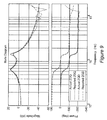
- FIG. 8 graphically illustrates experimentally measured direct-channel impedances of an exemplary test circuit
- FIG. 9 graphically illustrates experimentally measured cross-channel impedances of the same exemplary test circuit.
- FIG. 10 summarizes the development of impedance and admittance measurements from the measurements made by an embodiment of the invention.
- FIG. 1 there is shown a schematic diagram of a generalized there-phase power system having an interface between a source and a load. It should be understood that any juncture between portions of a power converter system will provide an interface between “upstream” circuits and “downstream” circuits and that the former functions as a source for the latter and the latter may be considered as a load for the former.
- current sources i Pa , i Pb and i Pc are capable of injecting current into and thus perturbing the respective phases of the power converter circuit.
- the source and load impedances e.g.
- Z sa (s) and Z la (s) for phase a) of respective phases can thus be derived from the resulting voltages and upstream and downstream currents (e.g. voltage v an , v sa and v La and currents i sa and i La for phase A).
- the multi variable stability problem of multi-phase AC power sources or loads is reduced to the scalar case and can be analyzed by the single input, single output (SISO) standard Nyquist stability theorem, as distinct from requiring use of the generalized Nyquist stability theorem or the multi-variable Nyquist stability theorem which are far more complex and burdensome and lead to excessively conservative evaluations as applied to power converters.
- SISO single input, single output
- the power system thus interfaces devices used to control power flow in order to provide power to the load, such as three-phase power converters. Analysis of these devices and systems can be performed at multiple levels, ranging from power flow and power quality all the way to models of the solid state semiconductor devices in the converters themselves. Appropriate models are chosen based on the level of analysis to be performed. Since this invention focuses on measuring impedance as a function of frequency, the models will be small signal models representing the converter and subsystem(s) behavior at a given operating point.
- a rotating coordinate system can be defined that matches the frequency of rotation of the voltage vector, making the voltage appear stationary in that frame of reference (referred to hereinafter simply as “frame”). This transformation is shown by
- the third component known as the 0-axis
- the 0-axis can be ignored. In effect, if the system is balanced, this axis is effectively zero.
- a shunt current source is placed at the point of measurement as shown in FIG. 1 .
- This system when transformed to the D-q domain may be represented as shown in FIG. 2 .
- a single port balanced time-invariant network represented in the D-q domain may be described by the following transfer function matrix:
- the perturbation is a vector and, due to the shunt configuration, that vector will split when the perturbation reaches the point of common coupling. It is assumed, however, that when a current injection is made to perturb at a different angle, that the load and source current and voltage vector perturbation will rotate by that same angular difference.
- Such a restriction gives rise to several challenges in implementing a measurement system for such a measurement subsystem.
- the first is the ability to induce a perturbation into a system.
- Such an injection must be supplied at a reasonable magnitude (e.g. 1-2% of system rated power) in order to perturb the system, and the injection equipment must be able to operate with other power sources active in the systems which are significantly larger than the injection.
- the analyzer in accordance with the invention must measure the impedance in an artificial frame of reference that does not physically exist. There are no d- and q-axis terminals to which one may connect a sensor, and such a reference frame must be derived via real time processing.
- a series voltage source or current source may be used or a series or shunt configured impedance may be used. These devices modify the system currents and voltages in order to create a perturbation. It should be noted that the location where the system is perturbed is not necessarily the same location where the resulting perturbation is measured. That is, i p2 may be used to create a perturbation while i 1 and v 1 are being measured.
- the sources shown in FIG. 3 are not in the system, but are placed there for the purpose of measuring impedances within the system via injection hardware.
- a wound-rotor induction machine can be used to inject a perturbation into the system.
- DC current is injected into the machine and the machine is allowed to synchronize with the system, after which the perturbation can be injected on top of the DC signal.
- the machine injects onto all three phases as it rotates.
- a third technique modulates a three-phase shunt-connected resistive impedance (done with a three-phase chopper circuit). This injection is made smoother with the addition of a series inductor. A power semiconductor switch shorted one resistor to create the modulation. A similar method to inject a perturbation was also created that modulated an impedance only between two of the three phases.
- a second challenge involves the presence of exogenous signals in the network during measurement. Since the network is nonlinear, it is measured during its operation. As such, there are other exogenous signals present due to the system's operation. These include, but are not limited to, line frequency harmonics, switching ripple, low frequency modulation effects, zero crossing distortions due to non-ideal behavior of diodes and diode rectifier bridges in the system, load-source interactions, and others. While attempts have been made to mitigate these effects, they still prevail in many systems.
- an alignment is chosen which defines the frame.
- either the d-axis or the q-Axis is aligned to the rotating voltage vector. If the d-q frame is aligned to a different angle, the measured impedance may also change. A property of showing no change when changing the alignment angle of the d-q frame to the rotating voltage vector is referred to as isotropism or rotational invariance.
- the impedance of a system is dependent on the alignment of the d-q frame the impedance is called anisotropic. It is therefore necessary for anisotropic systems that the d-q coordinate system is aligned properly with the variable of interest.
- it is preferred, but not required, that the d-q frame will be aligned with the d-axis such that the q-axis voltage component is centered on zero for simplicity. Such an alignment will be assumed in the following discussion.
- This alignment is usually achieved via a phase locked loop (PLL) that controls the reference frame angular velocity until it aligns with the rotating voltage vector.
- PLL phase locked loop
- the PLL will have a reaction to it, and the frame will no longer be rotating at exactly a constant frequency.
- a low pass filter on the line voltage has been attempted but will be even more significantly affected by these harmonics and other exogenous signals as the basis voltage will contain low frequency perturbation signals.
- PLL phase locked loop
- the impedances are expressed as matrices, and there exists coupling between the load and source subsystems represented by these matrices.
- a perturbation on the d-channel can cross-couple to the q-channel output, which can then interact with the load, and again cross-couple to produce a voltage response back on the d-channel.
- This interaction makes the impedance appear to include the load, and is a result of having a multi-variable system. The solution must decouple this interaction.
- D-q frame If measurements are to be taken in the D-q frame, it is necessary that a stable reference frame is established prior to measurement at the desired angle with respect to the system voltage or current and that does not vary during any measurements taken.
- phase locked loop may work for the application given that it can have a variable bandwidth which can be changed during runtime.
- a three-phase PLL is selected that decouples the positive and negative sequences of the voltage with which it is synchronizing.
- the algorithm will be implemented in software, a version of the referenced PLL, once tailored to the specific voltage sequences, can be simplified. Once the reference frame is defined via the PLL, it is possible to analyze the system dynamics in this frame by introducing perturbations into the system.
- Gain and phase analyzers have the ability to reject components of the signal which are not closely related to its own perturbation. Regardless of the technique or instrument used, the purpose of this block (also shown in FIG. 4 ) is to measure the gain from a single input to a single output.
- this is accomplished by injecting on i Pd and i Pq , and obtaining responses on i Sd (s), i Sq (s), i Ld (s), i Ld (s), v d (s), and v q (s) as described earlier.
- rotating the perturbation vector, i P so that i Pd and i Pq have a new and different proportion, there will be a second set of linearly independent responses on the vectors i s , i L and v.
- these signals are measured as three-phase variables and converted into the d-q frame in the signal processing element 41 as shown in FIG. 4 .
- the corresponding d-q terms are then sent out to the gain/phase analyzer 42 as signal A, which ultimately measures and calculates the response signals of interest, that is, transfer functions.
- the gain/phase analyzer 42 similarly generates the perturbation signal Rfout that is converted from the d-q frame into a three-phase variable by the signal processing block 41 prior to its injection into the system under test 43 through amplifiers.
- the procedure does not directly measure ratios of voltage to current perturbation responses, but instead measures voltages and currents with respect to a given repeatable reference, which remains the same for all the sweeps. Eight variables are therefore measured (four currents and four voltages) per injection, and those injections occur at two different angles.
- More than two sets of vectors may be used as well to calculate the measured impedances if multiple frequency sweeps are conducted measuring multiple responses. This requires that the multiple sweeps are performed at the exact set of frequency points so that multiple measurements exist at each of these points. This results in the construction of larger matrices as opposed to the two vectors built as described above. If n linearly independent injection vectors are used the responses can be aggregated into new matrices V(s) and I(s) as follows:
- FIG. 5 A schematic representation of functional elements and their interrelationship of this implementation of the invention is illustrated in FIG. 5 to implement the algorithm and methodology of the invention.
- the synchronization of the D-q frame with the input power for conversion of the ABC variables of FIG. 1 to the D-q domain variables shown in FIG. 2 is controlled by phase locked loop 51 while the selection and control of Frequency sweeps is performed by computer 52 .
- the perturbation signal of the logic analyzer 59 is passed through anti-aliasing filters prior to A/D conversion.
- the perturbation signal follows two channels scaled by the d-q frame gains IpdGain and IqGain to form the resultant perturbation vector in the d-q frame.
- This vector is then converted to ABC variables at 57 , and converted with D/A converter 55 into analog signals used as a reference for amplifiers 56 which are preferably coupled to the system under test through transformers.
- Current and voltage sensors 58 a and 58 b measure the responses to the perturbation sweeps and return measurements to the system through anti-aliasing filters and A/D converters for compensation of the perturbations in a manner not critical to the practice of the invention as well as gain adjustment.
- the resultant conversion of the ABC variables to the d-q domain for the two equivalent channels are performed by elements 53 a and 53 b and multiplexed through multiplexer 54 and converted into analog signals by the D/A converter 55 to provide the response signal to the impedance analyzer 59 . This operation closes the signal flow loop.
- hardware comprises a set of three amplifiers used to perform the injections and capable of producing perturbations of substantial power, sensors, transformers used to isolate the system, analog signal processing, and digital logic.
- the hardware suitable for practice of the invention may be any of a wide variety of forms, the details of which are not at all critical to the practice of the invention other than to provide current and voltage injection and measurement capabilities suitable to the power transfer capacity of the system to be tested.
- the preferred hardware architecture as described above is considered to be important.
- the preferred architecture discussed above follows algorithm and system interface requirements. It consists of injection amplifiers used to inject the perturbation into the system, coupling magnetics, current and voltage sensors for each phase, and a control system which is used to inject the disturbance.
- a prototype of the system is shown in FIG. 6 .
- the coupling of the system in accordance with the invention to an arbitrary system under test is schematically illustrated in FIG. 7 and sequentially performs the measurement sweeps as illustrated in FIG. 7A to gather the data from which the transfer functions of the phases of the ABC model of FIG. 1 can be determined.
- the invention provides a three-phase impedance analyzer for the purposes of measuring three phase impedances in the d-q frame.
- a review of existing methods indicates that while components of the total solution exist, one cohesive solution that addresses all critical issues simultaneously does not.
- the invention uses a conventional impedance analyzer and provides a suitable digital control system infrastructure built around it to enable the measurement of three-phase impedances in AC electrical systems.
- the invention achieves this function by injecting sequential perturbations on the d-q frame after proper alignment of the frame gas been achieved and measuring the response of the system in terms of the AC interface voltages and source and load currents.
Landscapes
- Physics & Mathematics (AREA)
- General Physics & Mathematics (AREA)
- Engineering & Computer Science (AREA)
- Power Engineering (AREA)
- Measurement Of Resistance Or Impedance (AREA)
Abstract
Description
making them non-stationary systems with periodic tendencies.
Due to the stationary nature of the system, it can be assumed that the transfer function between different inputs and outputs can be measured sequentially or simultaneously without any change in the results, and that measurements can be repeated as many times as necessary, retrieving the same transfer function each time. If only one side (e.g. load or source) of the system was being measured, current could simply be injected into the D-axis and the corresponding voltage components measured while keeping the Q-axis zero. As the injection must be in a shunt configuration to achieve an on-line measurement, however, this is not the case.
Accordingly, the impedances can be defined as:
From
i s(s)+i p(s)=i L(s)−Z s(s)−1 v(s)+i p(s)=Z L(s)−1 v(s) (8)
Giving:
Thus, if estimates of the values of Zs and ZL are available, an estimate can be made as to how much perturbation must be injected in order to achieve a desired voltage perturbation to be measurable beyond the quantization non-linearities introduced by the load, source, and measurement system.
v(s)=v s(s)=v L(s) (10)
[Z L(s)−1 +Z S(s)−1]−1 i P(s)=−Z S(s)i S(s)=Z L(s)i L(s) (11)
From equations (10) and (11), the current to each side can be directly calculated as:
Z S(s)−1 [Z L(s)−1 +Z S(s)−1]−1 i P(s)=i S(s)
Z L(s)−1 [Z L(s)−1 +Z S(s)−1]−1 i P(s)=i L(s) (12)2)
In this regard, it is also helpful to recognize that
i S(s)=−Z S(s)−1 Z L(s)i L(s) (13)
Thus, whenever one impedance is much greater than the other impedance, it will be difficult to measure the current response related to that side, as most of the current will flow in the opposite direction, leading to measurement range restrictions as applied to the current sensors and the associated A/D converters, which must measure the large signal response while being able to accurately measure the small signal response. Based on the estimated value of the impedances, this can be used to calculate the necessary perturbation current or voltage value in order to cause a disturbance in the system of sufficient magnitude.
Similarly, injecting a second time with a linearly independent injection vector gives a rotated response:
Notice that the impedance has not changed as the system is the same. The response has changed as dictated by the inputs and outputs. The equations containing vd1 and vd2 can be regrouped as:
From equation (16), the impedances Zldd(s) and Zldq (s) can be respectively computed as:
Similarly, this technique can be reapplied to the q-axis voltages:
Transposing and stacking these equations yields the final form:
Using these matrices as definitions, the impedance can be calculated as:
Z L(s)=[I L(s)T I L(s)]−1 I L(s)T V(s) (21)
This procedure can be repeated for the source impedance, replacing matrix IL with the corresponding matrix Is. When there are only two samples used, the approaches are identical:
[I L(s)T I L(s)]−1 I L(s)−1 I L(s)T-1 I L(s)T =I L(s)−1
Z L(s)=I L(s)T V(s) (22)
| TABLE 1 |
| System Under Test Parameters |
| Description | Value | Unit | ||
| RMS Line Current | 5 | A | ||
| Line Frequency | 500 | Hz | ||
| Load inductance | 216 | | ||
| Load capacitance | ||||
| 90 | mF | |||
| Load resistance | 3 | Ω | ||
| Source resistance | 0.3 | W | ||
To verify the impedance, the stationary frame impedance was measured via a precision impedance analyzer (HP 4194) and transformed into the D-q domain. The transformed impedance and the corresponding measurement are shown in
Claims (12)
Priority Applications (1)
| Application Number | Priority Date | Filing Date | Title |
|---|---|---|---|
| US13/618,513 US9140731B2 (en) | 2011-09-16 | 2012-09-14 | Algorithm and implementation system for measuring impedance in the D-Q domain |
Applications Claiming Priority (3)
| Application Number | Priority Date | Filing Date | Title |
|---|---|---|---|
| US201161535398P | 2011-09-16 | 2011-09-16 | |
| US13/608,218 US20130001844A1 (en) | 2010-12-08 | 2012-09-10 | Anti-vibration rubber device |
| US13/618,513 US9140731B2 (en) | 2011-09-16 | 2012-09-14 | Algorithm and implementation system for measuring impedance in the D-Q domain |
Publications (2)
| Publication Number | Publication Date |
|---|---|
| US20130099800A1 US20130099800A1 (en) | 2013-04-25 |
| US9140731B2 true US9140731B2 (en) | 2015-09-22 |
Family
ID=48135444
Family Applications (1)
| Application Number | Title | Priority Date | Filing Date |
|---|---|---|---|
| US13/618,513 Active 2033-08-31 US9140731B2 (en) | 2011-09-16 | 2012-09-14 | Algorithm and implementation system for measuring impedance in the D-Q domain |
Country Status (1)
| Country | Link |
|---|---|
| US (1) | US9140731B2 (en) |
Cited By (1)
| Publication number | Priority date | Publication date | Assignee | Title |
|---|---|---|---|---|
| US11709976B2 (en) | 2019-11-28 | 2023-07-25 | Abb Schweiz Ag | Determining Thevenin equivalent model for a converter system |
Families Citing this family (24)
| Publication number | Priority date | Publication date | Assignee | Title |
|---|---|---|---|---|
| FR2975497B1 (en) * | 2011-05-16 | 2013-06-28 | Centre Nat Rech Scient | ELECTRONIC POWER CONVERTER |
| US9562939B2 (en) * | 2012-07-30 | 2017-02-07 | Huntington Ingalls Incorporated | System and method for impedance measurement using series and shunt injection |
| US9471731B2 (en) | 2012-10-30 | 2016-10-18 | The Boeing Company | Electrical power system stability optimization system |
| US9316701B1 (en) * | 2014-05-06 | 2016-04-19 | The Florida State University Research Foundation, Inc. | Real-time small-signal stability assessment of power electronic-based components in contemporary power systems |
| CN104865480B (en) * | 2015-06-16 | 2017-09-29 | 国家电网公司 | A Method of Obtaining Nonlinear Function of Load |
| CN106329563B (en) | 2015-06-28 | 2019-05-28 | 华为技术有限公司 | Method for checking grid-connected stability of inverter and inverter |
| CN105548696B (en) * | 2015-12-16 | 2018-01-30 | 山东大学 | Blower fan harmonic wave adaptability distal end detecting system and method based on distributed constant circuit |
| US11063435B2 (en) | 2017-08-07 | 2021-07-13 | Raytheon Company | Energy-based adaptive stability control system |
| CN111417859A (en) * | 2017-12-04 | 2020-07-14 | 航天喷气发动机洛克达因股份有限公司 | Load impedance tester and measuring method |
| US11349292B2 (en) | 2019-04-09 | 2022-05-31 | Raytheon Company | Arc flash protection of power systems |
| CN110011364B (en) * | 2019-04-29 | 2023-10-13 | 华北电力大学(保定) | A control method to reduce the impact of active power load fluctuations on system stability |
| ES2867349A1 (en) * | 2019-11-28 | 2021-10-20 | Convergrid S L | SYSTEM AND PROCEDURE FOR THE INTEGRATION AND SUPERVISION OF ELECTRICAL EQUIPMENT FOR THE STABILIZATION OF ELECTRICAL NETWORKS (Machine-translation by Google Translate, not legally binding) |
| CN116235060B (en) * | 2020-07-29 | 2025-08-22 | 技术应用股份公司 | Impedance measurement of grounding systems |
| CN112003271B (en) * | 2020-08-10 | 2021-12-07 | 浙江大学 | Converter access alternating current micro-grid stability analysis method based on distributed impedance criterion |
| CN113434951B (en) * | 2021-05-26 | 2024-04-16 | 宁波吉利汽车研究开发有限公司 | A method, device and system for evaluating ripple interference resistance |
| CN113761793B (en) * | 2021-08-16 | 2024-02-27 | 固德威技术股份有限公司 | Inverter output impedance detection device and method, inverter operation control method |
| US11525881B1 (en) * | 2021-08-17 | 2022-12-13 | Fluke Corporation | Systems and methods for calibration using impedance simulation |
| CN114935692B (en) * | 2022-07-25 | 2022-11-08 | 国网浙江省电力有限公司经济技术研究院 | Method and device for measuring impedance of converter |
| CN115508619B (en) * | 2022-08-31 | 2025-04-22 | 国网河北省电力有限公司电力科学研究院 | Inverter impedance measurement method, device, terminal equipment and storage medium |
| CN116093921B (en) * | 2022-11-29 | 2025-10-31 | 西安交通大学 | Method, system, equipment and medium for modeling work frequency division mixed impedance |
| CN116184025B (en) * | 2022-12-26 | 2026-04-21 | 国网河北省电力有限公司电力科学研究院 | Impedance Measurement Methods and Systems for Power Electronic Devices |
| CN117310287B (en) * | 2023-09-27 | 2024-06-07 | 中国电力科学研究院有限公司 | Impedance decoupling measurement device and method for doubly-fed wind turbine generator-grid side |
| CN117990986B (en) * | 2024-04-02 | 2024-06-18 | 浙江大学 | A method, device, electronic equipment and medium for measuring impedance of a current transformer |
| CN118759264A (en) * | 2024-09-03 | 2024-10-11 | 浙江大学 | A method, device and medium for measuring impedance of a converter black box |
Citations (4)
| Publication number | Priority date | Publication date | Assignee | Title |
|---|---|---|---|---|
| US4851782A (en) * | 1987-01-15 | 1989-07-25 | Jeerings Donald I | High impedance fault analyzer in electric power distribution |
| US20090230980A1 (en) * | 2006-04-07 | 2009-09-17 | Michael Lamar Williams | Method for measuring d-q impedance of polyphase power grid components |
| US20120063179A1 (en) * | 2011-04-05 | 2012-03-15 | Maozhong Gong | System and method for damping lc circuits in power conversion systems |
| US20120259477A1 (en) * | 2011-04-05 | 2012-10-11 | King Fahd University Of Petroleum And Minerals | Particle swarm optimization system and method for microgrids |
-
2012
- 2012-09-14 US US13/618,513 patent/US9140731B2/en active Active
Patent Citations (4)
| Publication number | Priority date | Publication date | Assignee | Title |
|---|---|---|---|---|
| US4851782A (en) * | 1987-01-15 | 1989-07-25 | Jeerings Donald I | High impedance fault analyzer in electric power distribution |
| US20090230980A1 (en) * | 2006-04-07 | 2009-09-17 | Michael Lamar Williams | Method for measuring d-q impedance of polyphase power grid components |
| US20120063179A1 (en) * | 2011-04-05 | 2012-03-15 | Maozhong Gong | System and method for damping lc circuits in power conversion systems |
| US20120259477A1 (en) * | 2011-04-05 | 2012-10-11 | King Fahd University Of Petroleum And Minerals | Particle swarm optimization system and method for microgrids |
Cited By (1)
| Publication number | Priority date | Publication date | Assignee | Title |
|---|---|---|---|---|
| US11709976B2 (en) | 2019-11-28 | 2023-07-25 | Abb Schweiz Ag | Determining Thevenin equivalent model for a converter system |
Also Published As
| Publication number | Publication date |
|---|---|
| US20130099800A1 (en) | 2013-04-25 |
Similar Documents
| Publication | Publication Date | Title |
|---|---|---|
| US9140731B2 (en) | Algorithm and implementation system for measuring impedance in the D-Q domain | |
| Francis et al. | An algorithm and implementation system for measuring impedance in the DQ domain | |
| Roinila et al. | Hardware-in-the-loop methods for real-time frequency-response measurements of on-board power distribution systems | |
| Bojoi et al. | Enhanced power quality control strategy for single-phase inverters in distributed generation systems | |
| Riccobono et al. | Noninvasive online parametric identification of three-phase AC power impedances to assess the stability of grid-tied power electronic inverters in LV networks | |
| Huang et al. | Small-signal impedance measurement of power-electronics-based AC power systems using line-to-line current injection | |
| Etemadi et al. | A decentralized robust control strategy for multi-DER microgrids—Part II: Performance evaluation | |
| Roscoe et al. | Architecture of a network-in-the-loop environment for characterizing AC power-system behavior | |
| Filipski | A new approach to reactive current and reactive power measurement in nonsinusoidal systems | |
| Zaker et al. | Small signal equivalent model of synchronous generator-based grid-connected microgrid using improved Heffron-Phillips model | |
| CN111239491A (en) | Generalized impedance real-time experimental measurement method adopting physical controller disturbance injection | |
| CN106505840A (en) | A kind of grid-connected photovoltaic inverter harmonic wave management method | |
| Adzic et al. | PLL synchronization in grid-connected converters | |
| Shen | Online measurement of three-phase AC power system impedance in synchronous coordinates | |
| Gianesini et al. | Comparison of methods for determining harmonic distortion contributions using the IEEE benchmark test system | |
| Litrán et al. | Electromagnetic compatibility analysis of a control strategy for a hybrid active filter | |
| EP4625747A1 (en) | Determining power converter characteristic and performing stability analysis | |
| CN116776537A (en) | Impedance model construction method and system for 24-pulse uncontrolled rectifier | |
| Lundstrom et al. | Implementation and validation of advanced unintentional islanding testing using power hardware-in-the-loop (PHIL) simulation | |
| Motwani et al. | Modeling of power electronics systems and PWM modulators in harmonic-state space | |
| Quester et al. | Online impedance measurement of a modular multilevel converter | |
| Rasheduzzaman et al. | Small-signal modeling of a three-phase isolated inverter with both voltage and frequency droop control | |
| Brogan et al. | Harmonic model of the network bridge power converter for wind farm harmonic studies | |
| Poon et al. | High-speed hardware-in-the loop platform for rapid prototyping of power electronics systems | |
| Alexandra et al. | Development of a proportional+ resonant (PR) controller for a three-phase AC micro-grid system |
Legal Events
| Date | Code | Title | Description |
|---|---|---|---|
| AS | Assignment |
Owner name: VIRGINIA TECH INTELLECTUAL PROPERTIES, INC., VIRGI Free format text: ASSIGNMENT OF ASSIGNORS INTEREST;ASSIGNOR:VIRGINIA POLYTECHNIC INSTITUTE AND STATE UNIVERSITY;REEL/FRAME:031369/0798 Effective date: 20130919 Owner name: VIRGINIA POLYTECHNIC INSTITUTE AND STATE UNIVERSIT Free format text: ASSIGNMENT OF ASSIGNORS INTEREST;ASSIGNORS:FRANCIS, GERALD;BURGOS, ROLANDO;BOROYEVICH, DUSHAN;AND OTHERS;SIGNING DATES FROM 20120920 TO 20121030;REEL/FRAME:031369/0860 |
|
| FEPP | Fee payment procedure |
Free format text: PAYOR NUMBER ASSIGNED (ORIGINAL EVENT CODE: ASPN); ENTITY STATUS OF PATENT OWNER: LARGE ENTITY |
|
| AS | Assignment |
Owner name: THE BOEING COMPANY, ILLINOIS Free format text: ASSIGNMENT OF ASSIGNORS INTEREST;ASSIGNORS:KARIMI, KAMIAR;FU, SHEAU-WEI JOHNNY;REEL/FRAME:036327/0748 Effective date: 20150809 |
|
| STCF | Information on status: patent grant |
Free format text: PATENTED CASE |
|
| MAFP | Maintenance fee payment |
Free format text: PAYMENT OF MAINTENANCE FEE, 4TH YEAR, LARGE ENTITY (ORIGINAL EVENT CODE: M1551); ENTITY STATUS OF PATENT OWNER: LARGE ENTITY Year of fee payment: 4 |
|
| MAFP | Maintenance fee payment |
Free format text: PAYMENT OF MAINTENANCE FEE, 8TH YEAR, LARGE ENTITY (ORIGINAL EVENT CODE: M1552); ENTITY STATUS OF PATENT OWNER: LARGE ENTITY Year of fee payment: 8 |