US9139143B2 - Robust wires-to-meter connection - Google Patents
Robust wires-to-meter connection Download PDFInfo
- Publication number
- US9139143B2 US9139143B2 US13/910,827 US201313910827A US9139143B2 US 9139143 B2 US9139143 B2 US 9139143B2 US 201313910827 A US201313910827 A US 201313910827A US 9139143 B2 US9139143 B2 US 9139143B2
- Authority
- US
- United States
- Prior art keywords
- flexible portion
- compartment
- wires
- case
- remote end
- Prior art date
- Legal status (The legal status is an assumption and is not a legal conclusion. Google has not performed a legal analysis and makes no representation as to the accuracy of the status listed.)
- Active, expires
Links
- 239000004020 conductor Substances 0.000 claims description 23
- 238000000034 method Methods 0.000 claims description 14
- 238000005452 bending Methods 0.000 claims description 4
- 238000007789 sealing Methods 0.000 claims description 3
- 238000004513 sizing Methods 0.000 claims 1
- XLYOFNOQVPJJNP-UHFFFAOYSA-N water Substances O XLYOFNOQVPJJNP-UHFFFAOYSA-N 0.000 abstract description 3
- NMWSKOLWZZWHPL-UHFFFAOYSA-N 3-chlorobiphenyl Chemical compound ClC1=CC=CC(C=2C=CC=CC=2)=C1 NMWSKOLWZZWHPL-UHFFFAOYSA-N 0.000 description 5
- 101001082832 Saccharomyces cerevisiae (strain ATCC 204508 / S288c) Pyruvate carboxylase 2 Proteins 0.000 description 5
- 239000004593 Epoxy Substances 0.000 description 4
- 229910000679 solder Inorganic materials 0.000 description 4
- 230000001681 protective effect Effects 0.000 description 2
- 238000010420 art technique Methods 0.000 description 1
- 230000015572 biosynthetic process Effects 0.000 description 1
- 238000002788 crimping Methods 0.000 description 1
- 230000008030 elimination Effects 0.000 description 1
- 238000003379 elimination reaction Methods 0.000 description 1
- 229920002457 flexible plastic Polymers 0.000 description 1
- 238000003780 insertion Methods 0.000 description 1
- 230000037431 insertion Effects 0.000 description 1
- 238000009413 insulation Methods 0.000 description 1
- 239000000463 material Substances 0.000 description 1
- 230000013011 mating Effects 0.000 description 1
- 238000002844 melting Methods 0.000 description 1
- 230000008018 melting Effects 0.000 description 1
- 238000012986 modification Methods 0.000 description 1
- 230000004048 modification Effects 0.000 description 1
- 230000035515 penetration Effects 0.000 description 1
- 238000005476 soldering Methods 0.000 description 1
- 239000000758 substrate Substances 0.000 description 1
Images


Classifications
-
- B—PERFORMING OPERATIONS; TRANSPORTING
- B60—VEHICLES IN GENERAL
- B60R—VEHICLES, VEHICLE FITTINGS, OR VEHICLE PARTS, NOT OTHERWISE PROVIDED FOR
- B60R16/00—Electric or fluid circuits specially adapted for vehicles and not otherwise provided for; Arrangement of elements of electric or fluid circuits specially adapted for vehicles and not otherwise provided for
- B60R16/02—Electric or fluid circuits specially adapted for vehicles and not otherwise provided for; Arrangement of elements of electric or fluid circuits specially adapted for vehicles and not otherwise provided for electric constitutive elements
- B60R16/0207—Wire harnesses
- B60R16/0215—Protecting, fastening and routing means therefor
-
- H—ELECTRICITY
- H05—ELECTRIC TECHNIQUES NOT OTHERWISE PROVIDED FOR
- H05K—PRINTED CIRCUITS; CASINGS OR CONSTRUCTIONAL DETAILS OF ELECTRIC APPARATUS; MANUFACTURE OF ASSEMBLAGES OF ELECTRICAL COMPONENTS
- H05K1/00—Printed circuits
- H05K1/02—Details
- H05K1/14—Structural association of two or more printed circuits
- H05K1/147—Structural association of two or more printed circuits at least one of the printed circuits being bent or folded, e.g. by using a flexible printed circuit
-
- H—ELECTRICITY
- H05—ELECTRIC TECHNIQUES NOT OTHERWISE PROVIDED FOR
- H05K—PRINTED CIRCUITS; CASINGS OR CONSTRUCTIONAL DETAILS OF ELECTRIC APPARATUS; MANUFACTURE OF ASSEMBLAGES OF ELECTRICAL COMPONENTS
- H05K3/00—Apparatus or processes for manufacturing printed circuits
- H05K3/30—Assembling printed circuits with electric components, e.g. with resistor
- H05K3/32—Assembling printed circuits with electric components, e.g. with resistor electrically connecting electric components or wires to printed circuits
-
- Y—GENERAL TAGGING OF NEW TECHNOLOGICAL DEVELOPMENTS; GENERAL TAGGING OF CROSS-SECTIONAL TECHNOLOGIES SPANNING OVER SEVERAL SECTIONS OF THE IPC; TECHNICAL SUBJECTS COVERED BY FORMER USPC CROSS-REFERENCE ART COLLECTIONS [XRACs] AND DIGESTS
- Y10—TECHNICAL SUBJECTS COVERED BY FORMER USPC
- Y10T—TECHNICAL SUBJECTS COVERED BY FORMER US CLASSIFICATION
- Y10T29/00—Metal working
- Y10T29/49—Method of mechanical manufacture
- Y10T29/49002—Electrical device making
- Y10T29/49117—Conductor or circuit manufacturing
- Y10T29/49169—Assembling electrical component directly to terminal or elongated conductor
Definitions
- This invention relates to a meter for motorcycles or the like, and in particular to an approach to connecting the individual wires of a wire bundle to an indicator dashboard or similar meter (hereafter collectively referred to as “dashboard”) that is mounted to the motorcycle bar for displaying information (speed, temperature, etc.).
- dashboard an indicator dashboard or similar meter
- the wire bundle comprises several insulated wires that emanate from connections to detectors or sensors that are located on the vehicle away from the dashboard.
- the wires are bundled within a protective outer sheath. The end of the sheath enters the dashboard case and the individual wires are connected in some manner to the main circuit board of the dashboard.
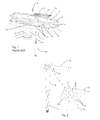
- FIG. 1 illustrates a prior art approach for connecting the individual wires of a wire bundle to an indicator dashboard.
- the case 1 of the dashboard is typically mounted in front of the motorcycle bar to enable easy viewing of the dashboard display by a rider.
- a battery 6 is secured in a mounting in the case by a cover 7 and O-ring 5 .
- the case 1 includes and interior 12 that houses the main circuit board and associated display components.
- FIG. 1 shows the bottom of the case housing 13 and a resilient seal 3 that fits between the housing and a case cover (not shown) that includes a transparent lens for viewing the display that is housed in the case.
- a wire bundle 11 is enclosed in a protective sheath 10 and enters an opening in the back of the case 1 .
- the termini of these wires 11 (hereafter sometimes referred to as “entry” wires) are connected to the underside of an interface printed circuit board (PCB) 2 .
- the ends of several, smaller “internal” wires 15 are joined to the upper surface of the interface PCB 2 .
- the internal wires 15 are bent to extend away from and generally parallel to the plane of the PCB.
- the outer ends of the internal wires 15 are crimped into a connector 14 that connects to the main circuit board (not shown) that is carried inside the case.
- the PCB 2 is seated inside of a well 16 that is defined in the interior 12 of the case 1 .
- the well 16 is a compartment that is defined by the back wall of the case and by four, inwardly projecting thin sidewalls 17 that define a cubical volume within which the PCB 2 is secured.
- the wire bundle 11 extends through the opening in the back wall of the meter case to protrude inside the well 16 , for connection to the interface PCB as noted above.
- the well 16 is filled with epoxy for the purpose of providing strain relief and preventing water from migrating into the case.
- the prior art assembly process for connecting the internal wires 15 between the upper surface of the interface PCB 2 and the main circuit board requires soldering of the ends of the wires 15 to the PCB and crimping the other ends of the wires into a connector that is in turn inserted into the mating connector carried on the main circuit board.
- the length of the wires between the PCB and connector 14 is made slightly longer than the distance between the wire ends at the PCB and the connector when finally assembled. Accordingly, each of the wires is necessarily bent slightly during and after assembly. Controlling the final configuration of the bends is difficult because each individual wire is free to buckle in any direction (upwardly, downwardly or sideways).
- the prior art device is also susceptible to failure attributable to vibration and penetration of moisture into the case.
- the solder joints of the internal wires can be stressed by the continuous vibration occurring during operation of the motorcycle, and eventually separate from the PCB 2 at the location where the wire ends are soldered to the PCB.
- One way to address this problem is to reduce the mass of the wires (hence reduce the damaging energy transmitted via vibration) by using very small diameter wires.
- the attendant higher melting points of such solders calls for relatively stiffer insulating jackets over the wire than is required with lead-based solders. The stiffer insulation in turn increases the overall mass of the wires, and thus returns the damaging vibration problem.
- the invention disclosed here provides an apparatus for conducting signals from several signal-carrying, bundled wires to a circuit member that is mounted within the interior of a sealed case, and in particular an assembly for conducting the signals while providing a robust, compact and water-resistant connection between the internal main circuit and the entry wires.
- FIG. 1 is an assembly view of components used in a prior art technique for connecting a wire bundle inside of a dashboard.
- FIG. 2 is a perspective view, with an enlarged detail showing a preferred embodiment of the connection technique of the current invention.
- FIG. 2 shows the underside of a conductor assembly component of the present invention.
- FIG. 3 is a perspective, top view of the conductor assembly component.
- FIG. 4 is a cut-away, top perspective view of a dashboard case with which the preferred connection technique of the current invention is implemented.
- FIGS. 2-4 illustrate a preferred embodiment of the present invention.
- FIG. 2 includes a perspective view and an enlarged detail showing the underside of a conductor assembly 22 component of the present invention.
- the conductor assembly 22 includes a rigid portion 24 which can be formed of conventional printed circuit board material.
- the rigid portion 24 is planar and generally square shaped. As seen in FIG. 4 , the rigid portion 24 fits inside of a cubical well 16 that is a compartment formed in the interior 12 of the case 1 .
- the well 16 is defined by four, inwardly projecting thin sidewalls 17 that define the cubical volume within which the rigid portion 24 is seated.
- the back of the dashboard case defines a protruding cylinder 30 that includes a bore or opening 32 through which the sheath 10 of the wire bundle extends.
- each wire 11 of the wire bundle terminates at the underside of the rigid portion 24 of the conductor assembly 22 ( FIG. 2 ).
- the exposed terminus of each wire 11 passes into a through-hole in the conductor assembly 22 and is soldered to a flanged, conductive sleeve 34 that lines the hole to thus electrically connect the wires 11 with conductive traces 36 ( FIG. 4 ) that are printed on the upper surface of a flexible portion 23 of the conductor assembly.
- the flexible portion 23 of the conductor assembly 22 is preferably a flexible plastic substrate having the conductive traces 36 printed thereon.
- the flexible portion 23 is, like the rigid portion 24 , planar in the sense that it is a thin, ribbon-like member having flat upper and lower surfaces. In this embodiment, the flexible portion 23 overlays and is bonded to the rigid portion 24 . At one edge of the rigid portion 24 , the flexible portion 23 extends away from the rigid portion to a remote end 38 ( FIG. 3 ) that is configured for attachment to the main circuit board of the dashboard.
- the thin, ribbon-like flexible portion 23 of the conductor assembly is a unitary element, the bending behavior of which is readily controlled (as opposed to the unpredictable, individualized buckling of the several, separate internal wires 15 as discussed above).
- the flexible portion 23 most readily bends in a direction transverse to its long axis, such as shown at bends 42 in FIG. 4 . Problematic sideways buckling or bending (as discussed above) of the flexible portion is thus quite unlikely during the assembly process.
- the combination of the relatively low mass of the flexible portion 23 (as compared to that of the prior art internal wires 15 ) and the elimination of soldered internal-wire-to-PCB connections effectively eliminates the damaging vibration problem of the prior art.
- the composition of the flexible portion is such that it holds its shape once bent. This feature thus enables the flexible portion 23 to be bent at specific locations before or during assembly (such as bends 42 in FIG. 4 ) so that once connected, the flexible portion 23 will readily assume a predicted location within the case. For instance, the controlled location of the bends 42 shown in FIG. 4 results in the formation of a predictably sized and located trough-like volume into which volume other internal components can located within the compact dashboard case 1 .
- the flexible portion 23 conforms to the shape of a sidewall 17 of the well and extends across a flat, smooth upper edge of a sidewall 17 . That is, unlike the prior art, the flat upper edge of the wall 17 over which the flexible portion 23 passes has no grooves or other irregularities that might provide gaps between the flexible portion 23 and wall 17 , which gaps could enable moisture that may enter the well to penetrate outside of the well 16 and to the main circuit board as described above with respect to the prior art.
- fasteners that extend through holes 40 provided through the conductor assembly 22 are used to anchor an end of the conductor assembly (that is, the rigid portion 24 and overlying part of the flexible portion 23 ) to the interior of the well 16 .
- a square flat cover plate (not shown) that conforms to the shape of the well 16 is then secured over the upper edges of the well sidewalls 17 to enclose the well, which is filled with epoxy to seal the well and provide strain relief to the wire junctions.
- planar flexible portion 23 thus passes between the substantially flat, opposed surfaces of the sidewall 17 and cover plate, thereby allowing the flexible portion to extend from the well without creating any gaps for enabling moisture to move out of the well in the event that the epoxy seal fails or is damaged in a manner that allows outside moisture to enter the well.
Landscapes
- Engineering & Computer Science (AREA)
- Mechanical Engineering (AREA)
- Insertion, Bundling And Securing Of Wires For Electric Apparatuses (AREA)
- Instrument Panels (AREA)
Abstract
Description
Claims (13)
Priority Applications (1)
| Application Number | Priority Date | Filing Date | Title |
|---|---|---|---|
| US13/910,827 US9139143B2 (en) | 2013-03-21 | 2013-06-05 | Robust wires-to-meter connection |
Applications Claiming Priority (2)
| Application Number | Priority Date | Filing Date | Title |
|---|---|---|---|
| US201361804162P | 2013-03-21 | 2013-03-21 | |
| US13/910,827 US9139143B2 (en) | 2013-03-21 | 2013-06-05 | Robust wires-to-meter connection |
Publications (2)
| Publication Number | Publication Date |
|---|---|
| US20140285981A1 US20140285981A1 (en) | 2014-09-25 |
| US9139143B2 true US9139143B2 (en) | 2015-09-22 |
Family
ID=51568992
Family Applications (1)
| Application Number | Title | Priority Date | Filing Date |
|---|---|---|---|
| US13/910,827 Active 2034-01-19 US9139143B2 (en) | 2013-03-21 | 2013-06-05 | Robust wires-to-meter connection |
Country Status (1)
| Country | Link |
|---|---|
| US (1) | US9139143B2 (en) |
Citations (7)
| Publication number | Priority date | Publication date | Assignee | Title |
|---|---|---|---|---|
| US5255155A (en) * | 1990-09-19 | 1993-10-19 | Sumitomo Wiring Systems, Ltd. | Structure of electric circuit panel for instrument panel of automobile and method for forming the same |
| US6512677B1 (en) * | 2001-08-06 | 2003-01-28 | Sauer-Danfoss, Inc. | Electronic connection cover for a hydraulic component housing utilizing a sealed printed circuit board |
| US20100128449A1 (en) * | 2008-05-16 | 2010-05-27 | Psion Teklogix Inc. | Ruggedized Housing and Components For A Handled Device |
| US20110242618A1 (en) * | 2010-03-30 | 2011-10-06 | Brother Kogyo Kaubushiki Kaisha | Image Reading Apparatus |
| US20130264107A1 (en) * | 2012-04-05 | 2013-10-10 | Tyco Electronics Corporation | Circuit board and wire assembly |
| US20140165726A1 (en) * | 2012-12-18 | 2014-06-19 | Trail Tech, Inc. | Speed Sensor Assembly |
| US20150195927A1 (en) * | 2014-01-07 | 2015-07-09 | Samsung Electronics Co., Ltd. | Electronic device having waterproof structure |
-
2013
- 2013-06-05 US US13/910,827 patent/US9139143B2/en active Active
Patent Citations (7)
| Publication number | Priority date | Publication date | Assignee | Title |
|---|---|---|---|---|
| US5255155A (en) * | 1990-09-19 | 1993-10-19 | Sumitomo Wiring Systems, Ltd. | Structure of electric circuit panel for instrument panel of automobile and method for forming the same |
| US6512677B1 (en) * | 2001-08-06 | 2003-01-28 | Sauer-Danfoss, Inc. | Electronic connection cover for a hydraulic component housing utilizing a sealed printed circuit board |
| US20100128449A1 (en) * | 2008-05-16 | 2010-05-27 | Psion Teklogix Inc. | Ruggedized Housing and Components For A Handled Device |
| US20110242618A1 (en) * | 2010-03-30 | 2011-10-06 | Brother Kogyo Kaubushiki Kaisha | Image Reading Apparatus |
| US20130264107A1 (en) * | 2012-04-05 | 2013-10-10 | Tyco Electronics Corporation | Circuit board and wire assembly |
| US20140165726A1 (en) * | 2012-12-18 | 2014-06-19 | Trail Tech, Inc. | Speed Sensor Assembly |
| US20150195927A1 (en) * | 2014-01-07 | 2015-07-09 | Samsung Electronics Co., Ltd. | Electronic device having waterproof structure |
Also Published As
| Publication number | Publication date |
|---|---|
| US20140285981A1 (en) | 2014-09-25 |
Similar Documents
| Publication | Publication Date | Title |
|---|---|---|
| US10012373B2 (en) | Mounting base for an electrical component having a housing with a groove with a convergent bottom for crimping an electrical wire | |
| US9270056B2 (en) | Connector | |
| CN110618514A (en) | Optical device for vehicle comprising heating element | |
| JP2006174431A (en) | Image pickup module and image pickup module assembling method | |
| US20200194951A1 (en) | Endoscope device and cable assembly thereof | |
| US9257800B2 (en) | Cable connector assembly with a shorter size and method of assembling the same | |
| JP3200755U (en) | Device for receiving cable conductors in contact | |
| CN103855521A (en) | Electrical connection structure between module device and an external device | |
| KR101873950B1 (en) | Package case of electronic device | |
| KR20080096754A (en) | Waterproof structure of connector housing | |
| JP6472897B2 (en) | Electrical connector kit, electronic component, and assembly method | |
| US8614399B2 (en) | Electric junction box | |
| TW200402911A (en) | Electronic connector for a cable | |
| CN108270109A (en) | Micro coaxial cable connector assembly and its manufacturing method | |
| JP6844455B2 (en) | Circuit equipment | |
| JP2018081959A (en) | Semiconductor module | |
| CN206250455U (en) | Connector for modular | |
| US20080160823A1 (en) | Electrical multipoint connector | |
| US9139143B2 (en) | Robust wires-to-meter connection | |
| JPWO2007004400A1 (en) | Pressure sensor and manufacturing method thereof | |
| US20150031245A1 (en) | Cable electrical connector assembly having an insulative body with a slot | |
| CN107732480B (en) | cable connector assembly | |
| JP5669076B2 (en) | Substrate fixing structure and physical quantity sensor | |
| JP2015130266A (en) | Coaxial connector device | |
| JP6713535B2 (en) | Method for manufacturing a device for detecting at least one characteristic of a flow medium in a measuring space |
Legal Events
| Date | Code | Title | Description |
|---|---|---|---|
| AS | Assignment |
Owner name: TRAIL TECH, INC, WASHINGTON Free format text: ASSIGNMENT OF ASSIGNORS INTEREST;ASSIGNORS:BORO, JONATHAN V.S.;WOTTON, GEOFFREY;REEL/FRAME:032348/0549 Effective date: 20130627 |
|
| STCF | Information on status: patent grant |
Free format text: PATENTED CASE |
|
| FEPP | Fee payment procedure |
Free format text: PAYOR NUMBER ASSIGNED (ORIGINAL EVENT CODE: ASPN); ENTITY STATUS OF PATENT OWNER: LARGE ENTITY |
|
| AS | Assignment |
Owner name: POLARIS INDUSTRIES INC., MINNESOTA Free format text: ASSIGNMENT OF ASSIGNORS INTEREST;ASSIGNOR:TRAIL TECH, INC.;REEL/FRAME:039253/0132 Effective date: 20160722 |
|
| FEPP | Fee payment procedure |
Free format text: PAT HOLDER NO LONGER CLAIMS SMALL ENTITY STATUS, ENTITY STATUS SET TO UNDISCOUNTED (ORIGINAL EVENT CODE: STOL); ENTITY STATUS OF PATENT OWNER: LARGE ENTITY |
|
| FEPP | Fee payment procedure |
Free format text: PETITION RELATED TO MAINTENANCE FEES GRANTED (ORIGINAL EVENT CODE: PTGR) |
|
| MAFP | Maintenance fee payment |
Free format text: PAYMENT OF MAINTENANCE FEE, 4TH YEAR, LARGE ENTITY (ORIGINAL EVENT CODE: M1551); ENTITY STATUS OF PATENT OWNER: LARGE ENTITY Year of fee payment: 4 |
|
| MAFP | Maintenance fee payment |
Free format text: PAYMENT OF MAINTENANCE FEE, 8TH YEAR, LARGE ENTITY (ORIGINAL EVENT CODE: M1552); ENTITY STATUS OF PATENT OWNER: LARGE ENTITY Year of fee payment: 8 |