US9132881B2 - Rubber isolation system incorporated between the compression rod and the gas spring assembly of a bicycle fork - Google Patents
Rubber isolation system incorporated between the compression rod and the gas spring assembly of a bicycle fork Download PDFInfo
- Publication number
- US9132881B2 US9132881B2 US13/481,109 US201213481109A US9132881B2 US 9132881 B2 US9132881 B2 US 9132881B2 US 201213481109 A US201213481109 A US 201213481109A US 9132881 B2 US9132881 B2 US 9132881B2
- Authority
- US
- United States
- Prior art keywords
- compression rod
- piston
- fork leg
- assembly
- adjacent
- Prior art date
- Legal status (The legal status is an assumption and is not a legal conclusion. Google has not performed a legal analysis and makes no representation as to the accuracy of the status listed.)
- Expired - Fee Related, expires
Links
Images


Classifications
-
- B—PERFORMING OPERATIONS; TRANSPORTING
- B62—LAND VEHICLES FOR TRAVELLING OTHERWISE THAN ON RAILS
- B62K—CYCLES; CYCLE FRAMES; CYCLE STEERING DEVICES; RIDER-OPERATED TERMINAL CONTROLS SPECIALLY ADAPTED FOR CYCLES; CYCLE AXLE SUSPENSIONS; CYCLE SIDE-CARS, FORECARS, OR THE LIKE
- B62K25/00—Axle suspensions
- B62K25/04—Axle suspensions for mounting axles resiliently on cycle frame or fork
- B62K25/06—Axle suspensions for mounting axles resiliently on cycle frame or fork with telescopic fork, e.g. including auxiliary rocking arms
- B62K25/08—Axle suspensions for mounting axles resiliently on cycle frame or fork with telescopic fork, e.g. including auxiliary rocking arms for front wheel
-
- F—MECHANICAL ENGINEERING; LIGHTING; HEATING; WEAPONS; BLASTING
- F16—ENGINEERING ELEMENTS AND UNITS; GENERAL MEASURES FOR PRODUCING AND MAINTAINING EFFECTIVE FUNCTIONING OF MACHINES OR INSTALLATIONS; THERMAL INSULATION IN GENERAL
- F16F—SPRINGS; SHOCK-ABSORBERS; MEANS FOR DAMPING VIBRATION
- F16F9/00—Springs, vibration-dampers, shock-absorbers, or similarly-constructed movement-dampers using a fluid or the equivalent as damping medium
- F16F9/02—Springs, vibration-dampers, shock-absorbers, or similarly-constructed movement-dampers using a fluid or the equivalent as damping medium using gas only or vacuum
- F16F9/0209—Telescopic
- F16F9/0218—Mono-tubular units
-
- F—MECHANICAL ENGINEERING; LIGHTING; HEATING; WEAPONS; BLASTING
- F16—ENGINEERING ELEMENTS AND UNITS; GENERAL MEASURES FOR PRODUCING AND MAINTAINING EFFECTIVE FUNCTIONING OF MACHINES OR INSTALLATIONS; THERMAL INSULATION IN GENERAL
- F16F—SPRINGS; SHOCK-ABSORBERS; MEANS FOR DAMPING VIBRATION
- F16F9/00—Springs, vibration-dampers, shock-absorbers, or similarly-constructed movement-dampers using a fluid or the equivalent as damping medium
- F16F9/32—Details
- F16F9/3207—Constructional features
- F16F9/3228—Constructional features of connections between pistons and piston rods
-
- F—MECHANICAL ENGINEERING; LIGHTING; HEATING; WEAPONS; BLASTING
- F16—ENGINEERING ELEMENTS AND UNITS; GENERAL MEASURES FOR PRODUCING AND MAINTAINING EFFECTIVE FUNCTIONING OF MACHINES OR INSTALLATIONS; THERMAL INSULATION IN GENERAL
- F16F—SPRINGS; SHOCK-ABSORBERS; MEANS FOR DAMPING VIBRATION
- F16F9/00—Springs, vibration-dampers, shock-absorbers, or similarly-constructed movement-dampers using a fluid or the equivalent as damping medium
- F16F9/32—Details
- F16F9/34—Special valve constructions; Shape or construction of throttling passages
- F16F9/3415—Special valve constructions; Shape or construction of throttling passages characterised by comprising plastics, elastomeric or porous elements
-
- F—MECHANICAL ENGINEERING; LIGHTING; HEATING; WEAPONS; BLASTING
- F16—ENGINEERING ELEMENTS AND UNITS; GENERAL MEASURES FOR PRODUCING AND MAINTAINING EFFECTIVE FUNCTIONING OF MACHINES OR INSTALLATIONS; THERMAL INSULATION IN GENERAL
- F16F—SPRINGS; SHOCK-ABSORBERS; MEANS FOR DAMPING VIBRATION
- F16F9/00—Springs, vibration-dampers, shock-absorbers, or similarly-constructed movement-dampers using a fluid or the equivalent as damping medium
- F16F9/32—Details
- F16F9/50—Special means providing automatic damping adjustment, i.e. self-adjustment of damping by particular sliding movements of a valve element, other than flexions or displacement of valve discs; Special means providing self-adjustment of spring characteristics
- F16F9/512—Means responsive to load action, i.e. static load on the damper or dynamic fluid pressure changes in the damper, e.g. due to changes in velocity
- F16F9/5123—Means responsive to load action, i.e. static load on the damper or dynamic fluid pressure changes in the damper, e.g. due to changes in velocity responsive to the static or steady-state load on the damper
-
- B—PERFORMING OPERATIONS; TRANSPORTING
- B62—LAND VEHICLES FOR TRAVELLING OTHERWISE THAN ON RAILS
- B62K—CYCLES; CYCLE FRAMES; CYCLE STEERING DEVICES; RIDER-OPERATED TERMINAL CONTROLS SPECIALLY ADAPTED FOR CYCLES; CYCLE AXLE SUSPENSIONS; CYCLE SIDE-CARS, FORECARS, OR THE LIKE
- B62K25/00—Axle suspensions
- B62K25/04—Axle suspensions for mounting axles resiliently on cycle frame or fork
- B62K2025/044—Suspensions with automatic adjustment
Definitions
- the compression rod assembly applies a load to the piston assembly when a bump is encountered. If the load is below the static friction between the piston assembly seal and fork leg, then the isolator deforms, allowing compression of the suspension without translation of the piston. Once the load exceeds the static friction of the piston assembly seal, the piston translates which reduces the volume of the gas chamber, resulting in a higher pressure.
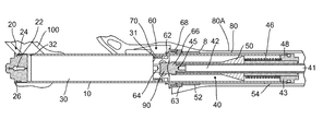
- FIG. 1 is a side elevational view in partial cross-section of a bicycle fork including the present invention seal
- the fork consists of a telescoping assembly with the spring system using a compressed air chamber 30 .
- a compression rod 42 moves with a wheel to which the fork is attached when a bump is encountered by the wheel. This upward movement of the compression rod 40 translates to a piston 64 , compressing the air chamber 30 , resulting in a higher pressure.
Abstract
Description
Claims (8)
Priority Applications (3)
| Application Number | Priority Date | Filing Date | Title |
|---|---|---|---|
| US13/481,109 US9132881B2 (en) | 2012-05-25 | 2012-05-25 | Rubber isolation system incorporated between the compression rod and the gas spring assembly of a bicycle fork |
| TW102118103A TWI657956B (en) | 2012-05-25 | 2013-05-22 | Rubber isolation system incorporated between the compression rod and the gas spring assembly of a bicycle fork |
| US14/823,857 US9988124B2 (en) | 2012-05-25 | 2015-08-11 | Suspension assembly |
Applications Claiming Priority (1)
| Application Number | Priority Date | Filing Date | Title |
|---|---|---|---|
| US13/481,109 US9132881B2 (en) | 2012-05-25 | 2012-05-25 | Rubber isolation system incorporated between the compression rod and the gas spring assembly of a bicycle fork |
Related Child Applications (1)
| Application Number | Title | Priority Date | Filing Date |
|---|---|---|---|
| US14/823,857 Continuation US9988124B2 (en) | 2012-05-25 | 2015-08-11 | Suspension assembly |
Publications (2)
| Publication Number | Publication Date |
|---|---|
| US20130313803A1 US20130313803A1 (en) | 2013-11-28 |
| US9132881B2 true US9132881B2 (en) | 2015-09-15 |
Family
ID=49620994
Family Applications (2)
| Application Number | Title | Priority Date | Filing Date |
|---|---|---|---|
| US13/481,109 Expired - Fee Related US9132881B2 (en) | 2012-05-25 | 2012-05-25 | Rubber isolation system incorporated between the compression rod and the gas spring assembly of a bicycle fork |
| US14/823,857 Active 2032-11-20 US9988124B2 (en) | 2012-05-25 | 2015-08-11 | Suspension assembly |
Family Applications After (1)
| Application Number | Title | Priority Date | Filing Date |
|---|---|---|---|
| US14/823,857 Active 2032-11-20 US9988124B2 (en) | 2012-05-25 | 2015-08-11 | Suspension assembly |
Country Status (2)
| Country | Link |
|---|---|
| US (2) | US9132881B2 (en) |
| TW (1) | TWI657956B (en) |
Cited By (6)
| Publication number | Priority date | Publication date | Assignee | Title |
|---|---|---|---|---|
| US10221914B2 (en) | 2008-07-24 | 2019-03-05 | Fox Factory, Inc. | Vehicle suspension damper |
| US10384509B2 (en) * | 2008-03-19 | 2019-08-20 | Fox Factory, Inc. | Methods and apparatus for vehicle suspension having multiple gas volumes |
| US10408295B2 (en) | 2008-03-19 | 2019-09-10 | Fox Factory, Inc. | Methods and apparatus for combined variable damping and variable spring rate suspension |
| US10933940B2 (en) * | 2017-05-18 | 2021-03-02 | Dt Swiss Inc. | Shock device in particular for bicycles |
| US11884359B2 (en) | 2022-02-25 | 2024-01-30 | Sram, Llc | Bicycle suspension components |
| US11951793B2 (en) | 2022-04-18 | 2024-04-09 | Fox Factory, Inc. | Methods and apparatus for vehicle suspension having multiple gas volumes |
Families Citing this family (8)
| Publication number | Priority date | Publication date | Assignee | Title |
|---|---|---|---|---|
| JP5977665B2 (en) * | 2012-12-14 | 2016-08-24 | Kyb株式会社 | Front fork |
| CN106476965B (en) * | 2016-09-30 | 2021-03-16 | 天津市众兴邦科技发展有限公司 | Screw-in extrusion adjusting type front fork |
| CN107914814B (en) * | 2016-10-09 | 2020-04-07 | 台湾穗高工业股份有限公司 | Shock absorbing device for front fork of bicycle |
| USD860062S1 (en) * | 2018-02-08 | 2019-09-17 | Trvstper, Inc. | Cycle suspension assembly |
| USD861542S1 (en) * | 2018-02-08 | 2019-10-01 | Trvstper, Inc. | Cycle suspension assembly |
| USD860061S1 (en) * | 2018-02-08 | 2019-09-17 | Trvstper, Inc. | Cycle suspension assembly |
| CN108482559A (en) * | 2018-05-25 | 2018-09-04 | 张学田 | Bicycle gas control stretching handle |
| CN110905959B (en) * | 2018-09-14 | 2024-01-26 | 优维士(天津)车业有限公司 | Mountain bike shock-absorbing rod with light weight |
Citations (15)
| Publication number | Priority date | Publication date | Assignee | Title |
|---|---|---|---|---|
| US4331224A (en) * | 1979-03-22 | 1982-05-25 | Honda Giken Kogyo Kabushiki Kaisha | Hydraulic shock absorber for vehicles |
| US4561669A (en) * | 1982-12-30 | 1985-12-31 | Simons Stephen W | Motorcycle fork |
| US4791712A (en) * | 1986-09-02 | 1988-12-20 | General Motors Corporation | Modular piston with high strength tensile joint and method of manufacture |
| US6095541A (en) * | 1997-07-16 | 2000-08-01 | Rockshox, Inc. | Adjustable gas spring suspension system |
| US6105988A (en) * | 1997-07-16 | 2000-08-22 | Rockshox, Inc. | Adjustable suspension system having positive and negative springs |
| US20030051957A1 (en) * | 2001-09-14 | 2003-03-20 | Rene Lemieux | Shock absorber with a floating piston |
| US20040017035A1 (en) * | 2002-06-29 | 2004-01-29 | Christian Treder | Damper support having a contoured end face for a shock absorber of a motor vehicle |
| US20080041681A1 (en) * | 2006-08-18 | 2008-02-21 | Sram Corporation | Bicycle suspension system |
| US7451860B2 (en) * | 2004-04-20 | 2008-11-18 | Thyssenkrupp Bilstein Gmbh | Shock absorber with amplitude damping |
| US20090001684A1 (en) * | 2007-06-29 | 2009-01-01 | Specialized Bicycle Components, Inc. | Bicycle suspension assembly |
| US7837180B2 (en) * | 2005-09-14 | 2010-11-23 | Sram, Llc | Gas spring suspension system |
| US20100314209A1 (en) * | 2009-06-15 | 2010-12-16 | Gonzalez Jose L | Bicycle shock assemblies with plunger operated valve arrangement |
| US20110083930A1 (en) * | 2009-10-13 | 2011-04-14 | Andrew Laird | Self-regulating suspension |
| US20110187076A1 (en) * | 2010-02-01 | 2011-08-04 | Trek Bicycle Corporation | Bicycle Air Shock Assemblies With Tunable Suspension Performance |
| US8033368B2 (en) * | 2001-07-02 | 2011-10-11 | Fox Factory, Inc. | Bicycle fork having lock-out, blow-off, and adjustable blow-off threshold |
Family Cites Families (2)
| Publication number | Priority date | Publication date | Assignee | Title |
|---|---|---|---|---|
| US2212759A (en) | 1937-10-25 | 1940-08-27 | Chrysler Corp | Shock absorber |
| JPS5753139U (en) * | 1980-09-11 | 1982-03-27 |
-
2012
- 2012-05-25 US US13/481,109 patent/US9132881B2/en not_active Expired - Fee Related
-
2013
- 2013-05-22 TW TW102118103A patent/TWI657956B/en active
-
2015
- 2015-08-11 US US14/823,857 patent/US9988124B2/en active Active
Patent Citations (15)
| Publication number | Priority date | Publication date | Assignee | Title |
|---|---|---|---|---|
| US4331224A (en) * | 1979-03-22 | 1982-05-25 | Honda Giken Kogyo Kabushiki Kaisha | Hydraulic shock absorber for vehicles |
| US4561669A (en) * | 1982-12-30 | 1985-12-31 | Simons Stephen W | Motorcycle fork |
| US4791712A (en) * | 1986-09-02 | 1988-12-20 | General Motors Corporation | Modular piston with high strength tensile joint and method of manufacture |
| US6095541A (en) * | 1997-07-16 | 2000-08-01 | Rockshox, Inc. | Adjustable gas spring suspension system |
| US6105988A (en) * | 1997-07-16 | 2000-08-22 | Rockshox, Inc. | Adjustable suspension system having positive and negative springs |
| US8033368B2 (en) * | 2001-07-02 | 2011-10-11 | Fox Factory, Inc. | Bicycle fork having lock-out, blow-off, and adjustable blow-off threshold |
| US20030051957A1 (en) * | 2001-09-14 | 2003-03-20 | Rene Lemieux | Shock absorber with a floating piston |
| US20040017035A1 (en) * | 2002-06-29 | 2004-01-29 | Christian Treder | Damper support having a contoured end face for a shock absorber of a motor vehicle |
| US7451860B2 (en) * | 2004-04-20 | 2008-11-18 | Thyssenkrupp Bilstein Gmbh | Shock absorber with amplitude damping |
| US7837180B2 (en) * | 2005-09-14 | 2010-11-23 | Sram, Llc | Gas spring suspension system |
| US20080041681A1 (en) * | 2006-08-18 | 2008-02-21 | Sram Corporation | Bicycle suspension system |
| US20090001684A1 (en) * | 2007-06-29 | 2009-01-01 | Specialized Bicycle Components, Inc. | Bicycle suspension assembly |
| US20100314209A1 (en) * | 2009-06-15 | 2010-12-16 | Gonzalez Jose L | Bicycle shock assemblies with plunger operated valve arrangement |
| US20110083930A1 (en) * | 2009-10-13 | 2011-04-14 | Andrew Laird | Self-regulating suspension |
| US20110187076A1 (en) * | 2010-02-01 | 2011-08-04 | Trek Bicycle Corporation | Bicycle Air Shock Assemblies With Tunable Suspension Performance |
Cited By (10)
| Publication number | Priority date | Publication date | Assignee | Title |
|---|---|---|---|---|
| US10384509B2 (en) * | 2008-03-19 | 2019-08-20 | Fox Factory, Inc. | Methods and apparatus for vehicle suspension having multiple gas volumes |
| US10408295B2 (en) | 2008-03-19 | 2019-09-10 | Fox Factory, Inc. | Methods and apparatus for combined variable damping and variable spring rate suspension |
| US11181163B2 (en) | 2008-03-19 | 2021-11-23 | Fox Factory, Inc. | Methods and apparatus for combined variable damping and variable spring rate suspension |
| US11312203B2 (en) | 2008-03-19 | 2022-04-26 | Fox Factory, Inc. | Methods and apparatus for vehicle suspension having multiple gas volumes |
| US10221914B2 (en) | 2008-07-24 | 2019-03-05 | Fox Factory, Inc. | Vehicle suspension damper |
| US10612618B2 (en) | 2008-07-24 | 2020-04-07 | Fox Factory, Inc. | Vehicle suspension damper |
| US11041537B2 (en) | 2008-07-24 | 2021-06-22 | Fox Factory, Inc. | Vehicle suspension damper |
| US10933940B2 (en) * | 2017-05-18 | 2021-03-02 | Dt Swiss Inc. | Shock device in particular for bicycles |
| US11884359B2 (en) | 2022-02-25 | 2024-01-30 | Sram, Llc | Bicycle suspension components |
| US11951793B2 (en) | 2022-04-18 | 2024-04-09 | Fox Factory, Inc. | Methods and apparatus for vehicle suspension having multiple gas volumes |
Also Published As
| Publication number | Publication date |
|---|---|
| TWI657956B (en) | 2019-05-01 |
| US20150344101A1 (en) | 2015-12-03 |
| TW201402387A (en) | 2014-01-16 |
| US9988124B2 (en) | 2018-06-05 |
| US20130313803A1 (en) | 2013-11-28 |
Similar Documents
| Publication | Publication Date | Title |
|---|---|---|
| US9132881B2 (en) | Rubber isolation system incorporated between the compression rod and the gas spring assembly of a bicycle fork | |
| US7837180B2 (en) | Gas spring suspension system | |
| TWI495440B (en) | Cane | |
| US9765842B2 (en) | Suspension device | |
| CA2627817A1 (en) | Single cylinder type hydraulic shock absorber for vehicle | |
| CN209671499U (en) | A kind of automobile absorber with multiplex buffer gear | |
| US9957008B1 (en) | Bicycle seatpost structure | |
| US10500915B2 (en) | Shock absorber incorporating a floating piston | |
| US9731574B2 (en) | Shock absorber gas spring seal | |
| CN107914814B (en) | Shock absorbing device for front fork of bicycle | |
| US11299232B2 (en) | Suspension system with a tunable air spring | |
| CN110005744A (en) | A kind of double-piston magnetic rheological liquid damper | |
| CN113799899B (en) | Bicycle suspension component | |
| US10144482B2 (en) | Shock absorber | |
| CN203979253U (en) | A kind of automobile-used damping device | |
| CN203161960U (en) | Multi-spring combined shock absorber | |
| CN208669925U (en) | A kind of high-tensile structure of motorcycle vibration absorber | |
| CN213393293U (en) | Rebound button adjusting mechanism of motorcycle front axle shock absorber | |
| CN109882535B (en) | Air pressure balancing device for bicycle shock absorber | |
| TWI836455B (en) | Bicycle suspension components | |
| CN220518494U (en) | Bicycle shock attenuation front fork structure | |
| CN210290574U (en) | Double-cylinder double-air-chamber hydro-pneumatic spring | |
| CN206129967U (en) | Atmospheric pressure type tubular bumper shock absorber that stretches out and draws back | |
| TWM548659U (en) | Bicycle stem tube cushion and shock absorption structure | |
| CN105673770A (en) | Spring and air bag type damper of electric vehicle |
Legal Events
| Date | Code | Title | Description |
|---|---|---|---|
| AS | Assignment |
Owner name: HAYES BICYCLE GROUP, INC., WISCONSIN Free format text: ASSIGNMENT OF ASSIGNORS INTEREST;ASSIGNOR:KWATERSKI, EDWARD C.;REEL/FRAME:028271/0951 Effective date: 20120525 |
|
| AS | Assignment |
Owner name: BMO HARRIS BANK N.A., SUCCESSOR-BY-MERGER TO M&I M Free format text: SECURITY INTEREST;ASSIGNOR:HAYES BICYCLE GROUP, INC.;REEL/FRAME:032853/0963 Effective date: 20140508 |
|
| STCF | Information on status: patent grant |
Free format text: PATENTED CASE |
|
| FEPP | Fee payment procedure |
Free format text: MAINTENANCE FEE REMINDER MAILED (ORIGINAL EVENT CODE: REM.); ENTITY STATUS OF PATENT OWNER: LARGE ENTITY |
|
| LAPS | Lapse for failure to pay maintenance fees |
Free format text: PATENT EXPIRED FOR FAILURE TO PAY MAINTENANCE FEES (ORIGINAL EVENT CODE: EXP.); ENTITY STATUS OF PATENT OWNER: LARGE ENTITY |
|
| STCH | Information on status: patent discontinuation |
Free format text: PATENT EXPIRED DUE TO NONPAYMENT OF MAINTENANCE FEES UNDER 37 CFR 1.362 |
|
| FP | Expired due to failure to pay maintenance fee |
Effective date: 20190915 |
|
| AS | Assignment |
Owner name: TOWN BANK, N.A., WISCONSIN Free format text: SECURITY INTEREST;ASSIGNORS:HB PERFORMANCE SYSTEMS HOLDINGS LLC;HB PERFORMANCE SYSTEMS, INC.;HAYES BICYCLE GROUP, INC.;AND OTHERS;REEL/FRAME:052705/0836 Effective date: 20200518 |
|
| AS | Assignment |
Owner name: HAYES BICYCLE GROUP, INC., WISCONSIN Free format text: RELEASE BY SECURED PARTY;ASSIGNOR:BMO HARRIS BANK N.A.;REEL/FRAME:053701/0815 Effective date: 20200518 Owner name: HB POWERSPORTS GROUP, INC., WISCONSIN Free format text: RELEASE BY SECURED PARTY;ASSIGNOR:BMO HARRIS BANK N.A.;REEL/FRAME:053701/0815 Effective date: 20200518 Owner name: HB PERFORMANCE SYSTEMS, INC., WISCONSIN Free format text: RELEASE BY SECURED PARTY;ASSIGNOR:BMO HARRIS BANK N.A.;REEL/FRAME:053701/0815 Effective date: 20200518 |