US9122610B2 - OS friendly microprocessor architecture - Google Patents
OS friendly microprocessor architecture Download PDFInfo
- Publication number
- US9122610B2 US9122610B2 US14/029,053 US201314029053A US9122610B2 US 9122610 B2 US9122610 B2 US 9122610B2 US 201314029053 A US201314029053 A US 201314029053A US 9122610 B2 US9122610 B2 US 9122610B2
- Authority
- US
- United States
- Prior art keywords
- cache
- controller
- module
- bank
- memory
- Prior art date
- Legal status (The legal status is an assumption and is not a legal conclusion. Google has not performed a legal analysis and makes no representation as to the accuracy of the status listed.)
- Expired - Fee Related, expires
Links
Images


Classifications
-
- G—PHYSICS
- G06—COMPUTING OR CALCULATING; COUNTING
- G06F—ELECTRIC DIGITAL DATA PROCESSING
- G06F12/00—Accessing, addressing or allocating within memory systems or architectures
- G06F12/02—Addressing or allocation; Relocation
- G06F12/08—Addressing or allocation; Relocation in hierarchically structured memory systems, e.g. virtual memory systems
- G06F12/0802—Addressing of a memory level in which the access to the desired data or data block requires associative addressing means, e.g. caches
- G06F12/0844—Multiple simultaneous or quasi-simultaneous cache accessing
- G06F12/0846—Cache with multiple tag or data arrays being simultaneously accessible
-
- G—PHYSICS
- G06—COMPUTING OR CALCULATING; COUNTING
- G06F—ELECTRIC DIGITAL DATA PROCESSING
- G06F12/00—Accessing, addressing or allocating within memory systems or architectures
- G06F12/02—Addressing or allocation; Relocation
- G06F12/08—Addressing or allocation; Relocation in hierarchically structured memory systems, e.g. virtual memory systems
- G06F12/0802—Addressing of a memory level in which the access to the desired data or data block requires associative addressing means, e.g. caches
- G06F12/0844—Multiple simultaneous or quasi-simultaneous cache accessing
- G06F12/0855—Overlapped cache accessing, e.g. pipeline
-
- G—PHYSICS
- G06—COMPUTING OR CALCULATING; COUNTING
- G06F—ELECTRIC DIGITAL DATA PROCESSING
- G06F12/00—Accessing, addressing or allocating within memory systems or architectures
- G06F12/02—Addressing or allocation; Relocation
- G06F12/08—Addressing or allocation; Relocation in hierarchically structured memory systems, e.g. virtual memory systems
- G06F12/0802—Addressing of a memory level in which the access to the desired data or data block requires associative addressing means, e.g. caches
- G06F12/0875—Addressing of a memory level in which the access to the desired data or data block requires associative addressing means, e.g. caches with dedicated cache, e.g. instruction or stack
-
- G—PHYSICS
- G06—COMPUTING OR CALCULATING; COUNTING
- G06F—ELECTRIC DIGITAL DATA PROCESSING
- G06F9/00—Arrangements for program control, e.g. control units
- G06F9/06—Arrangements for program control, e.g. control units using stored programs, i.e. using an internal store of processing equipment to receive or retain programs
- G06F9/30—Arrangements for executing machine instructions, e.g. instruction decode
- G06F9/38—Concurrent instruction execution, e.g. pipeline or look ahead
-
- Y02B60/1225—
-
- Y—GENERAL TAGGING OF NEW TECHNOLOGICAL DEVELOPMENTS; GENERAL TAGGING OF CROSS-SECTIONAL TECHNOLOGIES SPANNING OVER SEVERAL SECTIONS OF THE IPC; TECHNICAL SUBJECTS COVERED BY FORMER USPC CROSS-REFERENCE ART COLLECTIONS [XRACs] AND DIGESTS
- Y02—TECHNOLOGIES OR APPLICATIONS FOR MITIGATION OR ADAPTATION AGAINST CLIMATE CHANGE
- Y02D—CLIMATE CHANGE MITIGATION TECHNOLOGIES IN INFORMATION AND COMMUNICATION TECHNOLOGIES [ICT], I.E. INFORMATION AND COMMUNICATION TECHNOLOGIES AIMING AT THE REDUCTION OF THEIR OWN ENERGY USE
- Y02D10/00—Energy efficient computing, e.g. low power processors, power management or thermal management
Definitions
- the present microprocessor architecture 100 invention parallelizes the operations typically used in software by an operating system to significantly improve the performance of an operating system context switch.
- a second benefit of the new architecture is hardware based information assurance.
- FIG. 1 introduces the Operating System Friendly Microprocessor Architecture 100 .
- the processor memory and bus architecture is an extended Harvard architecture.
- a Harvard architecture uses separate busses and memory banks for program instructions and data.
- the architecture consists of 4 DMA/cache controller banks connected to a microprocessor pipeline 190 .
- the OS Friendly Architecture 100 is essentially a switched set of cache memory banks in a pipeline configuration.
- the pipeline DMA/Cache Banks and Controllers in FIG. 1 100 provide higher performance and lower power requirements through pipelining and parallelism.
- OS information assurance for data is implemented in hardware.
- the processor 100 provides hardware level information assurance.
- a table 700 listing all possible library function calls the application software may use, is created. Each library function call lists a set of limits. Exceeding the limits either requires higher than user access or raises an exception.
- the OS Friendly Architecture 100 (1) significantly reduces the cost of an operating system context switch (1 to 10 CPU cycles is possible); (2) provides hardware level information assurance; and (3) reduces processor power requirements.
- FIG. 1 OS Friendly Processor Architecture
- FIG. 2 Data, Instruction, and Register Cache Bank Controllers and Cache Banks
- FIG. 3 Peline State Cache Bank Controllers and Cache Banks
- FIG. 4 A Data, Instruction, and Register Cache Banks
- FIG. 4 B Pipeline State Cache Banks
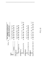
- FIG. 5 Context Switch Timing Diagram
- FIG. 6 Cache Bank and Memory Cell Hardware Information Assurance
- FIG. 7 Library Function Call Table
- FIG. 8 Constructional Processor Architecture Model
- FIG. 9 OS Friendly Processor Architecture Model
- FIG. 10 Component-level Timing Diagram for Conventional Architecture
- FIG. 11 Time-Optimized OS Friendly Architecture Timing Diagram
- FIG. 12 OS Friendly Architecture Zero Overhead Thread Context Switch Timing Diagram
- FIG. 1 introduces the Operating System Friendly Microprocessor Architecture 100 .
- the processor memory and bus architecture 100 is an extended Harvard architecture.
- the OS Friendly Architecture 100 is essentially a switched set of cache memory banks 250 I, 250 D, 250 R, and 350 in a multiple pipeline configuration. ( FIG. 2 and FIG. 3 )
- the DMA/Cache Controller Banks 120 I, 120 D, 120 R, and 130 connect to execution pipeline 190 through busses 128 I, 128 D, 128 R, and 138 .
- Level 1/Level 2 caching 110 I, 110 D, 110 R, and 110 P connect to external cache and external memory 105 I, 105 D, 105 R, and 105 P through busses 106 I, 106 D, 106 R, and 106 P.
- the OS Friendly Architecture 100 can also be modified to use a unified external memory architecture similar to a modified Harvard architecture (internal separate caches for instructions and data, and a unified external memory).
- a program instruction memory module 102 I has a first external cache and memory module 105 I, a first internal cache 110 I, a first DMA controller 122 I, and a first cache controller and cache bank module 126 I ( FIG. 1 ).
- the first external cache and memory module 105 I connects to the first internal cache 110 I with the first internal cache 110 I connecting to first DMA controller 122 I.
- First DMA controller 122 I connects to the first cache controller and cache bank module 126 I.
- a data memory module 102 D has a second external cache and memory module 105 D, a second internal cache 110 D, a second DMA controller 122 D, and a second cache controller and cache bank module 126 D.
- the second external cache and memory module 105 D connects to the second internal cache 110 D.
- the second internal cache 110 D connects to the second DMA controller 122 D, with the second DMA controller 122 D connecting to the second cache controller and cache bank module 126 D.
- a register memory module 102 R has a third external cache and memory module 105 R, a third internal cache 110 R, a third DMA controller 122 R, and a third cache controller and cache bank module 126 R.
- the third external cache and memory module 105 R connects to the third internal cache 110 R.
- the third internal cache 110 R connects to the third DMA controller 122 R and the third DMA controller 122 R connects to the third cache controller and cache bank module 126 R.
- a pipeline state memory module 102 P has a fourth external cache and memory module 105 P, a fourth internal cache 110 P, a fourth DMA controller 132 , and a fourth cache controller and cache bank module 136 ( FIG. 1 ).
- the fourth external cache and memory module 105 P connects to the fourth internal cache 110 P.
- the fourth internal cache 110 P connects to the fourth DMA controller 132 , with the fourth DMA controller 132 connecting to the fourth cache controller and cache bank module 126 R.
- the microprocessor pipeline 190 connects to the first cache controller and cache bank module 126 I, to the second cache controller and cache bank module 126 D, to the third cache controller and cache bank module 126 R, and to the fourth cache controller and cache bank module 136 .
- the first DMA controller 122 I and the first cache controller and cache bank module 126 I communicate with the microprocessor pipeline 190 for executing instructions while the first DMA controller 122 I and the first cache controller and cache bank module 126 I utilize the first internal cache 110 I and first external cache and memory module 105 I for memory storage.
- the second DMA controller 122 D and the second cache controller and cache bank module 126 D communicate with the microprocessor pipeline 190 for data operations while the second DMA controller 122 D and the second cache controller and cache bank module 126 D utilize the second internal cache 110 D and second external cache and memory module 105 D for memory storage.
- the third DMA controller 122 R and the third cache controller and cache bank module 126 R communicate with the microprocessor pipeline 190 for register operations while the third DMA controller 122 R and the third cache controller and the cache bank module 126 R utilize the third internal cache 110 R and the third external cache and memory module 105 R for memory storage ( FIG. 1 ).
- the fourth DMA controller 132 and the fourth cache controller and cache bank module 136 communicate with the microprocessor pipeline 190 for pipeline state operations while the fourth DMA controller 132 and the fourth cache controller and cache bank module 136 utilize the fourth internal cache 110 P and the fourth external cache and memory module 105 P for memory storage.
- the instruction 126 I, data 126 D, and register 126 R cache bank controllers are configured to only write one block at a time from/to the processor pipeline 190 .
- the DMA/Cache Bank Controllers 120 120 I, 120 D, and 120 R
- the pipeline caching structure also allows for the execution pipeline 190 to run at full speed while hardware controllers provide cache to memory (L1, L2, L3 etc. level caches and main memory) copy operations in parallel.
- a fully parallel DMA/cache bank controller is shown; however, the fully parallel version is significantly more complex, and in 120 ( 120 I, 120 D, and 120 R) cache memory size is more important than fully parallel.
- the instruction, data, and register cache bank controllers can also be configured for fully parallel using DMA/cache controller bank 130 .
- a typical process is allowed to run for milliseconds before context switching 500 ( 500 A, 500 B, 500 C, . . . ) to the next process.
- the DMA Controller/Cache Memory Banks in ( 120 I, 120 D, 120 R, and 130 ) can complete background copy operations on the order of milliseconds, the processor 100 does not “see” any of the background operations. Since memory ( 110 I, 110 D, 110 R, and 110 P) and ( 105 I, 105 D, 105 R, and 105 P) can now run at a much lower clock frequency, significant power savings results without decreasing processor performance.
- FIG. 5 illustrates the write and load cache bank operations for processes n ⁇ 1, n, and n+1.
- process identification numbers would be arbitrary.
- the load (read) and write cycles for each cache bank 126 I, 126 D, 126 R, and 136 are shown. This is a worst case example showing cache writes and loads for each context switch in 500 . Data locality would limit the number of writes and loads resulting in more time to copy memory, allowing for more power savings.
- Fully parallel memory copy operations for pipeline stage cache bank 130 are shown for block 136 .
- the “B(•)” notation refers to cache bank number (•) or a set of bank numbers (•)'s.
- the instruction, data, register, and pipeline state cache controller banks consist of cache banks in (1) active use ( 250 I.B(act), 250 D.B(act), 250 R.B(act), and 350 .B(act)) by execution pipeline 190 , (2) inactive cache banks ( 250 I.B(ina), 250 D.B(ina), 250 R.B(ina), and 350 .B(ina)) not in use by execution pipeline 190 and not in use by DMA Controllers ( 122 I, 122 D, 122 R, and 132 ), and (3) swapping set cache banks ( 250 I.B(swp), 250 D.B(swp), 250 R.B(swp), and 350 .B(swp)) in use by DMA Controllers ( 122 I, 122 D, 122 R, and 132 ).
- FIG. 5 illustrates the background DMA controller 122 I, 122 D, 122 R, and 132 operations that run in parallel with the execution pipeline 190 .
- the active pipeline state cache banks 350 .B(act) are copied in parallel into the plurality of pipeline latches 194 A, 194 B, 194 C, . . . .
- the pipeline state latches 194 A, 194 B, 194 C, . . . are copied in parallel to the active pipeline state cache bank 350 .B(act).
- the inactive cache banks 250 I.B(ina), 250 D.B(ina), 250 R.B(ina), and 350 .B(ina) are idle.
- the swapping set cache banks 250 I.B(swp), 250 D.B(swp), 250 R.B(swp), and 350 .B(swp) are copied to L1 level caching 110 I, 110 D, 110 R, and 110 P.
- the swapping set cache banks 250 I.B(swp), 250 D.B(swp), 250 R.B(swp), and 350 .B(swp) for process n+1 are loaded into cache banks 250 I.B(m), 250 D.B(m), 250 R.B(m), and 350 .B(m) to prepare to execute process n+1 during the next context time 500 C- 500 D.
- the cache banks 250 I.B(m), 250 D.B(m), 250 R.B(m), and 350 .B(m) are set to active ( 250 I.B(act), 250 D.B(act), 250 R.B(act), and 350 .B(act) are now in use by execution pipeline 190 ).
- OS information assurance for data is implemented in hardware.
- the architecture 100 provides hardware level information assurance.
- the notation (I, D, R) shows a plurality of elements (for example cache banks: 120 I, 120 D, and 120 R).
- FIG. 6 illustrates hardware level information assurance.
- Each cache controller bank 126 I, 126 D, 126 R, and 136 ( FIGS. 1 , 2 , 3 and 4 A and 4 B) has a set of OS level permission bits 610 . m .
- Memory type field 618 . m in cache banks ( 126 I, 126 D, 126 R, and 136 ) is used to define data types; for example, data space, stack space, heap space, integer, floating point, etc. Only the OS has permission to access and modify cache bank permission bits 610 (all 610 . m references).
- OS level access to cache controller banks 126 I, 126 D, 126 R, and 136 is divided into access layers: layer — 0, 614 .
- Each cache memory bank has permission bits for each memory cell 620 .( m, n ) where m is the cache bank number, and n is the memory cell (memory address).
- Each cache bank memory cell 620 .( m, n ) has permission bits for the OS layers 622 .( m, n ), Process (User Level) 630 .( m, n ), and Applications 632 .( m, n ).
- the OS permission bits are further divided in OS layers: layer — 0, 624 .( m, n ), layer — 1, 625 .( m, n ), etc. Additional permission bits can easily be incorporated herein by those skilled in OS and microprocessor arts.
- Permission bit Index Register I/O (IRegIO) 650 E allows OS to provide an index register pointing to an input/output (I/O) port or I/O memory address.
- the IRegIO bit 650 E “locks out” the register 640 .( m, n ), or cache bank ( 250 I, 250 D, 250 R or 350 ) from being read, written to, or modified. The running process is prevented from accessing the contents of the register; however, the process can use the register to read/write I/O.
- Registers 640 .( m, n ), can be used to define data types using two registers for minimum value and maximum value.
- FIG. 7 extends the principal of least privilege to the library function call level.
- a table 700 listing all possible library function calls the application software may use is created.
- Each possible library function call 701 , 702 , 703 , . . . is listed with typical 710 , moderate load 720 , maximum load 730 , etc. lower and upper limits.
- the OpenFile (•) library function call 702 privilege limits If the minimum number of open files is 0, the lower limits for cases 711 , 721 , and 731 is 0. If the typically user will only have 5 files open at a time, the upper limit for typical 712 is 5. The upper limit for a moderate load is found in 722 .
- Maximum load upper limit 732 specifies the maximum number of files that may be open at a time.
- Exceeding the upper limits in 712 , 722 , and 732 can be set to (1) require higher than user level privileges, or to (2) generate an exception.
- the digital signature in 750 provides authentication of the library function call table and its permission settings 710 , 720 , 730 , etc.
- the OS Friendly Microprocessor Architecture 100 offers new opportunities for increased performance and decreased power consumption by providing hardware structures specifically selected for optimizing system-level operations frequently instantiated by an OS. Sections [0031] through [0039] give a first-order approximation of the potential benefits in OS Friendly Microprocessor Architecture's 100 performance. Sections [0040] through [0063] give a first-order approximation of power reductions offered by the new design 100 . A speedup is estimated for a zero overhead context switch in section [0064].
- FIG. 8 is the execution pipeline for conventional architecture and FIG. 9 demonstrates the modeled execution pipeline of FIG. 8 in present invention.
- FIGS. 10 , 11 and 12 the estimated time for a context switch for both a conventional architecture 800 and the new OS Friendly Architecture (OSFA) 100 are compared.
- OSFA OS Friendly Architecture
- FIGS. 8 through 12 The high-level representations of the conventional 800 and improved architectures 100 of the present invention are further explained below concerning FIGS. 8 through 12 .
- These figures assume the following architectural characteristics.
- PS The labels inside the pipeline stages (labeled “PS” 820 in FIG. 8 and FIG. 9 ) refer to the stages to which the following sections reference (EX: Execution Stage 830 , MEM: Memory Access Stage 840 , and WB: Writeback Stage 850 ).
- EX Execution Stage 830
- MEM Memory Access Stage 840
- WB Writeback Stage 850
- the pipelines in both architectures, OS Friendly 100 and conventional 800 operate at a fixed voltage V P — H with clock period t S .
- the Register File Set (RFS) active cache bank 250 R.B(act) and the Pipeline State Cache Sets (PSCS) active cache bank 350 .B(act) normally operate at voltage V R — H with clock period t S .
- the OSFA 100 can dynamically scale down both the voltages and clock rates of the inactive and swapping components. The voltage of these components can be reduced to some value V L , while the clock period of these components can be reduced to some value t L .
- FIG. 5 presents a worst case timing diagram for the OS Friendly Architecture assuming swapping set cache banks ( 250 I.B(swp), 250 D.B(swp), 250 R.B(swp)) and 350 .B(swp) must be loaded and written for every context switch 500 . Data locality will significant reduce the number of cache bank memory copy operations.
- All components of the conventional architecture 800 operate with the short clock period t H .
- the OSFA 100 pipeline 190 M (model of pipeline 190 used to compare 100 to conventional 800 ) also operates with clock period t S .
- the RFS cache banks 250 R.B(m) and the PSCS cache banks 350 .B(m) are each divided into three sets: active, inactive, and swapping set.
- One of the register cache banks 250 .B(act) is active and one of the pipeline state caches 225 .AP is active.
- the active components 250 .B(act) and 350 .B(act) operate with clock period t S
- the swapping components 250 .B(swp) and 350 .B(swp) operate with the longer clock period t L
- the inactive components 250 .B(ina) and 350 .B(ina) are idle.
- the steps involved in a context switch for the conventional processor 800 include the following:
- step 1 will require s clock ticks, and hence s ⁇ t S time.
- step 2 writing each register file out to memory—requires reading each register value into the EX stage 830 , moving it into the MEM stage 840 , and then flushing it out to memory 850 .
- This is three ticks for each register value, but since the operations can be performed in a pipelined fashion, we approximate this as r ⁇ t S time total for all r registers.
- Step 3 requires filling up the pipeline to retrieve register values from memory ⁇ requiring s ticks ⁇ then writing each value back to the register file in the writeback stage 850 for a total of (s+r) t S time.
- Step 4 is filling the pipeline back up with values from the register file, but this can be pipelined with the register file refill and hence is already accounted for.
- Step 5 takes some unknown amount of time t OS — NORMAL that is dependent on the OS design.
- Steps 6 and 7 are similar to steps 1 and 2, which again require s ⁇ t S time and r t S time, respectively.
- Step 8 is like step 3 which requires (s+r) t S time
- step 9 is like step 4 which is accounted for in this time.
- t CS CONV st s + rt s + ( s + r ) ⁇ t s + t OS NORMAL + st s + rt s + ( s + r ) ⁇ t s ( 1 )
- t CS CONV 4 ⁇ t s ⁇ ( r + s ) + t OS NORMAL ( 2 )
- the OSFA 100 performs the following steps in a context switch:
- step 1 all pipeline stages flush state to the active pipeline state cache 350 .B(act) simultaneously, and hence this requires only one tick at the high clock rate for a time of t S .
- step 2 takes also a single tick to switch to the next active cache (next process' active pipeline state cache bank 350 .B(act)) and next active register file (next process' active register cache bank 250 R.B(act)).
- step 3 takes s ticks for the pipeline state cache 350 .B(m) and r ticks for the register file 250 .B(m).
- step 3 can be completed in less time (if, for the time being, we ignore cache misses and contention), as the pipeline state and register file are relatively small, while the OS must generally perform several system operations before switching back to a user-level process.
- Step 4 is the reverse of step 1, so it requires only a single tick.
- Step 5 still takes t OS — NORMAL as with the conventional architecture, and step 6 takes a single tick like step 1.
- Step 7 is the reverse of step 3 and requires the same amount of time. But again, these steps can be performed in parallel with those of 4-6.
- Step 8 is the same as step 2, and step 9 is the same as step 4.
- Each of these takes one tick.
- the total time, Equation (3), for the context switch, t CS — OFA , for OSFA 100 is found in Equation (4).
- t CS — OFA t S +t S +t S +t OS — NORMAL +t S +t S +t S (3)
- t CS — OFA 6 t S +t OS — NORMAL (4)
- FIG. 10 and FIG. 11 show two component-level timing diagrams: one for the conventional architecture 800 during a context switch, and another for the OSFA 100 during a context switch 500 A, 500 B, 500 C, . . . .
- the diagram shows the OSFA 100 executing the context switch in less time than the conventional architecture 800 , as previously described.
- the parallelism requires that more components are active during execution, and so its power consumption relative to the conventional architecture is not immediately clear.
- Equation (7) can be used to estimate the relative dynamic power consumption.
- V H the voltage of all components is assumed to be the same value.
- the activity values, A P , and the capacitance values, C R , of the pipelines are assumed to be the same for both architectures. Similarly, these values are assumed to be the same for all register files, and are referred to as A R and C R for the activity levels and the output capacitances, respectively.
- a R and C R for the activity levels and the output capacitances, respectively.
- P D_CONV P D_Pipeline + P D_RegisterFil ⁇ e ( 8 )
- P D_CONV ⁇ P ⁇ V P_H 2 ⁇ 1 t s + ⁇ R ⁇ V R_H 2 ⁇ 1 t s ( 9 )
- the average power consumption of the pipeline and active storage components can be calculated as before, from Equation (7), but the average power of the swapping components must be calculated from the energy and time as follows in (10).
- P D OFA P D_Pipeline + P D_ActiveRegisterFil ⁇ e + P D_ActivePipelineCache + ( 6 ⁇ t s + rt s ) ⁇ P D_ActiveRegisterFil ⁇ e 6 ⁇ t s + t OS_NORMAL + ( 6 ⁇ t s + st s ) ⁇ P D_ActivePipelineCach ⁇ e 6 ⁇ t s + t OS_NORMAL ( 10 )
- P D OFA P D Pipeline + ( 24 ⁇ t s + rt s + st s + 2 ⁇ t OS NORMAL ) ⁇ P D ActiveRegisterFile 6 ⁇ t s + t OS NORMAL ( 11 )
- P D OFA ⁇ P ⁇ V P_H 2 ⁇ 1 t s + ( 24 ⁇ t s + rt s + st s + 2 ⁇ t OS_NORMAL ) ⁇ ⁇ R ⁇ V R_H 2 ⁇ 1 t s 6 ⁇ t s + t OS_NORMAL ( 12 )
- P D OSFA ⁇ P ⁇ V P_H 2 ⁇ 1 t s + ( 24 ⁇ t s + 5 ⁇ rt s + st s ) ⁇ ⁇ R ⁇ V R_H 2 ⁇ 1 t s 6 ⁇ t s + 2 ⁇ rt s ( 13 )
- Vangal et al.* have completed research with dynamic voltage and frequency scaling with a simple execution core and corresponding register file.
- the execution core at the normal operating frequency of 5 GHz, the supply voltage is set to 0.9 V and the power dissipation is 75 mW.
- Equation (7) and solving for ⁇ P in (14), and (15), we find ⁇ P in (16).
- I P P D_OFA P D_CONV ( 19 )
- I P 2.2 ( 20 )
- Equation (9) for the power dissipation of the conventional architecture stays the same, Equation (10) reduces to (23).
- P D_OFA P D_Pipeline + 2 ⁇ P D_ActiveRegisterfile + ( 6 ⁇ t s + rt L ) ⁇ P D_SwappingCache 6 ⁇ t s + t OS_NORMAL + ( 6 ⁇ t s + st L ) ⁇ P D_SwappingCache 6 ⁇ t s + t OS_NORMAL ( 23 )
- Equation (23) simplifies to (26) for the OSF 100 architecture.
- P D_OFA ⁇ P ⁇ V P_H 2 ⁇ 1 t s + 2 ⁇ ⁇ R ⁇ V R_H 2 ⁇ 1 t s + 6 ⁇ t s ⁇ ⁇ R ⁇ V R_H 2 ⁇ 1 t s + rt L ⁇ ⁇ R_S ⁇ V R 2 ⁇ 1 t L 6 ⁇ t s + 2 ⁇ rt s + 6 ⁇ t s ⁇ ⁇ R ⁇ V R_H 2 ⁇ 1 t s + st L ⁇ ⁇ R_S ⁇ V R_L 2 ⁇ 1 t L 6 ⁇ t s + 2 ⁇ rt s ( 26 )
- t OFA_scaled 4 ⁇ st S + 4 ⁇ rt S 6 ⁇ 1.7 ⁇ t S ( 31 )
- t OFA_scaled 0.4 ⁇ ( s + r ) ( 32 )
- P D OFA scaled ⁇ P S ⁇ V P L 2 ⁇ 1 t L + 2 ⁇ ⁇ R S ⁇ V R L 2 ⁇ 1 t L + 6 ⁇ t L ⁇ ⁇ R S ⁇ V R L 2 ⁇ 1 t L + rt L ⁇ ⁇ R S L ⁇ V R L 2 ⁇ 1 t L 6 ⁇ t L + 2 ⁇ rt L + 6 ⁇ t L ⁇ ⁇ R_S ⁇ V R_L 2 ⁇ 1 t L + st L ⁇ ⁇ R_S ⁇ V R_L 2 ⁇ 1 t L 6 ⁇ t L + 2 ⁇ rt L ( 36 )
- the OSF 100 provides a substantial increase in processor performance (5) at 13% lower power compared to the conventional processor architecture 800 . If the OSFA 100 clock speed was reduced to provide equivalent FLOPS/MIPS, etc., then according to (38), the lower clock speed would allow for a lower operating voltage, providing a much higher energy efficiency than estimated in (27) as compared to the conventional architecture in 800 .
- the speedup/power figure-of-merit, equation (39), is approximately 4 times more efficient than the conventional architecture.
- FIG. 12 compares the timing for a conventional architecture to the OS Friendly Architecture 100 where no OS activity is required.
- An example where no OS activity may be required is for an interrupt handler or a context switch between execution threads.
- t OS — NORMAL 0.
- the time for the context switch for the OSFA is given by equation (40).
- Steps (3) and (7) require zero time for cache banks are preloaded into cache memory banks 250 and 350 .
- the speedup is computed in Equations (41), (42), and (43). For a completely hardware context switch, the OS overhead is also zero.
- the speedup in equation (43) is approximately 35 times faster.
- t OFA_thread 6 ⁇ t S + t OS_Normal ⁇ 6 ⁇ t S ( 40 )
- additional features may be incorporated into the switched, direct memory access, cache memory banks, and memory pipeline architecture in FIG. 1 ( 100 ).
- the additional features can take advantage of the background processing provided by the DMA/cache memory pipeline architecture in 100 .
- the architecture 100 can also be extended to multiprocessor and multi-core architectures.
- the cache banks and memory cell permission bits in FIG. 6 ( 610 and 620 , et al.) can also easily be extended.
Landscapes
- Engineering & Computer Science (AREA)
- Theoretical Computer Science (AREA)
- Physics & Mathematics (AREA)
- General Engineering & Computer Science (AREA)
- General Physics & Mathematics (AREA)
- Software Systems (AREA)
- Memory System Of A Hierarchy Structure (AREA)
Abstract
Description
| TABLE 1 |
| (1) Flush the pipeline state out to the register file. |
| (2) Write out each register value to memory. |
| (3) Bring the OS register state back into the register file. |
| (4) Refill the pipeline with the OS's pipeline state. |
| (5) Execute the standard OS operations. |
| (6) Flush the OS pipeline state to the register file. |
| (7) Write out each register value to memory. |
| (8) Bring the register state of another process p back into the register file. |
| (9) Refill the pipeline with p's state. |
| TABLE 2 | |
| (1) | Flush the |
| (2) | Switch the active pipeline state cache and register cache to the banks containing the OS state |
| (3) | If necessary (if free slots in the |
| previous process' pipeline state cache in 350.B(m) and register file in 250R.B(m) for the previous | |
| process ID (PID) in FIG. 5. | |
| (4) | Bring the OS's pipeline state back into the |
| (5) | Execute the standard OS operations. |
| (6) | Flush the pipeline state 350.B(m) out to the active pipeline state cache 350.B(act). |
| (7) | If necessary, fetch the state of the next process for execution from memory into the |
| PSCS 350.B(m) and RFS 250R.B(m). | |
| (8) | Switch the active pipeline state cache 350.B(act) and register files 250.B(act) to the caches |
| containing new (next) process (for example PID(n + 1)). | |
| (9) | Parallel copy the contents of the active pipeline state cache 350.B(act) back into the |
| latches 194A, 194B, 194C, . . . | |
t CS
t CS
P D =ACV 2 f (7)
165 mW=αR·5 GHz·(1.43 V)2 (17)
αR=16.1 pF (18)
P∝V 2 (22)
25 mW=αR
αR
t OFA
t OFA
t OFA
50 MW=αP
αP
Claims (7)
Priority Applications (1)
| Application Number | Priority Date | Filing Date | Title |
|---|---|---|---|
| US14/029,053 US9122610B2 (en) | 2012-09-17 | 2013-09-17 | OS friendly microprocessor architecture |
Applications Claiming Priority (2)
| Application Number | Priority Date | Filing Date | Title |
|---|---|---|---|
| US201261701915P | 2012-09-17 | 2012-09-17 | |
| US14/029,053 US9122610B2 (en) | 2012-09-17 | 2013-09-17 | OS friendly microprocessor architecture |
Publications (2)
| Publication Number | Publication Date |
|---|---|
| US20140082298A1 US20140082298A1 (en) | 2014-03-20 |
| US9122610B2 true US9122610B2 (en) | 2015-09-01 |
Family
ID=50275714
Family Applications (1)
| Application Number | Title | Priority Date | Filing Date |
|---|---|---|---|
| US14/029,053 Expired - Fee Related US9122610B2 (en) | 2012-09-17 | 2013-09-17 | OS friendly microprocessor architecture |
Country Status (1)
| Country | Link |
|---|---|
| US (1) | US9122610B2 (en) |
Cited By (1)
| Publication number | Priority date | Publication date | Assignee | Title |
|---|---|---|---|---|
| US10572687B2 (en) * | 2016-04-18 | 2020-02-25 | America as represented by the Secretary of the Army | Computer security framework and hardware level computer security in an operating system friendly microprocessor architecture |
Families Citing this family (3)
| Publication number | Priority date | Publication date | Assignee | Title |
|---|---|---|---|---|
| GB2507759A (en) * | 2012-11-08 | 2014-05-14 | Ibm | Hierarchical cache with a first level data cache which can access a second level instruction cache or a third level unified cache |
| GB2507758A (en) | 2012-11-08 | 2014-05-14 | Ibm | Cache hierarchy with first and second level instruction and data caches and a third level unified cache |
| CN117795476A (en) * | 2021-09-08 | 2024-03-29 | 哲库科技(上海)有限公司 | Systems and methods for triggering zero-cycle context switches |
Citations (1)
| Publication number | Priority date | Publication date | Assignee | Title |
|---|---|---|---|---|
| US20060294344A1 (en) * | 2005-06-28 | 2006-12-28 | Universal Network Machines, Inc. | Computer processor pipeline with shadow registers for context switching, and method |
-
2013
- 2013-09-17 US US14/029,053 patent/US9122610B2/en not_active Expired - Fee Related
Patent Citations (1)
| Publication number | Priority date | Publication date | Assignee | Title |
|---|---|---|---|---|
| US20060294344A1 (en) * | 2005-06-28 | 2006-12-28 | Universal Network Machines, Inc. | Computer processor pipeline with shadow registers for context switching, and method |
Non-Patent Citations (5)
| Title |
|---|
| "File System Permissions", http://en.wikipedia.org/wiki/File-permissions , Aug. 4, 2011. |
| C. Chow, "Dynamic Voltage Scaling for Commercial FPGAs," Proceedings of the IEEE International Conference on Field-Programmable Technology, pp. 173-180, Dec. 11-14, 2005. |
| N. Muralimanohar, et al., "Architecting Efficient Interconnects for Large Caches with CACTI 6.0," IEEE Micro, vol. 28, No. 1, pp. 69-79, Jan.-Feb. 2008. |
| S. Vangal, et. al., "5-GHz 32-Bit Integer Execution Core in 130-nm dual-VT CMOS," Solid-State Circuits, IEEE Journal of, vol. 37, No. 11, pp. 1421-1432, Nov. 2002. |
| T. Mudge, "Power: a First-Class Architectural Design Constraint," Computer, vol. 34, No. 4, pp. 52-58, Apr. 2001. |
Cited By (1)
| Publication number | Priority date | Publication date | Assignee | Title |
|---|---|---|---|---|
| US10572687B2 (en) * | 2016-04-18 | 2020-02-25 | America as represented by the Secretary of the Army | Computer security framework and hardware level computer security in an operating system friendly microprocessor architecture |
Also Published As
| Publication number | Publication date |
|---|---|
| US20140082298A1 (en) | 2014-03-20 |
Similar Documents
| Publication | Publication Date | Title |
|---|---|---|
| US7500126B2 (en) | Arrangement and method for controlling power modes of hardware resources | |
| Akin et al. | Data reorganization in memory using 3D-stacked DRAM | |
| Mittal | A survey of techniques for architecting and managing GPU register file | |
| Li et al. | Compiler-assisted STT-RAM-based hybrid cache for energy efficient embedded systems | |
| WO2004051449A2 (en) | Register file gating to reduce microprocessor power dissipation | |
| US9122610B2 (en) | OS friendly microprocessor architecture | |
| Gluzer et al. | Probability-driven multibit flip-flop integration with clock gating | |
| Chen et al. | An eight-core RISC-V processor with compute near last level cache in Intel 4 CMOS | |
| Rodríguez et al. | Volatile STT-RAM scratchpad design and data allocation for low energy | |
| Seki et al. | A fine-grain dynamic sleep control scheme in MIPS R3000 | |
| Islam et al. | Zero-value caches: Cancelling loads that return zero | |
| Alves et al. | Energy savings via dead sub-block prediction | |
| US11977782B2 (en) | Approach for enabling concurrent execution of host memory commands and near-memory processing commands | |
| Qiu et al. | Migration-aware loop retiming for STT-RAM-based hybrid cache in embedded systems | |
| Zhang et al. | Lak: A low-overhead lock-and-key based schema for gpu memory safety | |
| Gao et al. | Performance optimization for parallel systems with shared DWM via retiming, loop scheduling, and data placement | |
| Guan et al. | Register file partitioning and recompilation for register file power reduction | |
| US20160170466A1 (en) | Power saving multi-width processor core | |
| Kumar et al. | Bit-sliced datapath for energy-efficient high performance microprocessors | |
| Ashok et al. | Cool-mem: Combining statically speculative memory accessing with selective address translation for energy efficiency | |
| Jatala et al. | GREENER: a tool for improving energy efficiency of register files | |
| Raut et al. | A Comparative Study of Power Optimization Techniques for Microcontroller based IoT Applications | |
| Zhou et al. | Heterogeneously tagged caches for low-power embedded systems with virtual memory support | |
| Tong et al. | Compiler-guided parallelism adaption based on application partition for power-gated ilp processor | |
| Jeyapaul et al. | Code transformations for TLB power reduction |
Legal Events
| Date | Code | Title | Description |
|---|---|---|---|
| AS | Assignment |
Owner name: ARMY, UNITED STATES OF AMERICA, AS REPRESENTED BY Free format text: ASSIGNMENT OF ASSIGNORS INTEREST;ASSIGNORS:JUNGWIRTH, PATRICK;LA FRATTA, PATRICK;REEL/FRAME:031349/0255 Effective date: 20130926 |
|
| STCF | Information on status: patent grant |
Free format text: PATENTED CASE |
|
| MAFP | Maintenance fee payment |
Free format text: PAYMENT OF MAINTENANCE FEE, 4TH YEAR, LARGE ENTITY (ORIGINAL EVENT CODE: M1551); ENTITY STATUS OF PATENT OWNER: LARGE ENTITY Year of fee payment: 4 |
|
| FEPP | Fee payment procedure |
Free format text: MAINTENANCE FEE REMINDER MAILED (ORIGINAL EVENT CODE: REM.); ENTITY STATUS OF PATENT OWNER: LARGE ENTITY |
|
| LAPS | Lapse for failure to pay maintenance fees |
Free format text: PATENT EXPIRED FOR FAILURE TO PAY MAINTENANCE FEES (ORIGINAL EVENT CODE: EXP.); ENTITY STATUS OF PATENT OWNER: LARGE ENTITY |
|
| STCH | Information on status: patent discontinuation |
Free format text: PATENT EXPIRED DUE TO NONPAYMENT OF MAINTENANCE FEES UNDER 37 CFR 1.362 |
|
| FP | Lapsed due to failure to pay maintenance fee |
Effective date: 20230901 |