US9120217B2 - Snow rake with telescoping pole - Google Patents
Snow rake with telescoping pole Download PDFInfo
- Publication number
- US9120217B2 US9120217B2 US13/761,967 US201313761967A US9120217B2 US 9120217 B2 US9120217 B2 US 9120217B2 US 201313761967 A US201313761967 A US 201313761967A US 9120217 B2 US9120217 B2 US 9120217B2
- Authority
- US
- United States
- Prior art keywords
- segment
- pole
- segments
- blade
- stop member
- Prior art date
- Legal status (The legal status is an assumption and is not a legal conclusion. Google has not performed a legal analysis and makes no representation as to the accuracy of the status listed.)
- Active, expires
Links
Images


Classifications
-
- B—PERFORMING OPERATIONS; TRANSPORTING
- B25—HAND TOOLS; PORTABLE POWER-DRIVEN TOOLS; MANIPULATORS
- B25G—HANDLES FOR HAND IMPLEMENTS
- B25G1/00—Handle constructions
- B25G1/04—Handle constructions telescopic; extensible; sectional
-
- E—FIXED CONSTRUCTIONS
- E04—BUILDING
- E04D—ROOF COVERINGS; SKY-LIGHTS; GUTTERS; ROOF-WORKING TOOLS
- E04D13/00—Special arrangements or devices in connection with roof coverings; Protection against birds; Roof drainage ; Sky-lights
- E04D13/10—Snow traps ; Removing snow from roofs; Snow melters
- E04D13/106—Snow removing devices
-
- Y10T16/473—
Definitions
- a snow rake with telescoping pole is provided.
- the rake includes a blade for contacting snow and moving it with a pulling force by the user.
- the pole has a plurality of segments selectively axially movable relative to one another forming a telescoping arrangement.
- Snow rakes for use in removing snow from a roof or the like are known in the art. They typically comprise a blade connected to a pole. There may also be braces connected to and extending between the blade and the pole to help the blade resist bending under load.
- the poles are typically of a multi-segment type that requires assembly by connecting the segments together to obtain a desired pole length for use of the rake. While effective, such pole segments are typically aluminum for weight and price considerations, and will have thin walls that are easily permanently deformed rendering them non-usable. Even a minor distance drop onto a hard surface can deform a pole segment. Means to secure the segments together are needed. One form is a so called snap pin.
- a snap pin includes a pin mounted on a flexible arm usually secured in the interior of a first pole segment with the pin extending through a hole in the first pole segment.
- the pin arrangement acts as a detent.
- a second pole segment has a portion that slides over the first pole segment and a hole in it is aligned with the pin which then protrudes therethrough releasably locking the segments together. While effective in locking, this can be difficult to accomplish while wearing gloves in cold weather. It is similarly difficult to decouple the pole segments.
- Another problem with this type of multi segment type of pole is that the length of the assembly is fixed at certain increments of length. However, such a construction positively prevents relative longitudinal and rotational movement between pole segments.
- Some snow rakes have a telescoping pole assembly attached to the blade.
- the pole segments are selectively fixed relative to one another by friction as with a split collet and threaded tapered locking ring. This is true of both axial position and rotational position.
- the surface area of frictional contact is fixed by the shape of the two engaging surfaces, round and smooth.
- increased compression is needed which then requires either increased tube wall thickness and/or increasing surface roughness of either or both of the engaging surfaces.
- these are not very effective devices because of the difficulty in obtaining enough friction to prevent relative movement between pole segments, either longitudinally or rotationally.
- Experience with a split collet type friction device indicates these are not typically effective and difficult to use, particularly when wearing gloves and when the axial force to be applied to pull a load is large.
- a snow rake with a blade and telescoping pole is provided.
- the rake is configured for pulling snow from a surface such as a roof.
- the rake includes a blade having a first surface portion for normally engaging material to be moved toward a user with a pulling force applied by the user.
- a telescoping pole is connected to the blade and has a plurality of segments including a first segment and a second segment. The first and second segments are selectively movable axially relative to one another.
- One of the pole segments is attached to the blade adjacent a proximal end portion of the pole and projects from the blade generally away from the first surface portion with a distal end portion of the pole being remote from the blade. At least one of the pole segments has an exterior surface portion received inside another of the pole segments.
- pole segments are keyed with a rib and groove arrangement to positively resist relative rotation therebetween when secured against relative axial movement.
- Means is associated with the pole segments and operable to prevent axial separation of the pole segments.
- a lock device is mounted to a pole segment adjacent an open end thereof. It is configured to receive another pole segment therein and is operable to selectively secure adjacent pole segments against relative axial movement at any of a plurality of axial positions between the pole segments.
- FIG. 1 is a perspective view of a snow rake.
- FIG. 2 is a side view of a telescoping pole of the rake shown partially extended.
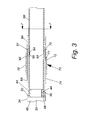
- FIG. 3 is an enlarged fragmentary cross sectioned side view of two pole segments and a lock device.
- FIG. 4 is an enlarged fragmentary perspective view of an end portion of a pole segment illustrating components positioned inside that limit motion.
- FIG. 5 is an enlarged fragmentary perspective view of a motion limiting means and two pole segments.
- FIG. 6 is an enlarged exploded perspective view of a motion limiting means.
- FIG. 7 is a cross sectional view of a lock device taken along line 7 - 7 in FIG. 3 .
- the rake 1 includes a blade 2 and a telescoping pole 3 .
- the pole 3 can be used with other implements such as a saw blade, squeegee and the like.
- the pole 3 includes a plurality of pole segments which are illustrated as four in quantity and are designated 6 A, 6 B, 6 C and 6 D with the pole segments being in telescoping relationship with the segment 6 B being slidably received in segment 6 A and adjacent thereto, the segment 6 C being slidably received in the segment 6 B and adjacent thereto and the segment 6 D being slidably received in segment 6 C and adjacent thereto. See FIG. 2 .
- Any suitable number of segments 6 can be provided in a quantity of two or more as desired.
- the blade 2 can be of any suitable shape and, as shown, has a concave surface 16 from which the pole 3 extends.
- the surface 16 is positioned for normally engaging material such as snow when the blade 2 is moved in a direction that the surface 16 is facing.
- the blade 2 has a compound concave curvature with one curvature being along its length and one curvature being along its height.
- the blade 2 can be provided with reinforcing ribs 18 that extend in a direction generally from a scraping lower edge 19 toward a top edge 20 .
- the ribs 18 are preferably formed as integral parts of the blade 2 .
- the blade 2 is also provided with means for attaching the pole 3 thereto.
- a socket member 22 projects from the surface 16 of the blade 2 and is sized and shaped to receive a proximal (relative to the blade 2 ) end portion 24 of the pole segment 6 D therein.
- the blade 2 can be removably attached to the pole 6 as with a bolt and nut extending through holes in the pole segment 6 D and the socket member 22 or with means such as a snap locking detent allowing push together securement. Such securement secures the blade 2 to the pole segment 6 D in a manner to fix it against both axial and rotational relative movement.
- the blade 2 is of a molded construction using a graphite containing polymer.
- a replaceable wear strip (not shown) can be provided at the lower edge 19 if desired.
- the blade 2 can also be braced to limit flexure during use.
- a pair of lateral brace members 26 function as struts to limit bending of the blade 2 when loaded.
- the braces 26 can be secured at one end thereof to the pole segment 6 D as with a threaded fastener and nut arrangement 27 A, and at the other end to the blade 2 as with a threaded fastener and nut arrangement 27 B.
- the telescoping pole 3 has a plurality of segments 6 (denoted as 6 A, 6 B, 6 C and 6 D for distinction) associated with one another in a manner permitting selective relative longitudinal movement. That is, one segment 6 is movably received within the interior of another segment 6 .
- the segment 6 A is preferably formed of a reinforced polymeric material such as with fiberglass filler and is in the form of a hollow tube.
- the distal end portion 29 (relative to the blade 2 ) can be provided with a handle 31 secured thereto and preferably closing the distal end portion 29 .
- the handle 31 can be provided with an opening 32 or other means to facilitate hanging the rake 1 for storage.
- the segment 6 A has a through passage ( FIG.
- the passage 33 is generally round in transverse cross section.
- the shape of the outer surface 34 is also generally round in transverse cross section.
- the interior pole segments 6 B-D are also preferably similarly generally round in transverse cross section.
- the interior segments 6 B-D are preferably of aluminum tubing and are each sized to fit within its outermost adjacent segment 6 and be axially slidable therein.
- Means is provided for limiting relative axial movement between the pole segments 6 A-D and relative rotation between the pole segments 6 A-D. For relative axial movement, the means keeps the segments from separating and fixes the segments at a selected length of pole 3 .
- the details of pole 3 will be described using segments 6 A and 6 B, but it is to be understood that this description applies to the segments 6 C and 6 D as well.
- the pole segment 6 B has a slide bearing member 49 secured to an end portion 46 of pole segment 6 B as with a snap lock detent 44 extending through an opening 45 .
- the slide 49 includes a sleeve 47 mounted inside the respective end portion 46 of the pole segment 6 B.
- the slide includes a radially extending flange 48 that projects radially beyond the exterior surface 42 B of the segment 6 B and is preferably sized to provide a bearing surface to engage an interior surface 43 A, FIG. 3 , of the adjacent outer segment 6 A.
- the segments 6 B-D each has an exterior surface, 42 B-D respectively.
- the flange 48 has a proximally facing (toward the blade 2 ) surface 50 .
- the pole 3 also includes motion limiting means 59 to positively limit axial movement and separation of one pole segment 6 relative to an immediately adjacent pole segment 6 ; for example, pole segments 6 A and 6 B, which for convenience are used in the following description, as best seen in FIGS. 3-7 .
- a stop member 60 is secured to the pole member 6 B and has a circumferentially and radially outwardly extending shoulder 61 facing the blade or proximal end portion 24 of the pole 3 .
- the stop member 60 is secured to the pole segment 6 B to be immovable relative to the pole segment 6 B.
- the stop member 60 is in the form of a ring portion with a gap 62 between two ends 63 A, 63 B.
- the gap 62 allows for selective expansion and contraction of the diameter of the stop 60 for installation thereof on the pole segment 6 B.
- the stop member 60 is fixed to the pole segment 6 B against longitudinal movement therealong by having a protuberance 64 extend through an opening 65 in the sidewall 66 of the pole segment 6 B. Engagement of an outer surface 67 of the stop member 60 with the interior surface 43 A of the pole segment 6 A retains the stop member secured to the pole segment 6 B by limiting radial expansion of the stop member.
- the stop member 60 is made by molding with a polymeric material such as so called self lubricating nylon. This construction also provides a slide bearing arrangement between the pole segments 6 A, 6 B.
- the means 59 also includes a stop member 70 secured to the pole segment 6 A.
- the securement of the stop member 70 to a respective pole segment 6 is effective to require at least about 80 pounds of axially directed force to separate it from the respective pole segment 6 .
- the stop member 70 includes an interior shoulder 75 facing the shoulder 61 and is operable to selectively engage with the shoulder 61 and positively stop extension and separation of the pole segments 6 A, B to retain them in telescoping relationship. As shown, the stop member 70 has a sleeve portion 76 received over and engaging the proximal end 30 of the pole segment 6 A.
- the stop member 70 is secured to the pole segment 6 A as with a detent 71 extending through an opening 72 through the sidewall 74 of the pole segment 6 A forming a snap lock arrangement to positively secure the stop member 70 to the pole segment 6 A.
- This configuration prevents both axial separation of and relative rotation between the means 59 and its respective pole segment.
- the interior surface 43 A can serve as a bearing surface for movement of the inner positioned pole segment 6 B within the pole segment 6 A riding on the surface 67 of the stop member 60 and also on the outer surface of the flange 48 .
- the means 59 also includes locking means, designated generally as 80 , that is operable to fix adjacent pole segments at a selected extended or retracted position.
- the means 80 can also be configured to key adjacent pole segments 6 to one another to prevent relative rotation therebetween.
- the means 80 includes a clamp mechanism 81 operable to selectively provide both a circumferential force and an inwardly directed radial force on the inner positioned pole segment 6 B.
- a friction locking device 83 extends from the stop member 60 and preferably has portions thereof as an integral part.
- the locking device 83 has a fixed segment 84 with an interior surface shaped and positioned to engage an exterior surface portion 42 B of the immediately adjacent inwardly positioned pole segment 6 B.
- the locking device 83 also includes a tab 85 extending generally circumferentially from the fixed segment 84 and has an edge portion 86 adjacent to an end of the stop member 70 and separated by a gap 87 allowing it to move circumferentially without restraint by the stop member 70 . This permits selective expansion and contraction of the circumference of portions of the locking device 83 .
- a lever clamp member 82 is pivotally associated with ears 88 that are preferably integral with the tab 85 .
- the lever 82 is pivotally connected to a link 94 as with a dowel pin 89 extending through holes through ears 90 of the lever 82 and the link 94 allowing the lever 82 to pivot relative to the ears 88 .
- the lever 82 is provided with a pair of eccentric cam surfaces 91 on the ears 90 that are engageable with a pair of corresponding cam surfaces 92 on the ears 88 .
- the link 94 is also pivotally mounted adjacent one end thereof on a pin 95 to a pair of ears 96 that are positioned on and preferably integral with the fixed segment 84 . There is a gap between the ears 88 , 96 allowing the sets of ears to move relative to one another to allow the gap 97 to expand and contract.
- Pivoting movement of the lever 86 effects movement of the pivot pins 89 , 95 selectively toward and away from one another via action of the cam surfaces 91 on the cam surfaces 92 to open and close the gap and effect selective clamping action of the fixed segment 84 and tab 85 with the pole section 6 B to increase and decrease clamping force thereon and thereby fix the pole segments 6 A, 6 B at a desired extended or retracted position.
- the clamping force when applied via the lever 82 , effects resistance to relative axial movement between the pole segments 6 A, 6 B.
- the clamping force and resulting friction are sufficient to provide a resistance of less than the pole segment separation force discussed above and preferably at least about 50 pounds of axial pulling force to effect relative longitudinal movement between the pole segments 6 A, 6 B.
- pole segments 6 are keyed together to positively resist relative rotation between adjacent sections 6 at least when they are locked against relative axial movement. This allows for potential better control of the blade 2 during use to move snow or the like.
- longitudinally extending ribs and grooves are provided and form a spline connection between adjacent pole segments. This will be described using again pole segments 6 A and 6 B as an example, but the description applies to the other pole segments 6 .
- the exterior surface 42 B of pole segment 6 B is provided with a plurality of generally longitudinally extending alternating ribs 102 and grooves 103 ( FIGS. 4 , 7 ) that are in generally parallel relationship.
- Other shapes of the ribs and grooves may be used if desired.
- the ribs 102 and grooves 103 may be formed when the pole segment 6 B is formed as by extrusion using a metal alloy such as aluminum alloy, and as shown extend along at least substantially the entire length of the pole segment.
- the locking means 80 and as shown, the clamp mechanism 81 is also provided with corresponding ribs 105 and grooves 106 for receiving and interengaging the grooves 103 and ribs 102 respectively in a manner that allows relative longitudinal movement of the pole segments 6 A, B 6 , and when the clamp mechanism 81 is in an unlatched position will positively prevent relative rotation of the pole segments 6 A, 6 B when in a latched condition.
- the ribs 105 and grooves 106 are in the interior surface 110 of preferably both of the fixed segment 84 and tab 85 of the clamp mechanism 81 .
- a rake 1 can be shipped with the blade 2 not assembled to the pole 3 .
- the user can easily adjust the length of pole 3 and lock the segments 6 at the desired length using the locking means 80 as described above.
- the blade 2 can then be positioned on a surface such as a snow covered roof, and with a pulling motion move the blade and material to be moved toward the user.
Landscapes
- Engineering & Computer Science (AREA)
- Architecture (AREA)
- Civil Engineering (AREA)
- Structural Engineering (AREA)
- Mechanical Engineering (AREA)
- Buildings Adapted To Withstand Abnormal External Influences (AREA)
Abstract
Description
Claims (6)
Priority Applications (2)
| Application Number | Priority Date | Filing Date | Title |
|---|---|---|---|
| US13/761,967 US9120217B2 (en) | 2013-02-07 | 2013-02-07 | Snow rake with telescoping pole |
| CA2841702A CA2841702C (en) | 2013-02-07 | 2014-02-05 | Snow rake with telescoping pole |
Applications Claiming Priority (1)
| Application Number | Priority Date | Filing Date | Title |
|---|---|---|---|
| US13/761,967 US9120217B2 (en) | 2013-02-07 | 2013-02-07 | Snow rake with telescoping pole |
Publications (2)
| Publication Number | Publication Date |
|---|---|
| US20140215864A1 US20140215864A1 (en) | 2014-08-07 |
| US9120217B2 true US9120217B2 (en) | 2015-09-01 |
Family
ID=51258018
Family Applications (1)
| Application Number | Title | Priority Date | Filing Date |
|---|---|---|---|
| US13/761,967 Active 2033-11-25 US9120217B2 (en) | 2013-02-07 | 2013-02-07 | Snow rake with telescoping pole |
Country Status (2)
| Country | Link |
|---|---|
| US (1) | US9120217B2 (en) |
| CA (1) | CA2841702C (en) |
Cited By (10)
| Publication number | Priority date | Publication date | Assignee | Title |
|---|---|---|---|---|
| US9587359B1 (en) * | 2016-06-07 | 2017-03-07 | Lilun Plastics Enterprise Co Ltd. | Snow removal apparatus |
| US9981707B1 (en) * | 2017-11-14 | 2018-05-29 | Kalloy Industrial Co., Ltd. | Anti-theft device for bicycle seat post |
| US10767371B1 (en) | 2018-09-13 | 2020-09-08 | Mark C. Ramsey | Snow rake |
| US10794060B1 (en) * | 2018-09-13 | 2020-10-06 | Mark C. Ramsey | Snow rake |
| USD897793S1 (en) | 2019-07-19 | 2020-10-06 | Mark C. Ramsey | Snow rake |
| US11225764B2 (en) * | 2019-01-14 | 2022-01-18 | Joseph Wyatt | Combination snow shovel and roof rake |
| US11346473B2 (en) * | 2018-09-04 | 2022-05-31 | Chien-Ting Lin | Sleeve |
| USD1017353S1 (en) * | 2022-06-23 | 2024-03-12 | Wuyi Chaoyang Plastic Co., Ltd | Ice scraper |
| US20250035141A1 (en) * | 2023-07-25 | 2025-01-30 | James R. Conrad | Telescoping apparatus |
| US20250170698A1 (en) * | 2023-11-23 | 2025-05-29 | Garant Gp | Hand tools and method of fabrication thereof |
Families Citing this family (29)
| Publication number | Priority date | Publication date | Assignee | Title |
|---|---|---|---|---|
| US8568015B2 (en) | 2010-09-23 | 2013-10-29 | Willis Electric Co., Ltd. | Decorative light string for artificial lighted tree |
| US8298633B1 (en) | 2011-05-20 | 2012-10-30 | Willis Electric Co., Ltd. | Multi-positional, locking artificial tree trunk |
| US8863416B2 (en) | 2011-10-28 | 2014-10-21 | Polygroup Macau Limited (Bvi) | Powered tree construction |
| US9157587B2 (en) | 2011-11-14 | 2015-10-13 | Willis Electric Co., Ltd. | Conformal power adapter for lighted artificial tree |
| US8569960B2 (en) | 2011-11-14 | 2013-10-29 | Willis Electric Co., Ltd | Conformal power adapter for lighted artificial tree |
| US8876321B2 (en) | 2011-12-09 | 2014-11-04 | Willis Electric Co., Ltd. | Modular lighted artificial tree |
| US9179793B2 (en) | 2012-05-08 | 2015-11-10 | Willis Electric Co., Ltd. | Modular tree with rotation-lock electrical connectors |
| US9044056B2 (en) | 2012-05-08 | 2015-06-02 | Willis Electric Co., Ltd. | Modular tree with electrical connector |
| US9572446B2 (en) | 2012-05-08 | 2017-02-21 | Willis Electric Co., Ltd. | Modular tree with locking trunk and locking electrical connectors |
| US10206530B2 (en) | 2012-05-08 | 2019-02-19 | Willis Electric Co., Ltd. | Modular tree with locking trunk |
| US20170282348A1 (en) * | 2012-12-27 | 2017-10-05 | Moshe Mark | Multipurpose cleaning tool having an interchangable head |
| US9671074B2 (en) | 2013-03-13 | 2017-06-06 | Willis Electric Co., Ltd. | Modular tree with trunk connectors |
| US9439528B2 (en) | 2013-03-13 | 2016-09-13 | Willis Electric Co., Ltd. | Modular tree with locking trunk and locking electrical connectors |
| US9894949B1 (en) | 2013-11-27 | 2018-02-20 | Willis Electric Co., Ltd. | Lighted artificial tree with improved electrical connections |
| US8870404B1 (en) | 2013-12-03 | 2014-10-28 | Willis Electric Co., Ltd. | Dual-voltage lighted artificial tree |
| US9883566B1 (en) | 2014-05-01 | 2018-01-30 | Willis Electric Co., Ltd. | Control of modular lighted artificial trees |
| US9839315B2 (en) | 2015-03-27 | 2017-12-12 | Polygroup Macau Limited (Bvi) | Multi-wire quick assemble tree |
| WO2016196763A1 (en) | 2015-06-02 | 2016-12-08 | DMOS Collective, Inc. | Device, system, and method for shoveling and shaping snow |
| US9907136B2 (en) | 2016-03-04 | 2018-02-27 | Polygroup Macau Limited (Bv) | Variable multi-color LED light string and controller for an artificial tree |
| US9960558B2 (en) * | 2016-03-04 | 2018-05-01 | Polygroup Macau Limited (Bvi) | Powered tree construction |
| USD811181S1 (en) | 2016-12-12 | 2018-02-27 | DMOS Collective, Inc. | Shovel |
| US10441014B1 (en) | 2017-01-03 | 2019-10-15 | Willis Electric Co., Ltd. | Artificial tree having multiple tree portions with electrical connectors secured therein |
| US10683974B1 (en) | 2017-12-11 | 2020-06-16 | Willis Electric Co., Ltd. | Decorative lighting control |
| EP3812089A1 (en) | 2019-10-23 | 2021-04-28 | Black & Decker Inc. | Pole sander |
| GB201915324D0 (en) * | 2019-10-23 | 2019-12-04 | Black & Decker Inc | Pole sander |
| EP3812090B8 (en) | 2019-10-23 | 2025-09-10 | Black & Decker Inc. | Pole sander |
| EP3812091B1 (en) | 2019-10-23 | 2023-05-10 | Black & Decker Inc. | Pole sander |
| EP4063068B1 (en) | 2019-10-23 | 2026-02-18 | Black & Decker, Inc. | Pole sander |
| US11867224B2 (en) | 2021-01-27 | 2024-01-09 | Black & Decker Inc. | Locking mechanism for two telescoping poles of a power tool |
Citations (20)
| Publication number | Priority date | Publication date | Assignee | Title |
|---|---|---|---|---|
| US3091790A (en) * | 1962-06-01 | 1963-06-04 | Lester A Schroeder | Snow and ice removal tool |
| US3583747A (en) * | 1969-04-24 | 1971-06-08 | Agard L Lambert | Snow removing apparatus |
| US3751748A (en) * | 1971-12-15 | 1973-08-14 | Wooster Beush Co | Hand held roller frame |
| US4325157A (en) * | 1979-08-09 | 1982-04-20 | E Z Painter Corporation | Extension handle |
| US4848819A (en) | 1988-08-26 | 1989-07-18 | Moorefield Frank R | Snow rake |
| US4947562A (en) * | 1989-01-25 | 1990-08-14 | Williamson James W | Self-loading snow removal tool |
| US5067197A (en) | 1990-09-26 | 1991-11-26 | Cormier Frederick P | Snow rake |
| USD329004S (en) | 1990-08-24 | 1992-09-01 | Causby King | Snow moving blade attachment for a yard rake |
| USD345492S (en) | 1993-04-02 | 1994-03-29 | Mele Peter C | Roof snow rake |
| US5524369A (en) * | 1994-10-04 | 1996-06-11 | Phillips; Kent D. | Snow removal device |
| USD384558S (en) | 1995-12-29 | 1997-10-07 | Mele Peter C | Combined roof snow rake and pusher |
| US5676413A (en) | 1996-04-29 | 1997-10-14 | Garelick Mfg. Co. | Roof snow rake blade |
| USD391815S (en) | 1997-02-10 | 1998-03-10 | William Venezio | Roof snow rake |
| USD405666S (en) | 1998-01-29 | 1999-02-16 | Suncast Corporation | Snow roof rake |
| US5887364A (en) | 1996-12-04 | 1999-03-30 | Toth; Julius A. | Snow removal attachment for a rake |
| USD414389S (en) | 1997-01-27 | 1999-09-28 | Mele Peter C | Combined roof rake and snow pusher |
| US6142699A (en) * | 1998-04-21 | 2000-11-07 | Asia Link Co., Ltd. | Telescopic rod |
| US6189942B1 (en) | 1999-02-08 | 2001-02-20 | Francis Peterson | Snow rake |
| USD539496S1 (en) | 2004-09-20 | 2007-03-27 | Hopkins Manufacturing Corporation | Extendable snow rake |
| US8347528B1 (en) * | 2010-10-20 | 2013-01-08 | Seltzer Richard E | Surface rake apparatus |
-
2013
- 2013-02-07 US US13/761,967 patent/US9120217B2/en active Active
-
2014
- 2014-02-05 CA CA2841702A patent/CA2841702C/en active Active
Patent Citations (20)
| Publication number | Priority date | Publication date | Assignee | Title |
|---|---|---|---|---|
| US3091790A (en) * | 1962-06-01 | 1963-06-04 | Lester A Schroeder | Snow and ice removal tool |
| US3583747A (en) * | 1969-04-24 | 1971-06-08 | Agard L Lambert | Snow removing apparatus |
| US3751748A (en) * | 1971-12-15 | 1973-08-14 | Wooster Beush Co | Hand held roller frame |
| US4325157A (en) * | 1979-08-09 | 1982-04-20 | E Z Painter Corporation | Extension handle |
| US4848819A (en) | 1988-08-26 | 1989-07-18 | Moorefield Frank R | Snow rake |
| US4947562A (en) * | 1989-01-25 | 1990-08-14 | Williamson James W | Self-loading snow removal tool |
| USD329004S (en) | 1990-08-24 | 1992-09-01 | Causby King | Snow moving blade attachment for a yard rake |
| US5067197A (en) | 1990-09-26 | 1991-11-26 | Cormier Frederick P | Snow rake |
| USD345492S (en) | 1993-04-02 | 1994-03-29 | Mele Peter C | Roof snow rake |
| US5524369A (en) * | 1994-10-04 | 1996-06-11 | Phillips; Kent D. | Snow removal device |
| USD384558S (en) | 1995-12-29 | 1997-10-07 | Mele Peter C | Combined roof snow rake and pusher |
| US5676413A (en) | 1996-04-29 | 1997-10-14 | Garelick Mfg. Co. | Roof snow rake blade |
| US5887364A (en) | 1996-12-04 | 1999-03-30 | Toth; Julius A. | Snow removal attachment for a rake |
| USD414389S (en) | 1997-01-27 | 1999-09-28 | Mele Peter C | Combined roof rake and snow pusher |
| USD391815S (en) | 1997-02-10 | 1998-03-10 | William Venezio | Roof snow rake |
| USD405666S (en) | 1998-01-29 | 1999-02-16 | Suncast Corporation | Snow roof rake |
| US6142699A (en) * | 1998-04-21 | 2000-11-07 | Asia Link Co., Ltd. | Telescopic rod |
| US6189942B1 (en) | 1999-02-08 | 2001-02-20 | Francis Peterson | Snow rake |
| USD539496S1 (en) | 2004-09-20 | 2007-03-27 | Hopkins Manufacturing Corporation | Extendable snow rake |
| US8347528B1 (en) * | 2010-10-20 | 2013-01-08 | Seltzer Richard E | Surface rake apparatus |
Cited By (11)
| Publication number | Priority date | Publication date | Assignee | Title |
|---|---|---|---|---|
| US9587359B1 (en) * | 2016-06-07 | 2017-03-07 | Lilun Plastics Enterprise Co Ltd. | Snow removal apparatus |
| US9981707B1 (en) * | 2017-11-14 | 2018-05-29 | Kalloy Industrial Co., Ltd. | Anti-theft device for bicycle seat post |
| US11346473B2 (en) * | 2018-09-04 | 2022-05-31 | Chien-Ting Lin | Sleeve |
| US10767371B1 (en) | 2018-09-13 | 2020-09-08 | Mark C. Ramsey | Snow rake |
| US10794060B1 (en) * | 2018-09-13 | 2020-10-06 | Mark C. Ramsey | Snow rake |
| US11066831B2 (en) * | 2018-09-13 | 2021-07-20 | Mark C. Ramsey | Snow rake |
| US11225764B2 (en) * | 2019-01-14 | 2022-01-18 | Joseph Wyatt | Combination snow shovel and roof rake |
| USD897793S1 (en) | 2019-07-19 | 2020-10-06 | Mark C. Ramsey | Snow rake |
| USD1017353S1 (en) * | 2022-06-23 | 2024-03-12 | Wuyi Chaoyang Plastic Co., Ltd | Ice scraper |
| US20250035141A1 (en) * | 2023-07-25 | 2025-01-30 | James R. Conrad | Telescoping apparatus |
| US20250170698A1 (en) * | 2023-11-23 | 2025-05-29 | Garant Gp | Hand tools and method of fabrication thereof |
Also Published As
| Publication number | Publication date |
|---|---|
| CA2841702A1 (en) | 2014-08-07 |
| CA2841702C (en) | 2020-06-09 |
| US20140215864A1 (en) | 2014-08-07 |
Similar Documents
| Publication | Publication Date | Title |
|---|---|---|
| US9120217B2 (en) | Snow rake with telescoping pole | |
| US9651073B2 (en) | Locking mechanism for telescoping members | |
| US7111574B2 (en) | Telescoping outrigger boom with tube locking mechanisms | |
| CN107427111A (en) | Umbrella with anti-reflective rotary device | |
| US8851784B2 (en) | System of an extension pole | |
| AU2009202854B2 (en) | Coupling Device | |
| US20150202766A1 (en) | Non-Rotatable Telescopic Handle Construction | |
| RU2016143414A (en) | FOLDING STICK WITH TUBULAR COUPLING | |
| US20140194212A1 (en) | Expandable Baton With Locking Mechanism | |
| EP1712297A1 (en) | Locking mechanism for an extension pole | |
| US20180363800A1 (en) | Locking/ indexing pin | |
| JP5658950B2 (en) | Folding cane | |
| US7661473B2 (en) | Expansion enhancement device | |
| US10508765B2 (en) | Extendible tripod leg | |
| FI119888B (en) | Socket joint between outer tube and inner tube of shaft telescopically adjustable with respect to its length | |
| CN117967890A (en) | One-key locking telescopic tube and tripod | |
| CN110410391B (en) | Locking buckle, telescopic tube group, tripod and self-timer rod | |
| US9719577B2 (en) | Mechanical rope wedge | |
| JP3187349U (en) | Snow remover | |
| EP1949812B1 (en) | Positioning sleeve for a telescopic rod | |
| US9103409B2 (en) | Readily releasable wedge assembly for holding a wire rope in a socket | |
| US1018941A (en) | Collapsible umbrella. | |
| US12250935B2 (en) | Telescoping outrigger arm | |
| AU2004200242B2 (en) | Spiral cam-lock system | |
| EP4424952A1 (en) | A joint |
Legal Events
| Date | Code | Title | Description |
|---|---|---|---|
| AS | Assignment |
Owner name: SUNCAST TECHNOLOGIES, LLC, FLORIDA Free format text: ASSIGNMENT OF ASSIGNORS INTEREST;ASSIGNORS:FISCHER, GARY M., JR.;VOGLER, MICHAEL R.;REEL/FRAME:031274/0352 Effective date: 20130517 |
|
| STCF | Information on status: patent grant |
Free format text: PATENTED CASE |
|
| MAFP | Maintenance fee payment |
Free format text: PAYMENT OF MAINTENANCE FEE, 4TH YEAR, LARGE ENTITY (ORIGINAL EVENT CODE: M1551); ENTITY STATUS OF PATENT OWNER: LARGE ENTITY Year of fee payment: 4 |
|
| AS | Assignment |
Owner name: JPMORGAN CHASE BANK, N.A., AS ADMINISTRATIVE AGENT Free format text: SECURITY INTEREST;ASSIGNOR:SUNCAST TECHNOLOGIES, LLC;REEL/FRAME:048840/0588 Effective date: 20190408 Owner name: JPMORGAN CHASE BANK, N.A., AS ADMINISTRATIVE AGENT, ILLINOIS Free format text: SECURITY INTEREST;ASSIGNOR:SUNCAST TECHNOLOGIES, LLC;REEL/FRAME:048840/0588 Effective date: 20190408 |
|
| MAFP | Maintenance fee payment |
Free format text: PAYMENT OF MAINTENANCE FEE, 8TH YEAR, LARGE ENTITY (ORIGINAL EVENT CODE: M1552); ENTITY STATUS OF PATENT OWNER: LARGE ENTITY Year of fee payment: 8 |