US9112573B2 - Method and apparatus for coding a signal in a relay network - Google Patents
Method and apparatus for coding a signal in a relay network Download PDFInfo
- Publication number
- US9112573B2 US9112573B2 US13/874,580 US201313874580A US9112573B2 US 9112573 B2 US9112573 B2 US 9112573B2 US 201313874580 A US201313874580 A US 201313874580A US 9112573 B2 US9112573 B2 US 9112573B2
- Authority
- US
- United States
- Prior art keywords
- encoding
- precoding
- node
- antenna
- relay
- Prior art date
- Legal status (The legal status is an assumption and is not a legal conclusion. Google has not performed a legal analysis and makes no representation as to the accuracy of the status listed.)
- Active, expires
Links
- 238000000034 method Methods 0.000 title claims description 21
- 238000004891 communication Methods 0.000 claims abstract description 13
- 230000000694 effects Effects 0.000 claims abstract description 5
- 125000004122 cyclic group Chemical group 0.000 claims description 21
- 230000001131 transforming effect Effects 0.000 claims 1
- 230000005540 biological transmission Effects 0.000 abstract description 3
- 239000011159 matrix material Substances 0.000 description 35
- 238000013461 design Methods 0.000 description 23
- 230000008901 benefit Effects 0.000 description 5
- 238000007476 Maximum Likelihood Methods 0.000 description 3
- 238000012545 processing Methods 0.000 description 3
- 230000000052 comparative effect Effects 0.000 description 2
- 238000001514 detection method Methods 0.000 description 2
- 238000005562 fading Methods 0.000 description 2
- 230000003321 amplification Effects 0.000 description 1
- 238000013459 approach Methods 0.000 description 1
- 238000004883 computer application Methods 0.000 description 1
- 238000004590 computer program Methods 0.000 description 1
- 230000001934 delay Effects 0.000 description 1
- 238000009795 derivation Methods 0.000 description 1
- 238000011161 development Methods 0.000 description 1
- 238000005516 engineering process Methods 0.000 description 1
- 238000009472 formulation Methods 0.000 description 1
- 239000000203 mixture Substances 0.000 description 1
- 238000012986 modification Methods 0.000 description 1
- 230000004048 modification Effects 0.000 description 1
- 238000003199 nucleic acid amplification method Methods 0.000 description 1
- 238000004088 simulation Methods 0.000 description 1
- 238000006467 substitution reaction Methods 0.000 description 1
- 239000013589 supplement Substances 0.000 description 1
Images


Classifications
-
- H—ELECTRICITY
- H04—ELECTRIC COMMUNICATION TECHNIQUE
- H04B—TRANSMISSION
- H04B7/00—Radio transmission systems, i.e. using radiation field
- H04B7/02—Diversity systems; Multi-antenna system, i.e. transmission or reception using multiple antennas
- H04B7/04—Diversity systems; Multi-antenna system, i.e. transmission or reception using multiple antennas using two or more spaced independent antennas
- H04B7/0413—MIMO systems
-
- H—ELECTRICITY
- H04—ELECTRIC COMMUNICATION TECHNIQUE
- H04B—TRANSMISSION
- H04B7/00—Radio transmission systems, i.e. using radiation field
- H04B7/14—Relay systems
- H04B7/15—Active relay systems
-
- H—ELECTRICITY
- H04—ELECTRIC COMMUNICATION TECHNIQUE
- H04B—TRANSMISSION
- H04B7/00—Radio transmission systems, i.e. using radiation field
- H04B7/02—Diversity systems; Multi-antenna system, i.e. transmission or reception using multiple antennas
- H04B7/022—Site diversity; Macro-diversity
- H04B7/026—Co-operative diversity, e.g. using fixed or mobile stations as relays
-
- H—ELECTRICITY
- H04—ELECTRIC COMMUNICATION TECHNIQUE
- H04B—TRANSMISSION
- H04B7/00—Radio transmission systems, i.e. using radiation field
- H04B7/02—Diversity systems; Multi-antenna system, i.e. transmission or reception using multiple antennas
- H04B7/04—Diversity systems; Multi-antenna system, i.e. transmission or reception using multiple antennas using two or more spaced independent antennas
- H04B7/06—Diversity systems; Multi-antenna system, i.e. transmission or reception using multiple antennas using two or more spaced independent antennas at the transmitting station
- H04B7/0613—Diversity systems; Multi-antenna system, i.e. transmission or reception using multiple antennas using two or more spaced independent antennas at the transmitting station using simultaneous transmission
- H04B7/0667—Diversity systems; Multi-antenna system, i.e. transmission or reception using multiple antennas using two or more spaced independent antennas at the transmitting station using simultaneous transmission of delayed versions of same signal
- H04B7/0669—Diversity systems; Multi-antenna system, i.e. transmission or reception using multiple antennas using two or more spaced independent antennas at the transmitting station using simultaneous transmission of delayed versions of same signal using different channel coding between antennas
-
- H—ELECTRICITY
- H04—ELECTRIC COMMUNICATION TECHNIQUE
- H04L—TRANSMISSION OF DIGITAL INFORMATION, e.g. TELEGRAPHIC COMMUNICATION
- H04L1/00—Arrangements for detecting or preventing errors in the information received
- H04L1/004—Arrangements for detecting or preventing errors in the information received by using forward error control
- H04L1/0076—Distributed coding, e.g. network coding, involving channel coding
- H04L1/0077—Cooperative coding
-
- H—ELECTRICITY
- H04—ELECTRIC COMMUNICATION TECHNIQUE
- H04L—TRANSMISSION OF DIGITAL INFORMATION, e.g. TELEGRAPHIC COMMUNICATION
- H04L1/00—Arrangements for detecting or preventing errors in the information received
- H04L1/02—Arrangements for detecting or preventing errors in the information received by diversity reception
- H04L1/06—Arrangements for detecting or preventing errors in the information received by diversity reception using space diversity
- H04L1/0618—Space-time coding
- H04L1/0637—Properties of the code
- H04L1/0643—Properties of the code block codes
-
- H—ELECTRICITY
- H04—ELECTRIC COMMUNICATION TECHNIQUE
- H04L—TRANSMISSION OF DIGITAL INFORMATION, e.g. TELEGRAPHIC COMMUNICATION
- H04L1/00—Arrangements for detecting or preventing errors in the information received
- H04L1/02—Arrangements for detecting or preventing errors in the information received by diversity reception
- H04L1/06—Arrangements for detecting or preventing errors in the information received by diversity reception using space diversity
- H04L1/0618—Space-time coding
- H04L1/0637—Properties of the code
- H04L1/0662—Limited orthogonality systems
-
- H—ELECTRICITY
- H04—ELECTRIC COMMUNICATION TECHNIQUE
- H04L—TRANSMISSION OF DIGITAL INFORMATION, e.g. TELEGRAPHIC COMMUNICATION
- H04L1/00—Arrangements for detecting or preventing errors in the information received
- H04L1/02—Arrangements for detecting or preventing errors in the information received by diversity reception
- H04L1/06—Arrangements for detecting or preventing errors in the information received by diversity reception using space diversity
- H04L1/0618—Space-time coding
- H04L1/0637—Properties of the code
- H04L1/0668—Orthogonal systems, e.g. using Alamouti codes
-
- H—ELECTRICITY
- H04—ELECTRIC COMMUNICATION TECHNIQUE
- H04B—TRANSMISSION
- H04B7/00—Radio transmission systems, i.e. using radiation field
- H04B7/02—Diversity systems; Multi-antenna system, i.e. transmission or reception using multiple antennas
- H04B7/04—Diversity systems; Multi-antenna system, i.e. transmission or reception using multiple antennas using two or more spaced independent antennas
- H04B7/06—Diversity systems; Multi-antenna system, i.e. transmission or reception using multiple antennas using two or more spaced independent antennas at the transmitting station
- H04B7/0613—Diversity systems; Multi-antenna system, i.e. transmission or reception using multiple antennas using two or more spaced independent antennas at the transmitting station using simultaneous transmission
- H04B7/0667—Diversity systems; Multi-antenna system, i.e. transmission or reception using multiple antennas using two or more spaced independent antennas at the transmitting station using simultaneous transmission of delayed versions of same signal
- H04B7/0671—Diversity systems; Multi-antenna system, i.e. transmission or reception using multiple antennas using two or more spaced independent antennas at the transmitting station using simultaneous transmission of delayed versions of same signal using different delays between antennas
-
- H—ELECTRICITY
- H04—ELECTRIC COMMUNICATION TECHNIQUE
- H04B—TRANSMISSION
- H04B7/00—Radio transmission systems, i.e. using radiation field
- H04B7/24—Radio transmission systems, i.e. using radiation field for communication between two or more posts
- H04B7/26—Radio transmission systems, i.e. using radiation field for communication between two or more posts at least one of which is mobile
- H04B7/2603—Arrangements for wireless physical layer control
- H04B7/2606—Arrangements for base station coverage control, e.g. by using relays in tunnels
-
- H—ELECTRICITY
- H04—ELECTRIC COMMUNICATION TECHNIQUE
- H04L—TRANSMISSION OF DIGITAL INFORMATION, e.g. TELEGRAPHIC COMMUNICATION
- H04L1/00—Arrangements for detecting or preventing errors in the information received
- H04L2001/0092—Error control systems characterised by the topology of the transmission link
- H04L2001/0097—Relays
Definitions
- Embodiments described herein relate to relaying of MIMO communications, and particularly to the coding of signals within such communications.
- MIMO multiple input, multiple output
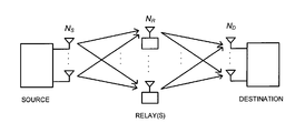
- FIG. 1 illustrates a customary dual-hop communications network in the field of the disclosure
- FIG. 2 a illustrates the network of FIG. 1 configured for OSTBC encoding at the source
- FIG. 2 b illustrates the network of FIG. 1 configured for homogeneous OSTBC encoding at the source and distributed OSTBC precoding at the relay;
- FIG. 3 a illustrates the network of FIG. 1 configured, in accordance with a first embodiment, for heterogeneous encoding and precoding at the source and relay respectively;
- FIG. 3 b illustrates the network of FIG. 1 configured, in accordance with a first embodiment, for heterogeneous encoding and precoding at the source and relay respectively;
- FIG. 4 illustrates an implementation of the first embodiment, with a single antenna destination node
- FIG. 5 illustrates a graph of bit-error rates for comparative examples of implementations of the configurations shown in FIGS. 2 a , 2 b , 3 a and 3 b;
- FIG. 6 illustrates a graph of bit-error rates for comparative examples of further implementations of the configurations shown in FIGS. 2 a , 2 b , 3 a and 3 b;
- FIG. 7 illustrates a schematic architecture of a source node of the configurations shown in FIG. 3 a or 3 b ;
- FIG. 8 illustrates a schematic architecture of a relay node of the configurations shown in FIG. 3 a or 3 b.
- An embodiment described herein provides a method of transmitting a signal from a multi-antenna source node, via a multi-antenna relay node, to a multi-antenna destination node, the method comprising applying an encoding at the source node, and applying a precoding at the relay node, the encoding and precoding being heterogeneous, and the encoding and precoding being, in combination, a quasi-orthogonal space time block coding.
- One of the encoding and the precoding may comprise a first space time coding which is quasi-orthogonal.
- the other of the encoding and the precoding may comprise a second space time coding which is a delay-and-forward coding.
- the second space time coding may comprise a group cyclic delay code.
- the source node may comprise two antennas, wherein the encoding applied at the source node comprises an Alamouti encoding, and the precoding at the relay node comprises a group cyclic delay code.
- the source node may comprise more than two antennas, wherein the encoding applied at the source node comprises a quasi-orthogonal space time block code and the precoding applied at the relay node comprises a group cyclic delay code.
- the encoder may comprise a block diagonal matrix relationship between unencoded information and encoded information, the block diagonal matrix relationship being constructed from a series of instances of a first square matrix and a series of instances of a second square matrix.
- the second matrix may be the transpose of the first matrix.
- the block diagonal matrix relationship may be defined such that it applies a different coding at each antenna.
- the first square matrix and the second square matrix may each define cyclic delay codes.
- Another embodiment described herein provides a communications network comprising a multi-antenna source node, a multi-antenna relay node, and a multi-antenna destination node, the source node being operable to transmit a signal via the relay node to the destination node, the source node comprising an encoder for applying an encoding to the signal, and the relay node comprising a precoder for applying a precoding at the relay node, the encoding and precoding being heterogeneous, and the net effect of the encoding and precoding being to apply a quasi-orthogonal space time block coding to the signal.
- FIG. 1 illustrates a dual-hop N S ⁇ N R ⁇ N D MIMO relay network, where N S , N R and N D denote the number of source, relay and destination antennas.
- N S , N R and N D denote the number of source, relay and destination antennas.
- FIG. 1 depicts N R single-antenna relays instead of a single relay node with N R co-located antennas. This depiction can be provided because, in the described embodiment, joint signal processing between relay antennas is not required. Therefore, as will be appreciated by the reader, in light of this, there is no operational difference between described embodiments employing N R spatially distributed single-antenna relays and an embodiment employing a single relay node with N R co-located antennas.
- FIG. 2( a ) illustrates the straight-AF scheme, wherein each relay antenna simply amplifies and forwards its received signal with a fixed gain.
- OSTBC orthogonal space time block coding
- FIG. 2( b ) shows another relaying scheme for dual-hop MIMO-STBC AF relay networks, known as the cascaded-OSTBC scheme.
- OSTBC encoding is performed at the source and distributed OSTBC precoding is performed at the relays.
- the OSTBC at the source and the distributed OSTBC at the relays are homogeneous.
- the OSTBC encoding scheme at the source and the distributed OSTBC precoding scheme at the relays need to be designed jointly in order to construct a specific OSTBC in a cascaded and distributed manner.
- a distributed CDD scheme can be employed in a dual-hop 1 ⁇ N R ⁇ 1 AF relay network, where each relay amplifies and forwards a random cyclic delay version of its received signal. As seen by the destination node, this creates an artificial time-dispersive channel (or frequency-selective fading channel).
- Using this distributed CDD scheme improves diversity gain at the cost of increasing the frequency-selectivity of the equivalent channel (which results in an artificial ISI).
- a linear frequency domain equalizer FDE
- alternative equalizers can be used in place of the linear FDE, such as decision feedback equalizers and linear time domain equalizers.
- the transmit signal from a source antenna passes through all relay antennas and is added up at each destination antenna in a non-orthogonal manner. This leads to a loss in diversity and/or coding gain.
- the encoder at the source and the distributed precoder at the relays are homogeneous OSTBC. This means that the encoder and distributed precoder have to be designed jointly in order to construct a specific OSTBC in a cascaded and distributed manner.
- cascaded-OSTBC scheme cannot be extended to a generalized dual-hop MIMO AF relay network with arbitrary numbers of source and relay antennas.
- Embodiments presented herein use a generalized quasi-orthogonal space-time relaying code (QSTRC) design, where the encoder at the source and the precoder at the relays can be heterogeneous (i.e. two different types of space-time codes).
- QSTRC quasi-orthogonal space-time relaying code
- Embodiments described herein set forth a heterogeneous encoder (at the source) and a distributed precoder (at the relay). As long as the encoder and distributed precoder design can be generalized, cascading a heterogeneous encoder and a distributed precoder leads to a new class of flexible (rather than specific) complex QSTRC that can also be generalized in a dual-hop MIMO-STBC AF relay network with arbitrary N S and N R .
- An embodiment described herein provides a practical example of QSTRC design—namely a delay-and-forward (DLF) scheme, where the source uses OSTBC as its encoder and the relays use group cyclic delay codes (CDC) as distributed precoders (which will be referred to below as the DLF-I scheme).
- the group CDC can be used at the source and distributed OSTBC can be used at the relays, which will be referred to as the DLF-II scheme.
- the distributed CDD scheme described above is employed in a specific 1 ⁇ N R ⁇ 1 dual-hop MIMO relay network.
- a block-based CDC with a random cyclic delay is used as a precoder matrix at each relay to achieve cooperative diversity gain via creating an artificial frequency selective fading channel seen by the destination.
- the destination then uses a linear FDE to recover the data symbols.
- a distributed CDD scheme can benefit from a performance gain due to diversity improvement, it can also suffer from a performance loss due to the residual-ISI resulted from non-ideal equalization.
- Embodiments described herein therefore present a sub-block based CDC as the distributed precoder matrix, wherein each sub-block may have different cyclic delays for the same relay.
- the purpose of using such a distributed precoder matrix at the relays is to construct a new class of flexible QSTRC seen by the destination, and the destination can then use maximum-likelihood detection (MLD) to decode the data symbols.
- MLD maximum-likelihood detection
- the DLF technique described below improves the coding gain while yielding an excellent diversity gain.
- An embodiment provides a method of designing generalized quasi-orthogonal space-time relaying codes (QSTRC) for dual-hop N ⁇ M ⁇ N D MIMO-STBC AF relay networks that can be generalized to arbitrary numbers of source, relay and destination antennas (denoted as N, M and N D respectively).
- QSTRC quasi-orthogonal space-time relaying codes
- the encoder design at the source and the distributed precoder design at the relays may be heterogeneous in the sense that the encoding scheme at the source and the precoding scheme at the relays may use two different types of codes.
- OSTBC space-time block codes
- K ⁇ M/2, and the sub-matrices A i and B i are both N ⁇ N square matrices.
- P i may be different at each relay or source antenna, i.e. A i ⁇ A m (B i ⁇ B m ) for i ⁇ m.
- J i (J ⁇ i ) is a square circulant matrix obtained by cyclically shifting an identity matrix I down (up) by i elements.
- the application of QSTRC design may be extended to three-hop 1 ⁇ N ⁇ M ⁇ N D MIMO-STBC AF relay networks.
- QSTRC design may be extended to dual-hop MIMO-STBC AF relay networks using two-way relaying communications.
- QSTRC design may be employed in conventional single-hop MIMO-STBC systems.
- FIG. 3( a ) and FIG. 3( b ) show a GPF-I scheme.
- GPF-I scheme an OSTBC encoder at the source and a generalized distributed precoder (which can be orthogonal or non-orthogonal) at the relays are heterogeneous codes such that a flexible QSTBC (seen at the destination) can be constructed in a cascaded and distributed manner. Therefore, the GPF scheme is well-suited for a dual-hop MIMO-STBC AF relay networks and can be extended to an arbitrary number of source and relay antennas.
- FIG. 3( b ) shows a GPF-II scheme with a generalized encoder at the source and distributed OSTBC precoder at the relays.
- the reader will appreciate that the GPF-II scheme can be derived from the GPF-I scheme using the same concept of heterogeneous source encoder design and relay precoder design. Hence, the remainder of this disclosure focuses on providing a description of the GPF-I scheme.
- N S N
- N R M
- N D 1 respectively.
- an OSTBC matrix used at the N-antenna source is a 2K ⁇ N matrix (K ⁇ N) and it can be expressed as
- n i is the received noise vector at the i-th relay.
- P i denotes a generalized distributed precoder matrix used at the at the i-th relay and ⁇ denotes a fixed or variable amplification gain; the transmit signal at the i-th relay is
- the destination can decode the data symbols transmitted from the source using the corresponding STBC decoder for the space-time relaying code matrix C.
- C is an OSTBC
- a simple linear combining STBC decoder can be used at the destination.
- C is a QSTBC
- maximum-likelihood detection (MLD) can be used as the STBC decoder at the destination.
- a flexible quasi-orthogonal STRC (QSTRC) design is employed for dual-hop MIMO-STBC AF relay networks.
- This embodiment employs a heterogeneous encoder design x j and distributed precoder design P i in the sense that x j and P i can be two different types of (space-time) codes.
- the advantage of heterogeneous design of x j and P i is that it is simple to generalize the resultant STRC matrix C with arbitrary N and M, as long as the two (space-time) codes x j and P i can be generalized to the case of arbitrary N and M.
- C is designed as a QSTBC that satisfies the constraint described as follows.
- C j consists of M STRC signals from the j-th source antenna (x j ) passing through M relay precoders (P 1 , . . . , P M ) to the destination.
- M relay precoders P 1 , . . . , P M
- the source can transmit Alamouti OSTBC signals, i.e.
- the derivation results show that the distributed precoder P i should be a block diagonal matrix given by
- a i and B i are both M ⁇ M matrices.
- a i has to be the transpose of B i (vice versa) and A i (B i ) for all i have to be mutually commutative, i.e.
- a i B i T
- B i H B m B m B i H ) (6)
- the straight-AF and DLF-I schemes lead to a full-rate STRC as seen by the destination while the DSTBC and DLF-II schemes lead to a 1 ⁇ 2-rate STRC as seen by the destination.
- 16 QAM is used in the DSTBC and DLF-II schemes to maintain the same bit rate transmission as the straight-AF and DLF-II schemes.
- FIG. 5 shows a graph of BER performance of the described DLF schemes in a dual-hop 2 ⁇ 3 ⁇ 1 MIMO-STBC AF relay network. It can be seen that the DLF-I scheme provides a 5 dB of performance gain over the existing straight-AF scheme at a BER of 0.0001. Moreover, the DLF-II scheme also provides a 2 dB of performance gain over the DSTBC scheme at a BER of 0.0001.
- FIG. 6 shows a graph of BER performance of the described DLF schemes in a dual-hop 2 ⁇ 3 ⁇ 2 MIMO-STBC AF relay network. It can be seen that the DLF-I scheme provides a 2 dB of performance gain over the existing straight-AF scheme at a BER of 0.0001. Moreover, the DLF-II scheme also provides a 2 dB of performance gain over the DSTBC scheme at a BER of 0.0001.
- FIGS. 5 and 6 show that the described DLF schemes, based on the proposed QSTRC design, are able to provide a significant performance gain (ranging from 2 dB to 5 dB) over the existing schemes.
- certain embodiments of the DLF scheme described herein also has the following advantages:
- J M i (J M ⁇ i ) is a M ⁇ M circulant matrix obtained by cyclically shifting I M down (up) by i element(s). Since circulant matrices commute, the criteria in equation (6) are satisfied. It will be understood by a person skilled in the art that if A i is circulant for all i, the criteria in equation (6) will be satisfied; thus embodiments are not limited to the designs given in equation (8).
- the source transmits two OSTBC signals, i.e.
- each column of [c 1 c 3 c 5 ] is orthogonal to each column of [c 2 c 4 c 6 ], but the columns within [c 1 c 3 c 5 ] are not mutually orthogonal, nor are those within [c 2 c 4 c 6 ].
- MLD can be used to decode the data symbol.
- FIGS. 7 and 8 look to provide the reader with an appreciation of the manner in which the above embodiments can be implemented in practice.
- FIG. 7 shows a communications node configured as a signal source node 10 , having a signal source 12 forwarding a signal for transmission to an encoder 14 and then on to a plurality of RF drivers 16 each configured to generate an RF wireless emission at a respective one of a plurality of antennas 18 .
- the signal source 12 can be implemented as a variety of different means. Particular examples include audio/video signal generators, computer applications.
- the relay node 20 comprises a precoder element 22 which makes up, alongside other precoder elements of other relay nodes, a precoder as described above.
- the precoder element 22 is operable on a signal received at an antenna 26 , detected by an RF driver 24 , and passes the precoded signal back through the RF driver for emission at the antenna 26 .
- the encoder 14 and the precoder element 22 may be implemented, in practice, by hardware specific for the purpose, or may be implemented on general purpose hardware configured by software and/or firmware. If the latter arrangement is employed, software may be introduced either as a complete software product, i.e. a self contained executable computer program embodied on a carrier, or as an add-on or plug-in to supplement existing functionality pre-existing on the hardware.
Landscapes
- Engineering & Computer Science (AREA)
- Computer Networks & Wireless Communication (AREA)
- Signal Processing (AREA)
- Radio Transmission System (AREA)
- Mobile Radio Communication Systems (AREA)
- Data Exchanges In Wide-Area Networks (AREA)
Abstract
Description
Ai=Bi T and Bi=Ai T.
Ai HAm=AmAi H and Bi HBm=BmBi H
Ai≠Am (Bi≠Bm) for i≠m.
A i =J i and B i =J −i
where s1 and s2 are both M-tuples given by s1=[s1, . . . , sM]T and s2=[sM+1, . . . , s2M]T.
-
- Given xj for all j (j=1, . . . , N) are mutually orthogonal columns, the aim is to design Pi for all i (i=1, . . . , M) such that each column of
C j is orthogonal to each column ofC l≠j for all l and j (i.e.C l HC j=0 for l≠j) and the columns within eachC j can be non-orthogonal, soC j HC j may have non-zero off-diagonal elements (i.e.C j HC j≠I).
- Given xj for all j (j=1, . . . , N) are mutually orthogonal columns, the aim is to design Pi for all i (i=1, . . . , M) such that each column of
where s1=[s1, . . . , sM]T and s2=[sM+1, . . . , s2M]T are both M-tuples. When there are more than two source antennas (N>2), the source can transmit OSTBC signals using a generalized ½-rate complex OSTBC matrix given in (1), where sk=±[s(k−1)M+1, . . . , skM]T for all k are also M-tuples.
Ai=Bi T
A i H A m =A m A i H for all i,m (i,m=1, . . . ,M)
(B i H B m =B m B i H) (6)
A i ≠A m (B i ≠B m) for i≠m. (7)
| TABLE 1 | |||
| Relaying | Encoder at | Modu- | |
| scheme | the source | Precoder at the relays | lation |
| Straight-AF | Alamouti OSTBC | No precoding | QPSK |
| DLF-I | Alamouti OSTBC | Group cyclic delay code | QPSK |
| DSTBC | No precoding | ½-rate distributed OSTBC | 16QAM |
| DLF-II | Group cyclic | ½-rate distributed OSTBC | 16QAM |
| delay code | |||
-
- The QSTRC design (including the proposed DLF scheme) can be generalized in dual-hop N×M×ND MIMO-STBC AF relay networks with arbitrary N and M;
- The GPF scheme can be employed in three-
hop 1×N×M×ND MIMO-STBC AF relay networks; - The QSTRC scheme can be employed in dual-hop MIMO-STBC AF relay networks with two-way communications; and
- The QSTRC design can be employed in conventional single-hop MIMO-STBC systems.
A 1 =B 1 =I M
A i =J M i
B i =A i T =J M −i (8)
where s1=[s1, s2, s3]T and s2=[s4, s5, s6]T. Using the DLF scheme in equation (8), the precoder matrices at the relays are
Claims (18)
Applications Claiming Priority (2)
| Application Number | Priority Date | Filing Date | Title |
|---|---|---|---|
| GB1207806.9 | 2012-05-03 | ||
| GB201207806A GB2501750B (en) | 2012-05-03 | 2012-05-03 | Method and apparatus for coding a signal in a relay network |
Publications (2)
| Publication Number | Publication Date |
|---|---|
| US20130294329A1 US20130294329A1 (en) | 2013-11-07 |
| US9112573B2 true US9112573B2 (en) | 2015-08-18 |
Family
ID=46330782
Family Applications (1)
| Application Number | Title | Priority Date | Filing Date |
|---|---|---|---|
| US13/874,580 Active 2033-11-23 US9112573B2 (en) | 2012-05-03 | 2013-05-01 | Method and apparatus for coding a signal in a relay network |
Country Status (3)
| Country | Link |
|---|---|
| US (1) | US9112573B2 (en) |
| JP (1) | JP2014030176A (en) |
| GB (1) | GB2501750B (en) |
Families Citing this family (4)
| Publication number | Priority date | Publication date | Assignee | Title |
|---|---|---|---|---|
| US9166663B2 (en) * | 2012-12-14 | 2015-10-20 | Futurewei Technologies, Inc. | System and method for open-loop MIMO communications in a SCMA communications system |
| CN108462562B (en) * | 2018-02-06 | 2020-12-22 | 浙江师范大学 | A space-time precoding method for relay selection system based on log-likelihood ratio |
| CN108599901B (en) * | 2018-04-04 | 2020-12-04 | 同济大学 | A wireless transmission method based on multi-similar space-time coding |
| US12587905B2 (en) * | 2021-07-02 | 2026-03-24 | Samsung Electronics Co., Ltd. | Method and apparatus for mobile ap backhaul link setup and operation |
Citations (5)
| Publication number | Priority date | Publication date | Assignee | Title |
|---|---|---|---|---|
| JP2009049937A (en) | 2007-08-22 | 2009-03-05 | Nippon Telegr & Teleph Corp <Ntt> | Radio communication system and relay radio apparatus |
| JP2009523361A (en) | 2006-01-11 | 2009-06-18 | インターデイジタル テクノロジー コーポレーション | Method and apparatus for performing spatio-temporal processing using unequal modulation schemes and coding rates |
| US20100296433A1 (en) * | 2009-05-20 | 2010-11-25 | Jong-Seon No | Source antenna switching scheme for non-orthogonal protocol |
| JP2011510519A (en) | 2007-02-15 | 2011-03-31 | ミツビシ・エレクトリック・アールアンドディー・センター・ヨーロッパ・ビーヴィ | SC-QOSTFBC code for MIMO transmitter |
| JP2011091501A (en) | 2009-10-20 | 2011-05-06 | Mitsubishi Electric Corp | Radio communication system and radio communication repeater |
Family Cites Families (3)
| Publication number | Priority date | Publication date | Assignee | Title |
|---|---|---|---|---|
| WO2008049267A1 (en) * | 2006-10-24 | 2008-05-02 | Intel Corporation | Quasi-orthogonal space-time block encoder, decoder and methods for space-time encoding and decoding orthogonal frequency division multiplexed signals in a multiple-input multiple-output system |
| KR101507835B1 (en) * | 2008-05-08 | 2015-04-06 | 엘지전자 주식회사 | Method for transmission diversity in multiple antenna system |
| EP2326031B1 (en) * | 2009-11-20 | 2012-05-02 | Mitsubishi Electric R&D Centre Europe B.V. | Method for transferring by a relay at least one signal composed of complex symbols |
-
2012
- 2012-05-03 GB GB201207806A patent/GB2501750B/en not_active Expired - Fee Related
-
2013
- 2013-05-01 US US13/874,580 patent/US9112573B2/en active Active
- 2013-05-02 JP JP2013096695A patent/JP2014030176A/en active Pending
Patent Citations (5)
| Publication number | Priority date | Publication date | Assignee | Title |
|---|---|---|---|---|
| JP2009523361A (en) | 2006-01-11 | 2009-06-18 | インターデイジタル テクノロジー コーポレーション | Method and apparatus for performing spatio-temporal processing using unequal modulation schemes and coding rates |
| JP2011510519A (en) | 2007-02-15 | 2011-03-31 | ミツビシ・エレクトリック・アールアンドディー・センター・ヨーロッパ・ビーヴィ | SC-QOSTFBC code for MIMO transmitter |
| JP2009049937A (en) | 2007-08-22 | 2009-03-05 | Nippon Telegr & Teleph Corp <Ntt> | Radio communication system and relay radio apparatus |
| US20100296433A1 (en) * | 2009-05-20 | 2010-11-25 | Jong-Seon No | Source antenna switching scheme for non-orthogonal protocol |
| JP2011091501A (en) | 2009-10-20 | 2011-05-06 | Mitsubishi Electric Corp | Radio communication system and radio communication repeater |
Non-Patent Citations (5)
| Title |
|---|
| Behrouz Maham, et al., "Quasi-Orthogonal Design and Performance Analysis of Amplify-and-Forward Relay Networks with Multiple-Antennas", Proceedings of the 2010 IEEE Wireless Communications and Networking Conference (WCNC 2010), Apr. 18, 2010, 6 pages. |
| Japanese Office Action issued Sep. 2, 2014 in Patent Application No. 2013-096695 (with English Translation). |
| Jin-Hyuk Song, et al., "Space-Time Cyclic Delay Diversity Encoded Cooperative Transmissions for Multiple Relays", IEICE Transactions on Communications, vol. E92-B, No. 6, Jun. 2009, 4 pages. |
| Office Action issued on Jun. 3, 2014 in the corresponding Japanese Patent Application No. 2013-096695 (with English Translation). |
| United Kingdom Search Report Issued Sep. 11, 2012, in Great Britain Patent Application No. 1207806.9, filed May 3, 2012. |
Also Published As
| Publication number | Publication date |
|---|---|
| GB201207806D0 (en) | 2012-06-13 |
| US20130294329A1 (en) | 2013-11-07 |
| JP2014030176A (en) | 2014-02-13 |
| GB2501750B (en) | 2015-04-29 |
| GB2501750A (en) | 2013-11-06 |
Similar Documents
| Publication | Publication Date | Title |
|---|---|---|
| KR101081317B1 (en) | Distributed ΜΙΜΟ Channel Precoding and Decoding Method in Relay-based DFF Cooperative Wireless Network | |
| Seddik et al. | Design criteria and performance analysis for distributed space-time coding | |
| US9112573B2 (en) | Method and apparatus for coding a signal in a relay network | |
| Sun et al. | Channel training design in amplify-and-forward MIMO relay networks | |
| Vaze et al. | Cascaded orthogonal space–time block codes for wireless multi-hop relay networks | |
| Samavat et al. | Delay–interleaved cooperative relay networks | |
| Tan et al. | Asymmetric compute-and-forward: Going beyond one hop | |
| Alotaibi et al. | Extended orthogonal space time block codes in wireless relay networks | |
| Khurana et al. | MIMO-based spatial diversity scheme in VANET scenario | |
| Ganesan et al. | Interference aligned space-time transmission with diversity for the 2× 2 X-network | |
| Rajan et al. | On four-group ML decodable distributed space time codes for cooperative communication | |
| Mahamy et al. | Distributed GABBA space-time codes with complex signal constellations | |
| Norouzi et al. | A circulant based space-time coding for multiple input multiple output system in fading channels | |
| Chin et al. | Sequential slotted amplify-decode-and-forward | |
| Zhang et al. | A systematic design of space-time block codes with reduced-complexity partial interference cancellation group decoding | |
| Jaafar et al. | Performance evaluation of distributed STBC in wireless relay networks with imperfect CSI | |
| Ding et al. | Code design and performance analysis of a novel concatenated LDPC-STBC for media communication in asynchronous cooperative MIMO systems | |
| Sood et al. | Performance Analysis of Joint Relay and Transmit–Receive Antenna Selection for Low Density Parity Check-Asynchronous Distributed Space Time Block Coded Cooperative Diversity System | |
| Chin et al. | Slotted distributed space-time coding | |
| Mannai et al. | Distributed closed-loop extended orthogonal space time block coding for two-way wireless relay networks | |
| Shi et al. | On space-frequency code design with partial interference cancellation group decoding | |
| Liu et al. | Space‐interweaving‐time‐convolutional space–time codes for full‐duplex MIMO relay networks | |
| Zhang et al. | Performance of cooperative satellite communication based on space-time trellis code | |
| Urosevic et al. | A new approach for simple cooperative relaying | |
| El Astal et al. | Low‐complexity and full‐diversity parallel interference cancellation for multiuser wireless relaying networks |
Legal Events
| Date | Code | Title | Description |
|---|---|---|---|
| AS | Assignment |
Owner name: KABUSHIKI KAISHA TOSHIBA, JAPAN Free format text: ASSIGNMENT OF ASSIGNORS INTEREST;ASSIGNORS:HUANG, GILLIAN;WANG, YUE;COON, JUSTIN;REEL/FRAME:030832/0021 Effective date: 20130621 |
|
| STCF | Information on status: patent grant |
Free format text: PATENTED CASE |
|
| MAFP | Maintenance fee payment |
Free format text: PAYMENT OF MAINTENANCE FEE, 4TH YEAR, LARGE ENTITY (ORIGINAL EVENT CODE: M1551); ENTITY STATUS OF PATENT OWNER: LARGE ENTITY Year of fee payment: 4 |
|
| MAFP | Maintenance fee payment |
Free format text: PAYMENT OF MAINTENANCE FEE, 8TH YEAR, LARGE ENTITY (ORIGINAL EVENT CODE: M1552); ENTITY STATUS OF PATENT OWNER: LARGE ENTITY Year of fee payment: 8 |