US9100912B2 - Communication device, and communication method as well as communication system - Google Patents
Communication device, and communication method as well as communication system Download PDFInfo
- Publication number
- US9100912B2 US9100912B2 US13/702,601 US201113702601A US9100912B2 US 9100912 B2 US9100912 B2 US 9100912B2 US 201113702601 A US201113702601 A US 201113702601A US 9100912 B2 US9100912 B2 US 9100912B2
- Authority
- US
- United States
- Prior art keywords
- communication
- intermittent operation
- drx
- cycle
- period
- Prior art date
- Legal status (The legal status is an assumption and is not a legal conclusion. Google has not performed a legal analysis and makes no representation as to the accuracy of the status listed.)
- Active, expires
Links
- 238000004891 communication Methods 0.000 title claims abstract description 359
- 238000000034 method Methods 0.000 title claims description 34
- 230000005540 biological transmission Effects 0.000 description 18
- 238000010586 diagram Methods 0.000 description 11
- 238000001514 detection method Methods 0.000 description 2
- 230000007774 longterm Effects 0.000 description 2
- 238000010295 mobile communication Methods 0.000 description 2
- 238000013468 resource allocation Methods 0.000 description 2
- 101000741965 Homo sapiens Inactive tyrosine-protein kinase PRAG1 Proteins 0.000 description 1
- 102100038659 Inactive tyrosine-protein kinase PRAG1 Human genes 0.000 description 1
- 230000003213 activating effect Effects 0.000 description 1
- 230000001174 ascending effect Effects 0.000 description 1
- 230000000903 blocking effect Effects 0.000 description 1
- 125000004122 cyclic group Chemical group 0.000 description 1
- 230000010365 information processing Effects 0.000 description 1
- 238000007726 management method Methods 0.000 description 1
- 230000011664 signaling Effects 0.000 description 1
- 230000003442 weekly effect Effects 0.000 description 1
Images


Classifications
-
- H—ELECTRICITY
- H04—ELECTRIC COMMUNICATION TECHNIQUE
- H04W—WIRELESS COMMUNICATION NETWORKS
- H04W52/00—Power management, e.g. TPC [Transmission Power Control], power saving or power classes
- H04W52/02—Power saving arrangements
- H04W52/0209—Power saving arrangements in terminal devices
-
- H—ELECTRICITY
- H04—ELECTRIC COMMUNICATION TECHNIQUE
- H04W—WIRELESS COMMUNICATION NETWORKS
- H04W4/00—Services specially adapted for wireless communication networks; Facilities therefor
- H04W4/70—Services for machine-to-machine communication [M2M] or machine type communication [MTC]
-
- H—ELECTRICITY
- H04—ELECTRIC COMMUNICATION TECHNIQUE
- H04W—WIRELESS COMMUNICATION NETWORKS
- H04W52/00—Power management, e.g. TPC [Transmission Power Control], power saving or power classes
- H04W52/02—Power saving arrangements
- H04W52/0209—Power saving arrangements in terminal devices
- H04W52/0212—Power saving arrangements in terminal devices managed by the network, e.g. network or access point is master and terminal is slave
- H04W52/0216—Power saving arrangements in terminal devices managed by the network, e.g. network or access point is master and terminal is slave using a pre-established activity schedule, e.g. traffic indication frame
-
- H—ELECTRICITY
- H04—ELECTRIC COMMUNICATION TECHNIQUE
- H04W—WIRELESS COMMUNICATION NETWORKS
- H04W72/00—Local resource management
- H04W72/04—Wireless resource allocation
- H04W72/044—Wireless resource allocation based on the type of the allocated resource
- H04W72/0446—Resources in time domain, e.g. slots or frames
-
- H—ELECTRICITY
- H04—ELECTRIC COMMUNICATION TECHNIQUE
- H04W—WIRELESS COMMUNICATION NETWORKS
- H04W72/00—Local resource management
- H04W72/20—Control channels or signalling for resource management
- H04W72/23—Control channels or signalling for resource management in the downlink direction of a wireless link, i.e. towards a terminal
-
- H—ELECTRICITY
- H04—ELECTRIC COMMUNICATION TECHNIQUE
- H04W—WIRELESS COMMUNICATION NETWORKS
- H04W72/00—Local resource management
- H04W72/50—Allocation or scheduling criteria for wireless resources
- H04W72/51—Allocation or scheduling criteria for wireless resources based on terminal or device properties
-
- H—ELECTRICITY
- H04—ELECTRIC COMMUNICATION TECHNIQUE
- H04W—WIRELESS COMMUNICATION NETWORKS
- H04W76/00—Connection management
- H04W76/20—Manipulation of established connections
- H04W76/28—Discontinuous transmission [DTX]; Discontinuous reception [DRX]
-
- H—ELECTRICITY
- H04—ELECTRIC COMMUNICATION TECHNIQUE
- H04W—WIRELESS COMMUNICATION NETWORKS
- H04W52/00—Power management, e.g. TPC [Transmission Power Control], power saving or power classes
- H04W52/02—Power saving arrangements
- H04W52/0209—Power saving arrangements in terminal devices
- H04W52/0225—Power saving arrangements in terminal devices using monitoring of external events, e.g. the presence of a signal
- H04W52/0229—Power saving arrangements in terminal devices using monitoring of external events, e.g. the presence of a signal where the received signal is a wanted signal
-
- H—ELECTRICITY
- H04—ELECTRIC COMMUNICATION TECHNIQUE
- H04W—WIRELESS COMMUNICATION NETWORKS
- H04W68/00—User notification, e.g. alerting and paging, for incoming communication, change of service or the like
- H04W68/005—Transmission of information for alerting of incoming communication
-
- Y—GENERAL TAGGING OF NEW TECHNOLOGICAL DEVELOPMENTS; GENERAL TAGGING OF CROSS-SECTIONAL TECHNOLOGIES SPANNING OVER SEVERAL SECTIONS OF THE IPC; TECHNICAL SUBJECTS COVERED BY FORMER USPC CROSS-REFERENCE ART COLLECTIONS [XRACs] AND DIGESTS
- Y02—TECHNOLOGIES OR APPLICATIONS FOR MITIGATION OR ADAPTATION AGAINST CLIMATE CHANGE
- Y02D—CLIMATE CHANGE MITIGATION TECHNOLOGIES IN INFORMATION AND COMMUNICATION TECHNOLOGIES [ICT], I.E. INFORMATION AND COMMUNICATION TECHNOLOGIES AIMING AT THE REDUCTION OF THEIR OWN ENERGY USE
- Y02D30/00—Reducing energy consumption in communication networks
- Y02D30/70—Reducing energy consumption in communication networks in wireless communication networks
Definitions
- the present invention relates to a communication device operating as a terminal in a communication system having a base station accommodating the terminal, and a communication method as well as a communication system, and particularly to a communication device for reducing consumed power due to intermittent reception while receiving paging information or other necessary information from a base station, and a communication method as well as a communication system.
- a communication system having a base station accommodating a terminal has a problem of how to reduce consumed power of the terminal.
- Intermittent reception is widely known as one method for solving the problem.
- Intermittent reception is a communication control system for keeping a period for receiving a signal from a communication network at minimum while the terminal is not making communication, and for powering off a receiver during the remaining period thereby to reduce consumed power.
- a cell phone powers on the receiver for receiving essential information such as paging information for a communication operation from a base station and powers off the receiver during other period.
- DRX discontinuous reception
- Patent Document 1 a method for dividing terminals into a plurality of groups, shifting a cycle of DRX per group, and reducing a rate of the ON state in each cycle of DRX thereby reducing consumed power
- Patent Document 2 a method for using DRX with different cycles depending on a time (for example, daytime and nighttime), thereby further elongating the cycle of DRX
- a communication network is widely used in other than terminals directly used by persons for communication such as meters, automatic venders and electronic advertisements in addition to normal terminals directly used by persons such as conventional cell phones and PC (personal computer).
- MTC Machine Type Communication
- MTC terminal a terminal which is not directly used by a person for communication
- a communication frequency necessary for the MTC terminal is relatively lower than the normal terminals (such as once a day, once a week or once a month), and the amount of data used for communication at a time is not large. On the other hand, it is expected that remarkably small consumed power is needed for the MTC terminal.
- the terminal can fail to receive system information or paging information transmitted from the communication network.
- the terminal intermittently operates while securing a chance to accurately receive information from the communication network (the base station), thereby to further reduce consumed power of the terminal.
- the communication of the MTC terminal is made according to a communication schedule desired by users inside the communication network or users outside the communication network.
- the communication network (the base station) needs to grasp the communication schedule and reflect it on the DRX setting in order to meet the conditions of the user-desired communication schedule.
- a communication device including: a communication processing unit for performing digital processing and analog processing for transmitting and receiving data; and an intermittent operation control unit for determining whether to enter an intermittent operation period for intermittently operating the communication processing unit per second cycle by use of information on a first cycle longer than the second cycle, and for intermittently operating the communication processing unit.
- the communication device has a normal operation mode in which a communication operation is always performed in the communication processing unit and an intermittent operation mode in which a communication operation of the communication processing unit is intermittently performed.
- the intermittent operation control unit determines, based on the first cycle, whether to enter the intermittent operation period in the intermittent operation mode.
- the intermittent operation control unit turns off at least part of circuits in the communication processing unit in a period other than the intermittent operation period.
- the intermittent operation control unit generates a first timing signal which is switched on or off by the first cycle and a second timing signal which is switched on or off by the second cycle based on control information on the first and second cycles from a predetermined base station when being accommodated in a communication network of the base station, and determines the intermittent operation period based on the first timing signal and intermittently operates the communication processing unit based on the second timing signal in the intermittent operation period.
- the ON period of the first timing signal is longer than the ON period of the second timing signal.
- the intermittent operation control unit assumes the ON period of the first timing signal as the intermittent operation period, turns off at least part of the circuits in the communication processing unit in the OFF period of the first timing signal, turns on a communication operation of the communication processing unit in the ON period of the second timing signal in the intermittent operation period, and turns off the communication processing unit in the OFF period of the second timing signal.
- the intermittent operation control unit starts the intermittent operation period when the first timing signal is turned on in other than the intermittent operation period, terminates the intermittent operation period when the first timing signal is turned on in the intermittent operation period, turns on a communication operation of the communication processing unit in the ON period of the second timing signal in the intermittent operation period, and turns off at least part of the circuits in the communication processing unit in the OFF period of the second timing signal.
- the intermittent operation control unit assumes the ON period of the first timing signal as the intermittent operation period, turns off at least part of the circuits in the communication processing unit in the OFF period of the first timing signal, turns on a communication operation of the communication processing unit when the second timing signal is turned on in the OFF state of the communication processing unit in the intermittent operation period, and turns off the communication processing unit when the second timing signal is turned on in the ON state of the communication operation of the communication processing unit.
- the intermittent operation control unit turns off at least part of the circuits in the communication processing unit when all necessary reception processing from the communication network ends even in a period which is determined to turn on the communication processing unit based on the second timing signal in the intermittent operation period.
- predetermined correction processing is performed on a receiver in the communication processing unit when at least part of the circuits in the communication processing unit enters the intermittent operation period from the OFF state and receives radio frames again.
- predetermined correction processing is performed on a receiver in the communication processing unit in the intermittent operation period and when the communication processing unit is in the OFF state.
- the communication device is configured such that the first intermittent operation mode has a first-2 cycle shorter than the first cycle, and when a predetermined even occurs, the intermittent operation mode switch unit replaces the first cycle with the first-2 cycle and determines a period of entering the second intermittent operation mode.
- a communication method including: a first step of determining whether to enter an intermittent operation period for intermittently operating a communication device based on information on a first cycle; and a second step of switching an ON state of a communication operation of the communication device and an OFF state of at least part of circuits per second cycle shorter than the first cycle in the intermittent operation period.
- the communication device has a normal operation mode of always performing a communication operation and an intermittent operation mode of intermittently performing a communication operation.
- the first step of the communication method determines whether to enter the intermittent operation period in the intermittent operation mode based on the information on the first cycle, and further has a step of turning off the communication device in other than the intermittent operation period in the intermittent operation mode.
- a communication method including a first step of notifying parameters of the first intermittent operation mode for intermittent operation per first cycle and parameters of the second intermittent mode for intermittent operation per second cycle shorter than the first cycle, and a second step of notifying control information on the network to a communication device in the network in association with the first intermittent operation mode or the second intermittent operation mode.
- the second step is directed for notifying the control information on the network to the communication device in the network in association with a period in which the communication device in the network performs a communication operation in the first intermittent operation mode or in the second intermittent operation mode.
- a communication system including a base station for operating a communication network, and a terminal which includes a communication processing unit for performing digital processing and analog processing for transmitting and receiving data to and from the base station, sets a first cycle of a first intermittent operation mode and a second cycle of a second intermittent operation mode based on control information notified from the communication network, determines a period of entering the second intermittent operation mode based on the first cycle, turns off at least part of circuits in the communication processing unit in other than the period of entering the second intermittent operation mode in the first intermittent operation mode, and performs an intermittent operation on the communication processing unit per second cycle in the second intermittent operation mode.
- system refers to a logical collection of devices (or function modules for realizing specific functions), and each device or function module may be or may not be in a single casing.
- the communication system having a base station accommodating a terminal, a communication device excellent and capable of intermittently operating as a terminal suitably while receiving paging information or other necessary information from the base station, and a communication method as well as a communication system.
- a communication device excellent and capable of suitably making communication as a terminal while intermittently operating according to a communication schedule desired by users inside and outside the communication network, and a communication method as well as a communication system.
- the communication device uses the cycles of DRX with different lengths in a hierarchy manner thereby to acquire necessary information from the communication network in short cycle DRX while achieving a reduction in consumed power at the terminal in long cycle DRX (long sleep state).
- the correction processing such as synchronization or pull-in is performed on the communication processing unit when the communication processing unit transits to the ON state and receives radio frames again, the reception operation can be correctly performed even in the OFF (sleep) state for a long time.
- two cycles with different lengths in the same DRX mode are defined and the long cycle is typically used, but when an event occurs, the cycle is switched to the short cycle, and thus the terminal can rapidly connect to the communication network when an event occurs.
- the communication schedule of the terminal can be notified to the communication network via the server from the users inside and outside the communication network, and the schedule can be reflected on generation of the DRX cycle.
- FIG. 1 is a diagram schematically illustrating a structure of a communication network to which the present invention is applied.
- FIG. 2 is a diagram schematically illustrating other structure of the communication network to which the present invention is applied.
- FIG. 3 is a diagram illustrating an exemplary structure of a radio frame transmitted from a base station to a terminal, which is defined by LTE of 3GPP.
- FIG. 4 is a diagram schematically illustrating how resource blocks are allocated.
- FIG. 5 is a diagram schematically illustrating an exemplary structure of a communication device operating as a terminal in a communication network of a base station.
- FIG. 6 is a diagram illustrating an exemplary internal structure of a DRX control unit 56 .
- FIG. 7 is a diagram illustrating exemplary DRX in which DRX 1 having a long cycle T_DRX 1 and DRX 2 having a short cycle T_DRX 2 are used in a hierarchy manner.
- FIG. 8 is a diagram illustrating another exemplary DRX in which DRX 1 having a long cycle T_DRX 1 and DRX 2 having a short cycle T_DRX 2 are used in a hierarchy manner.
- FIG. 9 is a diagram illustrating still another exemplary DRX in which DRX 1 having a long cycle T_DRX 1 and DRX 2 having a short cycle T_DRX 2 are used in a hierarchy manner.
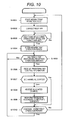
- FIG. 10 is a flowchart illustrating a processing procedure performed by a communication device 50 operating as a terminal in a communication network in an intermittent operation (DRX) mode.
- DRX intermittent operation
- FIG. 11 is a flowchart illustrating another exemplary processing procedure performed by the communication device 50 operating as a terminal in a communication network in the intermittent operation (DRX) mode.
- DRX intermittent operation
- FIG. 12 is a diagram illustrating an exemplary communication sequence performed between a communication network and a terminal.
- FIG. 13 is a flowchart illustrating a processing procedure performed by the communication device 50 operating as a terminal corresponding to an occurred event in a communication network in the intermittent operation (DRX) mode.
- DRX intermittent operation
- FIG. 14 is a flowchart illustrating another exemplary processing procedure performed by the communication device 50 operating as a terminal corresponding to an occurred event in a communication network in the intermittent operation (DRX) mode.
- DRX intermittent operation
- FIG. 15 is a diagram illustrating an exemplary communication control procedure between a MTC user, a MTC server, a communication network and a MTC terminal.
- a structure of a network to which the present invention is applied will be described first.
- MTC-related parts will be mainly described but terminals and servers other than MTC may be present in a communication network.
- FIG. 1 schematically illustrates a structure of a communication network to which the present invention is applied.
- the communication network is a third generation mobile communication system whose specification is defined by 3GPP, for example.
- the communication network is configured of at least a base station, and may be arranged with a mobility management entity (MME) of a terminal and a gateway (GW) for an external network.
- MME mobility management entity
- GW gateway
- the external network described herein is an IP (Internet Protocol) network, for example.
- the terminals accommodated in the communication network include MTC terminals not directly used by persons for communication such as meters, automatic vendors and electronic advertisements.
- the MTC terminal is a terminal for making communication with a MTC user via a communication network, a MTC server or the like.
- the MTC user is a user utilizing MTC. For example, person-operating client machines or programs taking persons' works may be considered as part of the MTC users.
- the MTC server is a server present between the MTC user and the MTC terminal, and is directed for converting an application level request from the MTC user into information for the MTC terminal or transmitting the information for the MTC terminal to the MTC terminal via the communication network.
- the server is not particularly limited in a physical meaning, and the functions of the MTC server can be provided in various forms.
- a terminal, a base station, a MME and a GW are arranged, respectively, but multiple ones may be arranged, respectively.
- the MTC server is present outside the GW or on an external network.
- the illustrated structure may be assumed.
- the MTC user other than the operator of the communication network assumes an operator who collects information from the MTC terminal or distributes information to the MTC terminal, for example.
- FIG. 2 schematically illustrates other structure of the communication network to which the present invention is applied. It is mainly different from the exemplary structure of the communication network illustrated in FIG. 1 in that the MTC server is arranged inside the communication network.
- the MTC server is depicted as a physically-independent device in both the exemplary structures of the communication network illustrated in FIG. 1 and FIG. 2 , but the present invention is not limited thereto, and the GW or other device may support the functions of the MTC server, for example.
- FIG. 3 illustrates an exemplary structure of a radio frame transmitted from the base station to the terminal, which is defined by LTE of 3GPP.
- the radio frame is formed in a three-layer hierarchy of time slot (Slot), subframe (Subframe) and radio frame (Radio Frame) in ascending order of time unit.
- a time slot with 0.5 milliseconds is configured of seven OFDM symbols # 0 to # 6 (in the case of unicast transmission), and is a unit of a demodulation processing when being received on the user (mobile station) side.
- a subframe with one millisecond is configured of two successive time slots, and is a transmission time unit of a correction-encoded data packet.
- a radio frame with 10 milliseconds is configured of ten successive subframes # 0 to # 9 (that is, 20 time slots), and is a basic unit for multiplexing of all the physical channels.
- each terminal accommodated in the base station may make communication without mutual interference.
- a minimum unit of radio resource allocation which is directed for blocking successive subcarriers and is called “resource block (RB)”, is defined in LTE.
- a scheduler mounted on the base station allocates radio resources in units of resource block to each user.
- FIG. 4 schematically illustrates how the resource blocks are allocated.
- the scheduler of the base station can allocate the resource blocks per subframe or at intervals of 1 millisecond. Position information of the resource block is called scheduling.
- the scheduling information on uplink from the terminal to the base station and the scheduling information on downlink from the base station to the terminal are both described in the downlink control channel. Each user can recognize the resource blocks allocated to him/her through the control channel.
- subframes, slots or symbols storing control information therein are transmitted from the base station at a predetermined time and frequency.
- the control information described herein is paging information describing call information or scheduling information describing channel allocation, for example.
- Each terminal accommodated in the base station receives and acquires the control information thereby to know network information of the network to which the terminal is connected, or resource allocation of subframes, slots and frequencies.
- the terminal In DRX, the terminal enters the ON state in a predetermined cycle to receive predetermined subframes, slots or symbols of radio frames among the radio frames transmitted from the base station, and enters the OFF (sleep) state in other times. At least the receiver is stopped in the OFF state so that the terminal can achieve a reduction in consumed power.
- FIG. 5 schematically illustrates an exemplary structure of the communication device operating as a terminal in the network of the base station.
- the illustrated communication device 50 includes one or more antennas 51 , an analog processing unit 52 , a digital transmission processing unit 53 , a digital reception processing unit 54 , an application processing unit 55 , and a DRX control unit 56 .
- the digital transmission processing unit 53 performs digital modulation such as OFDM on transmission data requested to transmit by the application processing unit 55 .
- a transmission circuit in the analog processing unit 52 analog-converts a digital transmission signal, further up-converts it to a radio frequency band and amplifies its power to be delivered from the antenna 51 .
- a reception signal at the antenna 51 is amplified with low noise and down-converted in a reception circuit in the analog processing unit 52 , and then digital-converted.
- the digital reception processing unit 54 performs digital demodulation such as OFDM on a digital reception signal, and recovers and passes reception data to the application processing unit 55 .
- the digital reception processing unit 54 performs a synchronization (or pull-in) processing, frequency correction, channel estimation and the like.
- the communication device 50 includes two or more antennas 51 thereby to make spatial multiplex communication.
- One or more antennas 51 may be employed and the present invention is not limited to a specific number of antennas.
- the communication device 50 has a normal operation mode for always operating the communication processing units such as the analog processing unit 52 , the digital transmission processing unit 53 and the digital reception processing unit 54 , and a power-saving mode for turning off at least part of the circuits in the communication processing units thereby to reduce consumed power.
- An exemplary power-saving mode is an intermittent operation mode for intermittently performing DRX or a communication operation of the communication processing units, where at least part of the circuits in the communication processing units is turned off in a period in which the communication operation stops, thereby achieving low consumed power.
- the DRX control unit 56 controls for causing the communication processing units to perform the intermittent communication operation in the intermittent operation mode while the communication device 50 is acquiring necessary information from the communication network.
- the intermittent operation repeatedly switches on and off the communication operation of the communication processing units with a cycle of DRX.
- a rate of the period in which the communication operation is turned on in the cyclic period that is, a duty ratio is low, low consumed power is more effective but a time in which information can be acquired from the communication network is shorter.
- the most basic intermittent operation employs only one DRX cycle, but to the contrary, the network according to the present embodiment is mainly characterized in that a period for the intermittent operation is determined in combination of the cycles of DRX with different lengths in a hierarchy manner. Upper DRX in the hierarchy has a longer cycle than lower DRX. A period using the cycle of the immediately lower DRX is determined based on the information on the cycle of the upper DRX.
- the intermittent operation of the communication processing units is controlled based on the information on the cycle of the DRX.
- a period using the information on the cycle of the lowermost DRX is called “intermittent operation period.”
- the communication device 50 in the intermittent operation mode performs the intermittent operation on the communication processing units only in the intermittent operation period, and keeps at least part of the circuits in the communication processing units in the OFF state (the long sleep state) in the long period other than the intermittent operation period, thereby achieving low consumed power.
- the communication device 50 in the intermittent operation mode activates the communication operation of the communication processing units only in the intermittent operation period thereby to set the intermittent operation period for acquiring necessary information from the communication network.
- the number of cycles or modes of DRX used in a hierarchy manner is not particularly limited.
- the operations of the communication network will be considered.
- the DRX control unit 56 in FIG. 5 uses the information on the cycle T_DRX 1 of the upper DRX 1 to determine a period using the information on the cycle T_DRX 2 of the lower DRX 2 . Since the DRX 2 is the lowermost DRX, the period using the information on the cycle T_DRX 2 corresponds to the intermittent operation period, and in the period, the information on the cycle T_DRX 2 is used to control the intermittent operation of the communication processing units. Since the communication operation stops in the long period other than the intermittent operation period in the intermittent operation mode, at least part of the circuits in the communication processing units is kept in the OFF state (in the long sleep state), thereby achieving low consumed power.
- the communication device 50 in the intermittent operation mode activates the communication operation of the communication processing units only in the intermittent operation period, and thus the cycle T_DRX 1 of the DRX 1 and the cycle T_DRX 2 of the DRX 2 are set in the communication network for the proper intermittent operation period in which necessary information can be acquired from the communication network.
- information on DRX in the communication network including the information on the cycle T_DRX 1 of the DRX 1 and the information on the cycle T_DRX 2 of the DRX 2 will be called “DRX control information.”
- FIG. 6 illustrates an exemplary internal structure of the DRX control unit 56 .
- the DRX control unit 56 includes a DRX information setting unit 61 , a DRX switch unit 62 , a DRX 1 determination unit 63 , a DRX 2 determination unit 64 , and a timing count unit 65 .
- the DRX information setting unit 61 sets the DRX switch unit 62 , the DRX 1 determination unit 63 and the DRX 2 determination unit 64 according to the DRX control information received from the application processing unit 55 .
- the DRX information setting unit 61 uses a timing count signal from the timing count unit 65 to generate a DRX 1 timing signal with the cycle T_DRX 1 of the DRX 1 and a DRX 2 timing signal with the cycle T_DRX 2 of the DRX 2 and to supply them to the DRX switch unit 62 , the DRX 1 determination unit 63 and the DRX 2 determination unit 64 .
- the DRX control information includes information on a duty ratio between the cycle T_DRX 1 of the DRX 1 and the DRX 1 timing signal and a duty ratio between the cycle T_DRX 2 of the DRX 2 and the DRX 2 timing signal.
- the information on the duty ratios described herein may be the values of the duty ratios, or the values directly indicating the length of the ON period and the length of the OFF period of the DRX 1 timing signal and the DRX 2 timing signal.
- the DRX switch unit 62 switches to the period using the DRX 2 timing signal or the intermittent operation period based on the ON/OFF switch timing of the DRX 1 timing signal input from the DRX information setting unit 61 , and inputs an instruction into the DRX 1 determination unit 63 and the DRX 2 determination unit 64 .
- the DRX 1 determination unit 63 compares the DRX 1 timing signal input from the DRX information setting unit 61 with the timing count signal input from the timing count unit 65 , and controls the intermittent operation of the digital reception processing unit 54 and the analog processing unit 52 in the period other than the intermittent operation period in the intermittent operation mode.
- the DRX 2 determination unit 64 compares the DRX 2 timing signal input from the DRX information setting unit 61 with the timing count signal input from the timing count unit 65 , and controls the intermittent operation of the digital transmission processing unit 53 , the digital reception processing unit 54 and the analog processing unit 52 in the intermittent operation period.
- FIG. 7 illustrates exemplary DRX using DRX 1 with a long cycle T_DRX 1 and DRX 2 with a short cycle T_DRX 2 in a hierarchy manner (T_DRX 1 ⁇ T_DRX 2 ).
- the intermittent operation period is as long as the ON period of the upper DRX 1 timing signal and the communication operation is performed only in the ON period of the lower DRX 2 timing signal in the intermittent operation period.
- the ON period of the upper DRX 1 timing signal is inevitably longer than the ON period of the lower DRX 2 timing signal.
- the intermittent operation period in which the communication processing units are intermittently operated based on the immediately lower DRX 2 timing signal is set based on the upper DRX 1 timing signal in the hierarchy DRX.
- the DRX switch unit 62 when entering the ON period of the DRX 1 timing signal, determines to start the intermittent operation period, and entering the OFF period of the DRX 1 timing signal, determines to terminate the intermittent operation period.
- the DRX 1 determination unit 63 keeps at least part of the circuits in the digital transmission processing unit 53 , the digital reception processing unit 54 and the analog processing unit 52 in the OFF state in other than the intermittent operation period (that is, puts the terminal in the long sleep state).
- the DRX 2 determination unit 64 determines ON/OFF of the DRX 2 timing signal, and turns on the digital transmission processing unit 53 , the digital reception processing unit 54 and the analog processing unit 52 in the ON period of the DRX 2 timing signal, and waits for the control information to be received from the radio frames or the communication network (the base station).
- the DRX 2 determination unit 64 turns off the digital transmission processing unit 53 , the digital reception processing unit 54 and the analog processing unit 52 in the OFF period of the DRX 2 timing signal (that is, puts the terminal in the short sleep state).
- the cycles of DRX with different lengths are used in a hierarchy manner as illustrated in FIG. 7 so that the terminal can acquire necessary information from the communication network in the short DRX cycle while achieving a reduction in consumed power of the terminal in the long DRX cycle.
- the number of cycles of the hierarchy DRX is not limited to two.
- the DRX unit is a subframe, but reception is possible in other unit.
- FIG. 8 illustrates other exemplary DRX using DRX 1 with a long cycle T_DRX 1 and DRX 2 with a short cycle T_DRX 2 in a hierarchy manner.
- T_DRX 1 >T_DRX 2 is assumed.
- a rise of the upper DRX 1 timing signal is used to determine the start point and the end point of the intermittent operation period, and thus the length of the ON period is meaningless. Since the communication operation is performed only in the ON period of the lower DRX 2 timing signal in the intermittent operation period, when a duty ratio is made higher, the reception chances increase but lower consumed power is less effective.
- the intermittent operation period for intermittently operating the communication processing units based on the immediately lower DRX 2 timing signal is set based on the upper DRX 1 timing signal in the hierarchy DRX. While the intermittent operation period is in the ON period of the DRX 1 timing signal in the example illustrated in FIG. 7 , the intermittent operation period starts when the DRX 1 timing signal is turned on outside the intermittent operation period and the intermittent operation period ends when the DRX 1 timing signal is turned on in the intermittent operation period in the example illustrated in FIG. 8 (that is, whenever the DRX 1 timing signal is turned on, the intermittent operation period alternately starts and ends in a repeated manner).
- the DRX switch unit 62 determines to start the intermittent operation period when the DRX 1 timing signal is turned on not in the DRX 2 mode.
- the DRX switch unit 62 determines to terminate the intermittent operation period when the DRX 1 timing signal is turned on in the intermittent operation period.
- the DRX 2 determination unit 64 determines ON/OFF of the DRX 2 timing signal in the intermittent operation period, and turns on the digital transmission processing unit 53 , the digital reception processing unit 54 and the analog processing unit 52 and waits for the control information to be received from the communication network (the base station) in the ON period of the DRX 2 timing signal.
- the DRX 2 determination unit 64 turns off the digital transmission processing unit 53 , the digital reception processing unit 54 and the analog processing unit 52 in the OFF period of the DRX 2 timing signal (that is, puts the terminal in the short sleep state).
- the DRX 1 determination unit 63 turns off the digital transmission processing unit 53 , the digital reception processing unit 54 and the analog processing unit 52 in the period other than the intermittent operation period (that is, puts the terminal in the long sleep state).
- the cycles of DRX with different lengths are used in a hierarchy manner as illustrated in FIG. 8 so that the terminal can acquire necessary information from the communication network in the short DRX cycle while achieving a reduction in consumed power of the terminal in the long DRX cycle.
- the number of cycles of the hierarchy DRX is not limited to two.
- the DRX unit is a subframe, but reception is possible in other unit.
- FIG. 9 illustrates still another exemplary DRX using the DRX 1 mode with a long cycle T_DRX 1 and the DRX 2 mode with a short cycle T_DRX 2 in a hierarchy manner.
- T_DRX 1 >T_DRX 2 is assumed.
- the intermittent operation period for intermittently operating the communication processing units based on the immediately lower DRX 2 timing signal is set based on the upper DRX 1 timing in the hierarchy DRX.
- the intermittent operation period is in the ON period of the DRX 1 timing signal similarly as in the example illustrated in FIG. 7 . While the communication operation is performed in the ON period of the DRX 2 timing signal in the intermittent operation period in the example illustrated in FIG.
- the communication operation starts when the DRX 2 timing signal is turned on while the communication operation is stopping in the intermittent operation period, and the communication operation stops when the DRX 2 timing signal is turned on during the communication operation (that is, whenever the DRX 2 timing signal is turned on, the communication operation alternately starts and stops in a repeated manner) in the example illustrated in FIG. 9 .
- the DRX switch unit 62 determines to start the intermittent operation period when entering the ON period of the DRX 1 timing signal, and determines to terminate the intermittent operation period when entering the OFF period of the DRX 1 timing signal.
- the DRX 1 determination unit 63 keeps at least part of the circuits in the digital transmission processing unit 53 , the digital reception processing unit 54 and the analog processing unit 52 in the OFF state in other than the intermittent operation period (that is, puts the terminal in the long sleep state).
- the DRX 2 determination unit 64 starts the communication operation when the DRX 2 timing signal is turned on while the communication processing units such as the digital transmission processing unit 53 , the digital reception processing unit 54 and the analog processing unit 52 stop the communication operation, and waits for the control information to be received from the radio frames or the communication network (the base station).
- the communication processing units such as the digital transmission processing unit 53 , the digital reception processing unit 54 and the analog processing unit 52 stop the communication operation, and waits for the control information to be received from the radio frames or the communication network (the base station).
- the DRX 2 timing signal is turned on during the communication operation of the communication processing units, the communication operation of the communication processing units stops (that is, the terminal is put in the sleep state). Thereafter, whenever the DRX 2 timing signal is turned on, the reception waiting state and the (short) sleep state are alternately switched.
- the cycles of DRX with different lengths are used in a hierarchy manner as illustrated in FIG. 9 , the terminal can acquire necessary information from the communication network in the short DRX cycle while achieving a reduction in consumed power of the terminal in the long DRX cycle.
- the number of cycles of the hierarchy DRX is not limited to two.
- the DRX unit is a subframe, but reception is possible in other unit.
- the radio frame are continuously received only in the intermittent operation period in the intermittent operation mode.
- the communication processing units may exit the intermittent operation period and may be turned off without waiting for the intermittent operation period determined based on the DRX 1 timing signal to end. Thereby, the terminal can further achieve a reduction in consumed power.
- the MTC terminal For a timing when the MTC terminal corrects the receiver, it is assumed that pull-in or synchronization is performed when the receiver is not in ON after the intermittent operation period starts. Thereby, it is possible to correct the receiver in order to keep the reception quality while achieving a reduction in consumed power when the communication processing units are in the OFF (sleep) state in the period other than the intermittent operation period determined by the DRX 1 timing signal.
- the receiver may be corrected in other timing. For example, also in the OFF state other than the intermittent operation period, the terminal may voluntarily make a correction. In this case, the terminal temporarily enters the ON state.
- FIG. 10 illustrates the processing procedure performed by the communication device 50 operating as a terminal in the communication network in the intermittent operation (DRX) mode in a form of flowchart.
- the terminal when entering the intermittent operation mode, uses the long cycle T_DRX 1 and the short cycle T_DRX 2 in a hierarchy manner.
- step S 1001 When the intermittent operation mode starts according to the determination by the DRX switch unit 62 (step S 1001 ), the digital reception processing unit 54 performs a correction processing such as synchronization or pull-in before the communication processing units are turned on (step S 1002 ).
- the DRX switch unit 62 monitors the DRX 1 timing signal and waits for a timing of entering the intermittent operation period to arrive (No in step S 1003 ). Then, when the timing of entering the intermittent operation period arrives (Yes in step S 1003 ), the terminal enters the intermittent operation period (step S 1004 ).
- the DRX 2 determination unit 64 compares the DRX 2 timing signal input from the DRX information setting unit 61 with the timing count signal input from the timing count unit 65 , and waits for a period for performing the reception operation to arrive (No in step S 1005 ).
- the DRX 2 determination unit 64 turns on the receiver, that is, the digital reception processing unit 54 and the analog processing unit 52 , and receives predetermined control information from the communication network (step S 1006 ).
- the control information described herein is paging information describing call information or scheduling information describing channel allocation, for example.
- the control information received from the communication network is analyzed to check whether a channel is allocated to the terminal (step S 1007 ).
- the digital reception processing unit 54 and the analog processing unit 52 receive the allocated channel (step S 1008 ), and performs processing according to the contents received in the application processing unit 55 (step S 1009 ).
- the DRX switch unit 62 checks whether to continue the intermittent operation period based on the DRX 1 timing signal (step S 1010 ).
- the processing returns to step S 1005 to wait for the period for performing the reception operation to arrive.
- the processing returns to step S 1001 .
- FIG. 11 illustrates another exemplary processing procedure performed by the communication device 50 operating as a terminal in the communication network in the intermittent operation (DRX) mode in a form of flowchart.
- the terminal when entering the intermittent operation mode, uses the long cycle T_DRX 1 and the short cycle T_DRX 2 in a hierarchy manner (ditto).
- the DRX switch unit 62 monitors the DRX 1 timing signal, and waits for a timing of entering the intermittent operation period to arrive (No in step S 1102 ). Then, when the timing of entering the intermittent operation period arrives (Yes in step S 1102 ), the terminal enters the intermittent operation period (step S 1103 ).
- the receiver or the digital reception processing unit 54 When entering the intermittent operation period, the receiver or the digital reception processing unit 54 performs the correction processing such as synchronization or pull-in before the receiver is turned on (step S 1104 ).
- the DRX 2 determination unit 64 compares the DRX 2 timing signal input from the DRX information setting unit 61 with the timing count signal input from the timing count unit 65 , and waits for a period for performing the reception operation to arrive (No in step S 1105 ).
- the DRX 2 determination unit 64 turns on the receiver, that is, the digital reception processing unit 54 and the analog processing unit 52 , and receives predetermined control information from the communication network (step S 1106 ).
- step S 1107 the control information received from the communication network is analyzed and a check is made as to whether a channel is allocated to the terminal. Then, when a channel is allocated (Yes in step S 1107 ), the digital reception processing unit 54 and the analog processing unit 52 receive the allocated channel (step S 1108 ), and perform processing according to the contents received in the application processing unit 55 (step S 1109 ).
- the DRX switch unit 62 checks whether to continue the intermittent operation period based on the DRX 1 timing signal (step S 1110 ).
- the processing returns to step S 1105 to wait for the period for performing the reception operation to arrive.
- the processing returns to step S 1001 .
- FIG. 12 illustrates an exemplary communication sequence performed between the communication network and the MTC terminal.
- the base station In the communication network, for example, the base station generates DRX control information necessary for performing DRX at the terminal (SEQ 1201 ).
- the DRX control information is generated for using a plurality of DRX modes with different cycles in a hierarchy manner.
- the DRX control information includes the information on the cycle T_DRX 1 of the DRX 1 and the information on the cycle T_DRX 2 of the DRX 2 . Then, the generated DRX control information is notified to the MTC terminal from the communication network (SEQ 1202 ).
- the MTC terminal sets the cycles and the duty ratios of the DRX 1 timing signal and the DRX 2 timing signal based on the received DRX control information, and performs DRX according to any operation procedure illustrated in FIG. 7 to FIG. 9 , for example (SEQ 1203 ).
- the communication network generates system information, paging information, scheduling information and the like (SEQ 1204 ). Then, after the cycles and the duty ratios of the DRX 1 timing signal and the DRX 2 timing signal are set for the MTC terminal as described above, the system information, the paging information, the scheduling information and the like are transmitted to the MTC terminal so as to conform to the cycles (or the subframes in which the MTC terminal performs the reception operation) (SEQ 1205 ).
- the MTC terminal When receiving the system information, the paging information, the scheduling information and the like, the MTC terminal performs processing according to the information (SEQ 1206 ). Thereby, the MTC terminal can both reduce consumed power with the long cycle T_DRX 1 (the long sleep state) and acquire necessary information from the communication network.
- DRX in the MTC terminal is basically set from the communication network side.
- DRX is set from the communication network side according to a communication frequency of the network information.
- the MTC terminal is in the sleep state for a long time, but communication may be needed due to an occurrence of an event at a timing other than the initial schedule.
- the event described herein may include an emergency situation or failure occurring in the MTC terminal.
- the communication network and the MTC terminal need to properly operate.
- the DRX control system depending on an occurred event will be considered.
- the DRX 1 timing signal driven at the cycle T_DRX 1 a is typically used to determine the intermittent operation period, but when an event occurs, the cycle is switched to the DRX 1 timing signal driven at T_DRX 1 b to determine the intermittent operation period.
- the DRX information setting unit 61 may change the DRX 1 cycle from T_DRX 1 a to T_DRX 1 b to change the DRX 1 timing signal, and the DRX switch unit 62 may determine the intermittent operation period by use of the changed DRX 1 timing signal. With the cycle switching, the terminal can rapidly make connection to the communication network when an event occurs.
- FIG. 13 illustrates a processing procedure performed by the communication device 50 operating as a terminal corresponding to an occurred event in the communication network in the intermittent operation (DRX) mode in a form of flowchart.
- DRX intermittent operation
- the DRX information setting unit 61 first sets the cycle of the DRX 1 at T_DRX 1 a and then generates the DRX 1 timing signal.
- step S 1302 a check is made as to whether a predetermined event has occurred in the intermittent operation mode (in the period not in the intermittent operation period) (step S 1302 ).
- an occurrence of an even at the application layer level in the MTC terminal or sensor detection is assumed.
- the present invention is not limited to a specific event detection method.
- the DRX information setting unit 61 switches the cycle of the DRX 1 from T_DRX 1 a to T_DRX 1 b thereby to change the DRX 1 timing signal (step S 1303 ). Consequently, the DRX switch unit 62 uses the changed DRX 1 timing signal to determine the intermittent operation period.
- the DRX information setting unit 61 when a predetermined event has not occurred (No in step S 1302 ), the DRX information setting unit 61 generates the DRX 1 timing signal with the cycle of the DRX 1 kept at T_DRX 1 a , and the DRX switch unit 62 uses the DRX 1 timing signal to determine the intermittent operation period.
- the DRX switch unit 62 monitors the DRX 1 timing signal and waits for a timing of entering the intermittent operation period to arrive (No in step S 1304 ). Then, when the timing of entering the intermittent operation period arrives (Yes in step S 1304 ), the terminal enters the intermittent operation period (step S 1305 ).
- the receiver or the digital reception processing unit 54 When entering the intermittent operation period, the receiver or the digital reception processing unit 54 performs the correction processing such as synchronization or pull-in prior to activating the reception operation (step S 1306 ).
- the DRX 2 determination unit 64 compares the DRX 2 timing signal input from the DRX information setting unit 61 with the timing count signal input from the timing count unit 65 , and waits for a period for performing the reception operation to arrive (No in step S 1307 ).
- the DRX 2 determination unit 64 turns on the receiver, that is, the digital reception processing unit 54 and the analog processing unit 52 , and receives predetermined control information from the communication network (step S 1308 ).
- step S 1309 the control information received from the communication network is analyzed and a check is made as to whether a channel is allocated to the terminal. Then, when a channel is allocated (Yes in step S 1309 ), the digital reception processing unit 54 and the analog processing unit 52 receive the allocated channel (step S 1310 ), and performs processing according to the contents received in the application processing unit 55 (step S 1311 ).
- the DRX switch unit 62 checks whether to continue the intermittent operation period based on the DRX 1 timing signal (step S 1312 ).
- the processing returns to step S 1307 to wait for a period for performing the reception operation to arrive.
- the processing returns to step S 1301 .
- FIG. 14 illustrates another exemplary processing procedure performed by the communication device 50 operating as a terminal corresponding to an occurred event in the communication network in the intermittent operation (DRX) mode in a form of flowchart.
- DRX intermittent operation
- the DRX information setting unit 61 sets the cycle of the DRX 1 at T_DRX 1 a and generates the DRX 1 timing signal.
- step S 1402 a check is made as to whether a predetermined event has occurred in the intermittent operation mode (in the period not in the intermittent operation period) (step S 1402 ).
- step S 1402 when a predetermined event has occurred (Yes in step S 1402 ), the terminal exits the intermittent operation mode and enters the normal communication state to always perform the reception operation (step S 1403 ). Then, the terminal issues a request of connecting to the communication network (the base station) (step S 1404 ), and when connection is established, performs the communication processing according to the predetermined contents (step S 1405 ). Thereafter, the terminal returns to step S 1401 .
- the DRX switch unit 62 monitors the DRX 1 timing signal and waits for a timing of entering the intermittent operation period to arrive (No in step S 1406 ). Then, when the timing of entering the intermittent operation period arrives (Yes in step S 1406 ), the terminal enters the intermittent operation period (step S 1407 ).
- the receiver or the digital reception processing unit 54 When entering the intermittent operation period, the receiver or the digital reception processing unit 54 performs the correction processing such as synchronization or pull-in before the receiver is turned on (step S 1408 ).
- the DRX 2 determination unit 64 compares the DRX 2 timing signal input from the DRX information setting unit 61 with the timing count signal input from the timing count unit 65 , and waits for a period for performing the reception operation to arrive (No in step S 1409 ).
- the DRX 2 determination unit 64 turns on the receiver, that is, the digital reception processing unit 54 and the analog processing unit 52 , and receives predetermined control information from the communication network (step S 1410 ).
- step S 1411 the control information received from the communication network is analyzed, and a check is made as to whether a channel is allocated to the terminal (step S 1411 ). Then, when a channel is allocated (Yes in step S 1411 ), the digital reception processing unit 54 and the analog processing unit 52 receive the allocated channel (step S 1412 ) and perform processing according to the contents received in the application processing unit 55 (step S 1413 ).
- the DRX switch unit 62 checks whether to continue the intermittent operation period based on the DRX 1 timing signal (step S 1414 ).
- the processing returns to step S 1409 to wait for a period for performing the reception operation to arrive.
- the processing returns to step S 1401 .
- MTC applications may include meters, automatic vendors, electronic advertisements and the like.
- an intention of the MTC user is desirably reflected on the communication contents and the communication schedule of the MTC terminal.
- the communication schedule largely has a relationship with DRX.
- the communication schedule is longer, such as daily, weekly and monthly, unlike the typical communication.
- the communication schedule desired by the MTC user needs to be put under the DRX control on the communication network side in order to efficiently apply the DRX control to the system. Therefore, it is desirable that a function of notifying the communication schedule desired by the MTC user to the communication network is inside the communication network or outside the communication network.
- a MTC server is assumed for realizing the function.
- FIG. 15 illustrates an exemplary communication control procedure between the MTC user, the MTC server, the communication network and the MTC terminal.
- the MTC user, the MTC server, the communication network and the MTC terminal are classified not physically but logically.
- the MTC server can also have the functions of the MTC user or the GW in the communication network can also have the functions of the MTC server.
- FIG. 15 only exchange of information at the logic level and in the application layer is noted, and ACK/NACK or retransmission when a communication error occurs in the lower layer is omitted. Any protocol is applicable to the protocol in the lower layer.
- the functions of the MTC server for controlling DRX with respect to the communication network may have the following.
- the information input from the MTC user may be manually input by the MTC user or may be automatically generated by the MTC user (the client machine).
- the input method is not limited.
- the MTC server may simply notify the schedule information as time information to the communication network or may convert and notify it into a unit (radio frame, subframe, slot or the like) according to the frame structure of the communication network to the communication network.
- the communication network When receiving the schedule information from the MTC server, the communication network generates control information on the actual DRX from the schedule, and controls DRX of the target MTC terminal.
- the DRX control information is notified to the MTC terminal via the base station.
- the schedule information received from the MTC server can be longer (time, day, week, month or the like) as time information handled by the communication network.
- the longest DRX cycle needs to be shorter than the schedule cycle set by the MTC user in the DRX setting at the communication network level.
- the embodiment in which the present invention is applied to the communication network based on the data communication specification defined by LTE of 3GPP has been mainly described in the present specification, but the present invention is not limited thereto.
- the present invention is applicable to various types of communication networks configured of the base stations accommodating terminals.
- the embodiment in which the present invention is applied to the MTC terminal not directly used by persons for communication has been mainly described in the present specification, but the present invention is not limited thereto.
- the present invention is applicable to various types of terminals directly used by persons for communication other than MTC, or various types of communication systems other than illustrated ones in FIG. 1 and FIG. 2 .
Abstract
Description
- Patent Document 1: Japanese Patent No. 2669891
- Patent Document 2: Japanese Patent No. 3270306
- Non-Patent Document 1: 3GPP TS36.321, “Evolved Universal Terrestrial Radio Access (E-UTRA) Medium Access Control (MAC) protocol specification (Release 9)”
- 50 Communication device
- 51 Antenna
- 52 Analog processing unit
- 53 Digital transmission processing unit
- 54 Digital reception processing unit
- 55 Application processing unit
- 56 DRX control unit
- 61 DRX information setting unit
- 62 DRX switch unit
- 63 DRX1 determination unit
- 64 DRX2 determination unit
- 65 Timing count unit
Claims (16)
Applications Claiming Priority (3)
| Application Number | Priority Date | Filing Date | Title |
|---|---|---|---|
| JP2010-145645 | 2010-06-25 | ||
| JP2010145645A JP2012010202A (en) | 2010-06-25 | 2010-06-25 | Communication apparatus and communication method, and communication system |
| PCT/JP2011/061003 WO2011162039A1 (en) | 2010-06-25 | 2011-05-12 | Communication apparatus, communication method and communication system |
Related Parent Applications (1)
| Application Number | Title | Priority Date | Filing Date |
|---|---|---|---|
| PCT/JP2011/061003 A-371-Of-International WO2011162039A1 (en) | 2010-06-25 | 2011-05-12 | Communication apparatus, communication method and communication system |
Related Child Applications (1)
| Application Number | Title | Priority Date | Filing Date |
|---|---|---|---|
| US14/744,279 Continuation US9769753B2 (en) | 2010-06-25 | 2015-06-19 | Communication device and communication method as well as communication system |
Publications (2)
| Publication Number | Publication Date |
|---|---|
| US20130084845A1 US20130084845A1 (en) | 2013-04-04 |
| US9100912B2 true US9100912B2 (en) | 2015-08-04 |
Family
ID=45371240
Family Applications (2)
| Application Number | Title | Priority Date | Filing Date |
|---|---|---|---|
| US13/702,601 Active 2032-01-03 US9100912B2 (en) | 2010-06-25 | 2011-05-12 | Communication device, and communication method as well as communication system |
| US14/744,279 Active 2032-01-21 US9769753B2 (en) | 2010-06-25 | 2015-06-19 | Communication device and communication method as well as communication system |
Family Applications After (1)
| Application Number | Title | Priority Date | Filing Date |
|---|---|---|---|
| US14/744,279 Active 2032-01-21 US9769753B2 (en) | 2010-06-25 | 2015-06-19 | Communication device and communication method as well as communication system |
Country Status (6)
| Country | Link |
|---|---|
| US (2) | US9100912B2 (en) |
| EP (1) | EP2587866B1 (en) |
| JP (1) | JP2012010202A (en) |
| CN (1) | CN103026763B (en) |
| RU (1) | RU2012154923A (en) |
| WO (1) | WO2011162039A1 (en) |
Families Citing this family (36)
| Publication number | Priority date | Publication date | Assignee | Title |
|---|---|---|---|---|
| JP2012169969A (en) | 2011-02-16 | 2012-09-06 | Sony Corp | Radio communication device, base station, radio communication method, program, and radio communication system |
| EP2804427B1 (en) | 2012-01-13 | 2020-07-29 | Fujitsu Limited | Radio terminal, wireless communication system, and wireless communication method |
| JP5982991B2 (en) * | 2012-04-25 | 2016-08-31 | セイコーエプソン株式会社 | Receiver drive control method and receiver |
| WO2013161084A1 (en) * | 2012-04-27 | 2013-10-31 | 富士通株式会社 | Base station device, mobile station device, and communication method |
| EP3735007A1 (en) | 2012-05-09 | 2020-11-04 | Interdigital Patent Holdings, Inc. | Handling mtc long drx cycle/sleep lengths |
| US9407391B2 (en) * | 2012-05-11 | 2016-08-02 | Intel Corporation | User equipment power savings for machine type communications |
| GB2502275B (en) | 2012-05-21 | 2017-04-19 | Sony Corp | Telecommunications systems and methods |
| GB2502274B (en) | 2012-05-21 | 2017-04-19 | Sony Corp | Telecommunications systems and methods |
| US8868026B2 (en) * | 2012-08-30 | 2014-10-21 | Nokia Solutions And Networks Oy | Sending BCCH modification info/ETWS information to UEs in enhanced cell PCH in one DRX cycle |
| GB2506152C (en) | 2012-09-21 | 2019-12-11 | Sony Corp | Telecommunications systems and methods |
| CN103686866A (en) * | 2012-09-26 | 2014-03-26 | 中兴通讯股份有限公司 | Wireless resource adjustment method and device thereof |
| US9338070B2 (en) * | 2012-11-02 | 2016-05-10 | Industrial Technology Research Institute | System and method for operating M2M devices |
| GB2508241A (en) * | 2012-11-27 | 2014-05-28 | Nec Corp | Scheduled Discontinuous Reception in a Mobile Device |
| WO2014087145A1 (en) * | 2012-12-03 | 2014-06-12 | Sony Corporation | Transmission of control information to reduced bandwidth terminals |
| EP2942983A4 (en) * | 2013-01-07 | 2016-08-17 | Nec Corp | Mobile communication system, service platform, network parameter control method, and computer-readable medium |
| GB2510141A (en) * | 2013-01-24 | 2014-07-30 | Sony Corp | Mobile communications network including reduced capability devices |
| GB2510138A (en) * | 2013-01-24 | 2014-07-30 | Sony Corp | Allocating communications resources within different frequency ranges according to the relative capability of a communications device |
| GB2510137A (en) * | 2013-01-24 | 2014-07-30 | Sony Corp | Mobile communications network including reduced capability devices |
| GB2510140A (en) | 2013-01-24 | 2014-07-30 | Sony Corp | Virtual carrier for reduced capability wireless devices |
| US9326122B2 (en) | 2013-08-08 | 2016-04-26 | Intel IP Corporation | User equipment and method for packet based device-to-device (D2D) discovery in an LTE network |
| US9564958B2 (en) | 2013-08-08 | 2017-02-07 | Intel IP Corporation | Power saving mode optimizations and related procedures |
| CN105393470B (en) | 2013-08-08 | 2018-11-02 | 英特尔Ip公司 | The methods, devices and systems adjusted for the electrical tilt angle in multi-input multi-output system |
| CN104468425B (en) * | 2013-09-13 | 2019-02-26 | 华为技术有限公司 | A kind of remote radio unit (RRU) channel correcting method, device and system |
| JP2015090277A (en) | 2013-11-05 | 2015-05-11 | セイコーエプソン株式会社 | Satellite signal receiver |
| JP6318565B2 (en) | 2013-11-13 | 2018-05-09 | セイコーエプソン株式会社 | Semiconductor device and electronic equipment |
| JP2015108565A (en) | 2013-12-05 | 2015-06-11 | セイコーエプソン株式会社 | Integrated circuit for receiving satellite signal |
| JP6504167B2 (en) * | 2014-07-14 | 2019-04-24 | 日本電気株式会社 | Method and apparatus for communication management |
| US20180049121A1 (en) * | 2015-03-23 | 2018-02-15 | Nec Corporation | Radio communication system, radio communication network, radio terminal, and radio communication method |
| US20160337966A1 (en) * | 2015-05-13 | 2016-11-17 | Simmonds Precision Products, Inc. | Low power data transmission protocol |
| MX367998B (en) | 2015-05-13 | 2019-09-13 | Ericsson Telefon Ab L M | Paging coordination between wireless communication device and core network node. |
| JP6152904B2 (en) * | 2016-02-25 | 2017-06-28 | 富士通株式会社 | Wireless terminal, wireless communication system, base station, and wireless communication method |
| JP6269716B2 (en) * | 2016-04-15 | 2018-01-31 | セイコーエプソン株式会社 | Receiver drive control method and receiver |
| EP3337244A1 (en) * | 2016-12-19 | 2018-06-20 | Gemalto M2M GmbH | Method for data transmission in a cellular network with reconfigurable radio frame structure settings |
| US11665667B2 (en) | 2018-05-18 | 2023-05-30 | Sony Group Corporation | Flexible paging procedure |
| JP6679658B2 (en) * | 2018-06-01 | 2020-04-15 | ソニー株式会社 | Mobile terminal, system and method for protocol mode switching |
| US20220322485A1 (en) * | 2019-05-27 | 2022-10-06 | Beijing Xiaomi Mobile Software Co., Ltd. | Discontinuous reception method and apparatus, electronic device and computer readable storage medium |
Citations (14)
| Publication number | Priority date | Publication date | Assignee | Title |
|---|---|---|---|---|
| JP2669891B2 (en) | 1989-04-24 | 1997-10-29 | 日本電信電話株式会社 | Intermittent reception control method in mobile communication |
| JP3270306B2 (en) | 1995-09-14 | 2002-04-02 | 株式会社東芝 | Mobile communication system, mobile communication network and mobile communication device used in this system |
| US20030086387A1 (en) * | 2001-11-05 | 2003-05-08 | Uniden Corporation | Radio terminal, radio synchronization system having no base station, and recording medium |
| US20050202813A1 (en) * | 2004-03-10 | 2005-09-15 | Kabushiki Kaisha Toshiba | Mobile radio terminal apparatus |
| WO2007049698A1 (en) | 2005-10-28 | 2007-05-03 | Nec Corporation | Mobile communication system, base station, mobile station, and power-saving transmission/reception method used in them |
| WO2008137596A1 (en) | 2007-05-01 | 2008-11-13 | Qualcomm Incorporated | Extended microsleep for communications |
| JP2010021816A (en) | 2008-07-11 | 2010-01-28 | Panasonic Corp | Wireless slave unit for meter reading |
| JP2010050969A (en) | 2008-08-22 | 2010-03-04 | Ntt Docomo Inc | Method and apparatus for dynamically indicating change of discontinuous reception status of user equipment |
| JP2010056740A (en) | 2008-08-27 | 2010-03-11 | Sharp Corp | Communication system, communication apparatus, communication control method, and communication control program |
| CN101682888A (en) | 2007-01-30 | 2010-03-24 | 交互数字技术公司 | Implicit DRX cycle length adjustment control in LTE_active mode |
| US20100120378A1 (en) * | 2007-04-24 | 2010-05-13 | Ntt Docomo, Inc. | Mobile communication method, radio base station, mobile station, and processor |
| US20100144358A1 (en) * | 2008-10-08 | 2010-06-10 | Michio Iguchi | Wireless base station, wireless terminal and wireless communication system |
| US20110032894A1 (en) * | 2008-02-29 | 2011-02-10 | Ntt Docomo, Inc. | Mobile communication system, base station apparatus, user apparatus and method |
| US20110051645A1 (en) * | 2009-09-02 | 2011-03-03 | Electronics And Telecommunications Research Institute | Sensor network system and communication method thereof |
Family Cites Families (4)
| Publication number | Priority date | Publication date | Assignee | Title |
|---|---|---|---|---|
| CN101039208B (en) * | 2006-03-13 | 2011-04-06 | 大唐移动通信设备有限公司 | Method for updating working state of user terminal |
| CN101047951B (en) * | 2006-03-27 | 2010-06-16 | 中兴通讯股份有限公司 | Media access control station transport method in radio communication system |
| US7916675B2 (en) * | 2006-06-20 | 2011-03-29 | Nokia Corporation | Method and system for providing interim discontinuous reception/transmission |
| CN101534544B (en) * | 2008-03-12 | 2012-02-08 | 中兴通讯股份有限公司 | Control method for discontinuous reception and device as well as starting point setting method thereof |
-
2010
- 2010-06-25 JP JP2010145645A patent/JP2012010202A/en not_active Withdrawn
-
2011
- 2011-05-12 CN CN201180029963.9A patent/CN103026763B/en active Active
- 2011-05-12 RU RU2012154923/07A patent/RU2012154923A/en not_active Application Discontinuation
- 2011-05-12 EP EP11797926.0A patent/EP2587866B1/en active Active
- 2011-05-12 WO PCT/JP2011/061003 patent/WO2011162039A1/en active Application Filing
- 2011-05-12 US US13/702,601 patent/US9100912B2/en active Active
-
2015
- 2015-06-19 US US14/744,279 patent/US9769753B2/en active Active
Patent Citations (16)
| Publication number | Priority date | Publication date | Assignee | Title |
|---|---|---|---|---|
| JP2669891B2 (en) | 1989-04-24 | 1997-10-29 | 日本電信電話株式会社 | Intermittent reception control method in mobile communication |
| JP3270306B2 (en) | 1995-09-14 | 2002-04-02 | 株式会社東芝 | Mobile communication system, mobile communication network and mobile communication device used in this system |
| US20030086387A1 (en) * | 2001-11-05 | 2003-05-08 | Uniden Corporation | Radio terminal, radio synchronization system having no base station, and recording medium |
| US20050202813A1 (en) * | 2004-03-10 | 2005-09-15 | Kabushiki Kaisha Toshiba | Mobile radio terminal apparatus |
| US20090161587A1 (en) | 2005-10-28 | 2009-06-25 | Nec Corporation | Mobile communication system, base station, mobile station, and power-saving transmission and reception method used in them |
| WO2007049698A1 (en) | 2005-10-28 | 2007-05-03 | Nec Corporation | Mobile communication system, base station, mobile station, and power-saving transmission/reception method used in them |
| CN101682888A (en) | 2007-01-30 | 2010-03-24 | 交互数字技术公司 | Implicit DRX cycle length adjustment control in LTE_active mode |
| US20100120378A1 (en) * | 2007-04-24 | 2010-05-13 | Ntt Docomo, Inc. | Mobile communication method, radio base station, mobile station, and processor |
| US20090016252A1 (en) * | 2007-05-01 | 2009-01-15 | Qualcomm Incorporated | Extended microsleep for communications |
| WO2008137596A1 (en) | 2007-05-01 | 2008-11-13 | Qualcomm Incorporated | Extended microsleep for communications |
| US20110032894A1 (en) * | 2008-02-29 | 2011-02-10 | Ntt Docomo, Inc. | Mobile communication system, base station apparatus, user apparatus and method |
| JP2010021816A (en) | 2008-07-11 | 2010-01-28 | Panasonic Corp | Wireless slave unit for meter reading |
| JP2010050969A (en) | 2008-08-22 | 2010-03-04 | Ntt Docomo Inc | Method and apparatus for dynamically indicating change of discontinuous reception status of user equipment |
| JP2010056740A (en) | 2008-08-27 | 2010-03-11 | Sharp Corp | Communication system, communication apparatus, communication control method, and communication control program |
| US20100144358A1 (en) * | 2008-10-08 | 2010-06-10 | Michio Iguchi | Wireless base station, wireless terminal and wireless communication system |
| US20110051645A1 (en) * | 2009-09-02 | 2011-03-03 | Electronics And Telecommunications Research Institute | Sensor network system and communication method thereof |
Non-Patent Citations (4)
| Title |
|---|
| "3rd Generation Partnership Project; Technical Specification Group Radio Access Network; Evolved Universal Terrestrial Radio Access (E-UTRA) Medium Access Control (MAC) protocol specification (Release 9)" Technical Specification, 3GPP TS 36.321 V9.0.0, Sep. 2009, 47 pages. |
| Chinese Office Action issued on Feb. 17, 2015 in patent application No. 201180029963.9. |
| International Search Report Issued Aug. 16, 2011 in PCT/JP11/61003 Filed May 12, 2011. |
| U.S. Appl. No. 13/981,641, filed Jul. 25, 2013, Takano. |
Also Published As
| Publication number | Publication date |
|---|---|
| CN103026763A (en) | 2013-04-03 |
| WO2011162039A1 (en) | 2011-12-29 |
| US20150289206A1 (en) | 2015-10-08 |
| JP2012010202A (en) | 2012-01-12 |
| EP2587866A1 (en) | 2013-05-01 |
| US9769753B2 (en) | 2017-09-19 |
| RU2012154923A (en) | 2014-06-27 |
| EP2587866B1 (en) | 2019-04-03 |
| EP2587866A4 (en) | 2016-06-01 |
| CN103026763B (en) | 2017-03-15 |
| US20130084845A1 (en) | 2013-04-04 |
Similar Documents
| Publication | Publication Date | Title |
|---|---|---|
| US9769753B2 (en) | Communication device and communication method as well as communication system | |
| US20200015312A1 (en) | Method and device for determining discontinuous reception configuration | |
| EP2595442B1 (en) | Coordinated signaling of scheduling information for uplink and downlink communications | |
| CN105472756B (en) | Execute the method and terminal of random access procedure | |
| CN102036346B (en) | Method and system for transmitting scheduling information | |
| US9215656B2 (en) | Self-contained data transfer channel | |
| US20090180414A1 (en) | Mobile Communication System and Mobile Terminal | |
| CN101222775B (en) | Method and base station for remaining ascending synchronization | |
| CN110419253B (en) | Method for setting and controlling carrier for direct device-to-device communication in wireless communication system and device therefor | |
| US11368899B2 (en) | Infrastructure equipment, communications device and methods | |
| CN106464452A (en) | HD-FDD HARQ operation | |
| US10085293B2 (en) | Telecommunications apparatus and methods | |
| CN103384394A (en) | Method and device for processing user equipment power consumption and power consumption configuration parameters | |
| US20210105716A1 (en) | Design of Cross-Slot Scheduling Adaptation | |
| US11160064B2 (en) | Communications device, infrastructure equipment, wireless communications systems and methods | |
| CN101547078A (en) | Method and equipment for discontinuously receiving data and system and equipment for discontinuously dispatching data | |
| CN116248241A (en) | Communication method and device | |
| US20230389045A1 (en) | Method and device for performing wake-up for sl drx operation in nr v2x | |
| CN109196934A (en) | A kind of configuration method of transmission direction, equipment and system | |
| CN109511157B (en) | Data discontinuous receiving method and data discontinuous receiving device | |
| US9900909B2 (en) | Communications system for transmitting and receiving data | |
| US20160057702A1 (en) | Communications device for transmitting and receiving data | |
| CN104244430A (en) | Rapid scheduling method | |
| CN104284348A (en) | Dynamic TDD configuration acquisition method, base station and terminal | |
| KR20130126403A (en) | Method and apparatus of drx reconfiguration considering packet inter arrival time |
Legal Events
| Date | Code | Title | Description |
|---|---|---|---|
| AS | Assignment |
Owner name: SONY CORPORATION, JAPAN Free format text: ASSIGNMENT OF ASSIGNORS INTEREST;ASSIGNORS:KIMURA, RYOTA;TAKANO, HIROAKI;REEL/FRAME:029423/0958 Effective date: 20121101 |
|
| STCF | Information on status: patent grant |
Free format text: PATENTED CASE |
|
| MAFP | Maintenance fee payment |
Free format text: PAYMENT OF MAINTENANCE FEE, 4TH YEAR, LARGE ENTITY (ORIGINAL EVENT CODE: M1551); ENTITY STATUS OF PATENT OWNER: LARGE ENTITY Year of fee payment: 4 |
|
| AS | Assignment |
Owner name: INTERDIGITAL VC HOLDINGS, INC., DELAWARE Free format text: ASSIGNMENT OF ASSIGNORS INTEREST;ASSIGNOR:SONY CORPORATION;REEL/FRAME:052045/0297 Effective date: 20190829 |
|
| AS | Assignment |
Owner name: CONVIDA WIRELESS, LLC, DELAWARE Free format text: ASSIGNMENT OF ASSIGNORS INTEREST;ASSIGNOR:INTERDIGITAL VC HOLDINGS, INC.;REEL/FRAME:052089/0654 Effective date: 20200226 |
|
| MAFP | Maintenance fee payment |
Free format text: PAYMENT OF MAINTENANCE FEE, 8TH YEAR, LARGE ENTITY (ORIGINAL EVENT CODE: M1552); ENTITY STATUS OF PATENT OWNER: LARGE ENTITY Year of fee payment: 8 |
|
| AS | Assignment |
Owner name: INTERDIGITAL PATENT HOLDINGS, INC., DELAWARE Free format text: ASSIGNMENT OF ASSIGNORS INTEREST;ASSIGNOR:CONVIDA WIRELESS, LLC;REEL/FRAME:065853/0222 Effective date: 20231005 |