US9095947B1 - Sensing tip reamer - Google Patents
Sensing tip reamer Download PDFInfo
- Publication number
- US9095947B1 US9095947B1 US13/477,139 US201213477139A US9095947B1 US 9095947 B1 US9095947 B1 US 9095947B1 US 201213477139 A US201213477139 A US 201213477139A US 9095947 B1 US9095947 B1 US 9095947B1
- Authority
- US
- United States
- Prior art keywords
- shaft
- internal cavity
- tool
- sectional area
- cross
- Prior art date
- Legal status (The legal status is an assumption and is not a legal conclusion. Google has not performed a legal analysis and makes no representation as to the accuracy of the status listed.)
- Expired - Fee Related, expires
Links
Images


Classifications
-
- B—PERFORMING OPERATIONS; TRANSPORTING
- B23—MACHINE TOOLS; METAL-WORKING NOT OTHERWISE PROVIDED FOR
- B23Q—DETAILS, COMPONENTS, OR ACCESSORIES FOR MACHINE TOOLS, e.g. ARRANGEMENTS FOR COPYING OR CONTROLLING; MACHINE TOOLS IN GENERAL CHARACTERISED BY THE CONSTRUCTION OF PARTICULAR DETAILS OR COMPONENTS; COMBINATIONS OR ASSOCIATIONS OF METAL-WORKING MACHINES, NOT DIRECTED TO A PARTICULAR RESULT
- B23Q17/00—Arrangements for observing, indicating or measuring on machine tools
- B23Q17/09—Arrangements for observing, indicating or measuring on machine tools for indicating or measuring cutting pressure or for determining cutting-tool condition, e.g. cutting ability, load on tool
- B23Q17/0952—Arrangements for observing, indicating or measuring on machine tools for indicating or measuring cutting pressure or for determining cutting-tool condition, e.g. cutting ability, load on tool during machining
- B23Q17/099—Arrangements for observing, indicating or measuring on machine tools for indicating or measuring cutting pressure or for determining cutting-tool condition, e.g. cutting ability, load on tool during machining by measuring features of the machined workpiece
-
- B—PERFORMING OPERATIONS; TRANSPORTING
- B23—MACHINE TOOLS; METAL-WORKING NOT OTHERWISE PROVIDED FOR
- B23Q—DETAILS, COMPONENTS, OR ACCESSORIES FOR MACHINE TOOLS, e.g. ARRANGEMENTS FOR COPYING OR CONTROLLING; MACHINE TOOLS IN GENERAL CHARACTERISED BY THE CONSTRUCTION OF PARTICULAR DETAILS OR COMPONENTS; COMBINATIONS OR ASSOCIATIONS OF METAL-WORKING MACHINES, NOT DIRECTED TO A PARTICULAR RESULT
- B23Q11/00—Accessories fitted to machine tools for keeping tools or parts of the machine in good working condition or for cooling work; Safety devices specially combined with or arranged in, or specially adapted for use in connection with, machine tools
- B23Q11/10—Arrangements for cooling or lubricating tools or work
-
- B—PERFORMING OPERATIONS; TRANSPORTING
- B23—MACHINE TOOLS; METAL-WORKING NOT OTHERWISE PROVIDED FOR
- B23Q—DETAILS, COMPONENTS, OR ACCESSORIES FOR MACHINE TOOLS, e.g. ARRANGEMENTS FOR COPYING OR CONTROLLING; MACHINE TOOLS IN GENERAL CHARACTERISED BY THE CONSTRUCTION OF PARTICULAR DETAILS OR COMPONENTS; COMBINATIONS OR ASSOCIATIONS OF METAL-WORKING MACHINES, NOT DIRECTED TO A PARTICULAR RESULT
- B23Q17/00—Arrangements for observing, indicating or measuring on machine tools
-
- B—PERFORMING OPERATIONS; TRANSPORTING
- B23—MACHINE TOOLS; METAL-WORKING NOT OTHERWISE PROVIDED FOR
- B23D—PLANING; SLOTTING; SHEARING; BROACHING; SAWING; FILING; SCRAPING; LIKE OPERATIONS FOR WORKING METAL BY REMOVING MATERIAL, NOT OTHERWISE PROVIDED FOR
- B23D77/00—Reaming tools
-
- B—PERFORMING OPERATIONS; TRANSPORTING
- B23—MACHINE TOOLS; METAL-WORKING NOT OTHERWISE PROVIDED FOR
- B23Q—DETAILS, COMPONENTS, OR ACCESSORIES FOR MACHINE TOOLS, e.g. ARRANGEMENTS FOR COPYING OR CONTROLLING; MACHINE TOOLS IN GENERAL CHARACTERISED BY THE CONSTRUCTION OF PARTICULAR DETAILS OR COMPONENTS; COMBINATIONS OR ASSOCIATIONS OF METAL-WORKING MACHINES, NOT DIRECTED TO A PARTICULAR RESULT
- B23Q17/00—Arrangements for observing, indicating or measuring on machine tools
- B23Q17/22—Arrangements for observing, indicating or measuring on machine tools for indicating or measuring existing or desired position of tool or work
- B23Q17/2208—Detection or prevention of collisions
-
- Y—GENERAL TAGGING OF NEW TECHNOLOGICAL DEVELOPMENTS; GENERAL TAGGING OF CROSS-SECTIONAL TECHNOLOGIES SPANNING OVER SEVERAL SECTIONS OF THE IPC; TECHNICAL SUBJECTS COVERED BY FORMER USPC CROSS-REFERENCE ART COLLECTIONS [XRACs] AND DIGESTS
- Y10—TECHNICAL SUBJECTS COVERED BY FORMER USPC
- Y10T—TECHNICAL SUBJECTS COVERED BY FORMER US CLASSIFICATION
- Y10T408/00—Cutting by use of rotating axially moving tool
- Y10T408/55—Cutting by use of rotating axially moving tool with work-engaging structure other than Tool or tool-support
- Y10T408/557—Frictionally engaging sides of opening in work
- Y10T408/558—Opening coaxial with Tool
- Y10T408/5583—Engaging sides of opening being enlarged by Tool
- Y10T408/5584—Engaging surface axially advanced of tool-action
-
- Y—GENERAL TAGGING OF NEW TECHNOLOGICAL DEVELOPMENTS; GENERAL TAGGING OF CROSS-SECTIONAL TECHNOLOGIES SPANNING OVER SEVERAL SECTIONS OF THE IPC; TECHNICAL SUBJECTS COVERED BY FORMER USPC CROSS-REFERENCE ART COLLECTIONS [XRACs] AND DIGESTS
- Y10—TECHNICAL SUBJECTS COVERED BY FORMER USPC
- Y10T—TECHNICAL SUBJECTS COVERED BY FORMER US CLASSIFICATION
- Y10T408/00—Cutting by use of rotating axially moving tool
- Y10T408/55—Cutting by use of rotating axially moving tool with work-engaging structure other than Tool or tool-support
- Y10T408/561—Having tool-opposing, work-engaging surface
- Y10T408/5623—Having tool-opposing, work-engaging surface with presser foot
- Y10T408/56238—Encompassed by Tool during cut
-
- Y—GENERAL TAGGING OF NEW TECHNOLOGICAL DEVELOPMENTS; GENERAL TAGGING OF CROSS-SECTIONAL TECHNOLOGIES SPANNING OVER SEVERAL SECTIONS OF THE IPC; TECHNICAL SUBJECTS COVERED BY FORMER USPC CROSS-REFERENCE ART COLLECTIONS [XRACs] AND DIGESTS
- Y10—TECHNICAL SUBJECTS COVERED BY FORMER USPC
- Y10T—TECHNICAL SUBJECTS COVERED BY FORMER US CLASSIFICATION
- Y10T408/00—Cutting by use of rotating axially moving tool
- Y10T408/89—Tool or Tool with support
- Y10T408/892—Tool or Tool with support with work-engaging structure detachable from cutting edge
- Y10T408/8923—Removable central lead
Definitions
- the present disclosure relates generally to the machining of composite material.
- this disclosure relates to machining of holes in composite material.
- Composite components are being utilized in a wide variety of articles of manufacture due to their high strength and light weight. This is particularly true in the field of aircraft manufacturing. Typical materials used in the manufacture of composite components include glass or graphite fibers that are embedded in resins, such as phenolic, epoxy, and bismaleimide resins.
- a composite lamination can be built up by laying successive plies of fiber tows (e.g., carbon fiber tows preimpregnated with a thermoset epoxy resin) around a mandrel and then curing. As more advanced materials and a wider variety of material forms have become available, aerospace usage of composites has increased.
- a hybrid stack-up of materials may be defined as layers of discontinuous materials such as a carbon fiber-reinforced plastic (CFRP) composite material and titanium, aluminum or steel.
- CFRP carbon fiber-reinforced plastic
- certain aircraft require a wing made from a composite material, such as CFRP, be joined to a titanium section of an aircraft body with fasteners that pass through holes made through the mating sections.
- fasteners to attach composite skins to metal substrates
- coaxial holes must be drilled in both the skin and an underlying metal substrate.
- High-quality holes must be produced in such materials with dimensions within narrow tolerances.
- the wing-to-body join task typically requires a three-step conventional drilling process comprising a pilot drill, followed by a step drill, followed by a finish diameter reamer.
- Reamers are cutting tools that are typically used to perform the final cutting operation on holes, particularly holes with small tolerances. Specifically, reamers perform secondary cutting operations after a hole has been drilled close to a desired final size. Reamers therefore typically have an external diameter that is slightly larger than that of the drilled hole, and are designed to finish the hole to within a small tolerance of the desired size and to provide a relatively smooth inner wall.
- Standard reamers typically include a shank, a body portion at one end of the shank, and a plurality of teeth, such as 4-8 teeth, that are spaced around the body portion and extend outwardly therefrom to form the cutting surfaces of the reamer.
- Each tooth includes a rake face and a cutting edge that actually engages the workpiece in the course of reaming a hole.
- the teeth are uniformly spaced around the body portion. In other cases, the teeth have non-uniform or irregular spacing.
- Mechanics use visual inspection and tooling pins to assure that the pre-hole is complete before they move on to the reaming operation. Visual inspection of these holes is difficult in some areas due to limited access and time consuming.
- a system for preventing the performance of an out-of-sequence reaming operation during the machining of holes in a lamination of fiber-reinforced plastic material.
- the system automatically stops or inhibits a reaming operation if a sensing tip of the reamer encounters an incompletely drilled pre-hole or blank material (i.e., no pre-hole) instead of a fully drilled pre-hole.
- the system does not require any human intervention to inhibit the reaming operation.
- the human or operator cannot re-start the reaming process until the machine tool or reaming equipment is reset. In some cases the reset may require manual intervention.
- a rotary cutting tool comprises the following elements: (a) a body comprising an internal cavity that extends from one end of the body along an axis, the internal cavity comprising a first portion having a first cross-sectional area and a second portion having a second cross-sectional area less than the first cross-sectional area; (b) a plurality of teeth extending outwardly to form cutting surfaces near another end of the body; (c) a shaft disposed in the internal cavity along the axis, the shaft being movable axially relative to the body; and (d) a sensing tip coupled to or integrally formed with one end of the shaft and disposed outside the internal cavity.
- a spring, fluid piston or other suitable biasing member may be arranged to resist movement of the shaft from a first position toward a second position.
- the shaft and the internal cavity are configured so that another end of the shaft is disposed in the first portion of the internal cavity when the shaft is in the first position and is disposed in the second portion of the internal cavity when the shaft reaches the second position.
- a method for using a rotary cutting tool having a leading tip axially movable relative to a plurality of cutting edges comprises the following steps: (a) mechanically resisting relative movement of the cutting edges and the leading tip toward each other; (b) actuating a drill motor that rotates the cutting edges; (c) advancing the rotating cutting edges forward along an axis of a pre-hole; (d) monitoring a parameter to determine when the value of that parameter reaches a specified threshold corresponding to the cutting edges advancing a specified distance relative to the leading tip after the latter has stopped advancing; and (e) stopping the rotation and advancement of the cutting edges when the value of the parameter reaches the specified threshold.
- the leading tip is carried by a shaft that is axially movable inside a body that carries the cutting edges.
- the monitored parameter may be associated with a fluid that is ported or supplied to the body at an opening proximate to one end thereof.
- the fluid parameter monitored may correspond to a rate of flow of fluid through the body or a pressure in the line supplying fluid to the body. Step (e) is performed when the shaft position causes the fluid parameter to reach a threshold value.
- a system comprising: a source of fluid; a rotary cutting tool comprising a plurality of cutting edges, a forward tip axially movable relative to the cutting edges, an inlet, an internal cavity in fluid communication with the inlet, and means for biasing the tip and cutting edges toward moving apart, wherein the forward tip is movable between a first position where the forward tip does not reduce the flow of fluid through the internal cavity and a second position where the forward tip reduces the flow of fluid through the internal cavity; a motor coupled to the rotary cutting tool for driving rotation of the cutting edges; a shutoff device for shutting off the motor; a subsystem for guiding the flow of fluid from the fluid source to the inlet of the rotary cutting tool, the subsystem comprising a sensor capable of producing a signal when a value of a parameter of the fluid reaches a specified threshold; and a controller coupled to the sensor for receipt of the signal from the sensor, the controller being programmed to output a shutoff signal to the shutoff device in response to
- a further aspect is a system comprising: a reamer comprising an axial internal cavity having first and second openings at first and second ends of the reamer and a plurality of teeth extending outwardly to form cutting surfaces near the first end of the reamer, the internal cavity comprising a first portion having a first cross-sectional area and a second portion having a second cross-sectional area less than the first cross-sectional area; a sensor capable of producing a signal when a value of a parameter reaches a specified threshold; a flow path connecting the sensor to the second opening of the reamer; a shaft disposed in the internal cavity, the shaft being movable axially relative to the reamer from a first position toward a second position; and a tip coupled to or integrally formed with another end of the shaft and disposed outside the internal cavity.
- the shaft and the internal cavity are configured so that another end of the shaft is disposed in the first portion of the internal cavity when the shaft is in the first position and is disposed in the second portion of the internal cavity when the shaft reaches the second position, a flow through the internal cavity being reduced when the shaft moves from the first position to the second position.
- FIG. 1 is a diagram showing an isometric view of a sensing tip reamer in accordance with one embodiment.
- FIG. 2 is a diagram showing a side view (magnified in scale) of the distal end of the sensing tip reamer depicted in FIG. 1 .
- FIG. 3 is a diagram showing an isometric view of the sensing tip partly depicted in FIG. 1 .
- FIG. 4 is a diagram showing an end view of the sensing tip.
- FIG. 5 is a diagram showing a sectional view of a sensing tip reamer (of the type depicted in FIG. 1 ) during reaming a completed hole in a metal/composite stack-up.
- FIG. 6 is a diagram showing a sectional view of a sensing tip reamer (of the type depicted in FIG. 1 ) which has been shut down in response to the sensing tip impinging on the bottom of a partially drilled pre-hole in composite material of a metal/composite stack-up.
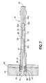
- FIG. 7 is a diagram showing a sectional view of a sensing tip reamer (of the type depicted in FIG. 1 ) which has been shut down in response to the sensing tip impinging on composite material in and at the end of a hole that is slightly short (e.g., 0.050 inch) of being completed.
- FIG. 8 is a hardware block diagram showing components of a system that incorporates a sensing tip reamer of any type disclosed herein.
- FIG. 9 is a logic diagram showing steps of a process for automated shutdown of a reamer if a condition indicating an incomplete hole is detected.
- FIG. 10 is a diagram showing an isometric view of a sensing tip in accordance with another embodiment.
- the system disclosed herein is designed to prevent the running of a reaming operation prior to drilling the necessary pre-hole in CFRP material.
- a reaming technology is provided that will not harm the CFRP structure if a reamer were used out of sequence.
- a reamer having a sensing tip is installed in a powered drill motor that may be powered electrically, by pressurized air or other known means. The system shuts off the drill motor if the tip of the reamer encounters blank material.
- the system employs a control that shuts off the drill motor when a fluid parameter associated with a coolant or lubricant flowing through the reamer is restricted due to depression (relative to the reamer cutting edges) of the sensing tip, which is axially movable relative to the cutting edges of the reamer.
- the coolant or lubricant may comprise a liquid, gas, or mixture of liquid and gas such as a mist coolant or lubricant. Suitable gases may include air, inert gas or refrigerant. Depression of the sensing tip occurs when the tip meets blank material or an obstacle inside an incompletely drilled pre-hole while the cutting portion of the reamer continues to advance.
- the control causes a shutoff valve to close in the case of an air-powered drive or opens a switch in the case of an electric drive, thereby stopping rotation and advancement, or advancement, of the reamer.
- the control may also shut down the metering pumps that provide air/coolant to the reamer. The system inhibits a reaming operation when blank or partially drilled material is encountered.
- FIG. 1 shows an isometric view of a rotary cutting tool in accordance with one embodiment.
- the tool comprises reamer 10 and an integrally formed sensing tip/shaft comprising a sensing tip 16 and a shutoff shaft.
- the shutoff shaft is not visible in FIG. 1 because it is inside the reamer 10 .
- the reamer 10 comprises a hollow body 12 having an internal cavity (not shown in FIG. 1 ) that extends from a forward end to a rearward end along a central axis.
- the reamer 10 further comprises a plurality of teeth 14 extending outwardly to form cutting surfaces near the forward end of hollow body 12 .
- the cutting edges define an outer diameter of the reamer 10 .
- FIG. 2 shows (on a magnified scale) the sensing tip 16 in its most forward position relative to reamer 10 .
- the sensing tip 16 comprises three contact arms 18 disposed radially outward at angles of 120 degrees. If any portion of the sensing tip 16 encounters an obstacle during reaming of a pre-hole, the sensing tip as seen in FIG. 2 will move to the right relative to the cutting teeth 14 .
- the diameter of a hypothetical circle around the contact arms 18 may be in the range of 0.005 to 0.100 inch smaller than the reamer outer diameter.
- the tip 16 is relieved to minimize any impact to chip flow.
- the tip is made of stainless steel.
- FIG. 2 also shows that each flute between cutting teeth 14 is provided with one or more vent holes 4 .
- each flute between cutting teeth 14 is provided with one or more vent holes 4 .
- a jet spray of droplets of coolant suspended in air will flow through an internal cavity of the reamer and exit the reamer via the vent holes 4 , thereby cooling the cutting teeth 14 during the reaming operation.
- the integrally formed sensing tip/shaft is shown removed from the reamer in FIG. 3 .
- the contact arms 18 of sensing tip 16 are machined with a tri-lobed contact surface 20 , each lobe disposed at a 135-degree angle.
- the integrally formed sensing tip/shaft further comprises a shutoff shaft 22 .
- the shutoff shaft 22 comprises a guide body 24 , a plurality of circumferentially distributed, radially projecting guide features 26 and a retention slot 28 .
- FIG. 4 shows an end view as seen from a vantage forward of the sensing tip 16 .
- the guide body 24 has an annular groove that receives a seal such as an O-ring 30 .
- the guide body 24 has an outer diameter greater than the outer diameter of the main portion of the shutoff shaft 22 .
- FIG. 5 is a sectional view showing a sensing tip reamer (of the type depicted in FIG. 1 ) during reaming a completed hole 40 in a stack-up consisting of metal 42 and composite material 44 .
- the sensing tip 16 did not make contact with any obstacle inside completed pre-hole 40 , so the reaming operation did not need to be aborted. In other words, the entire pre-hole 40 was reamed completely.
- FIG. 5 shows the internal structure of the reamer 10 and how shutoff shaft 22 is disposed inside the reamer internal cavity.
- the internal cavity comprises four circular cylindrical bores 32 a through 32 d which increase in diameter from right to left (as seen in FIG. 5 ).
- a jet spray of air and suspended droplets of liquid coolant enters section 32 a of the internal cavity via an opening 50 at the rear end of the hollow body 12 of reamer 10 .
- the air/coolant jet flows through sections 32 a , 32 b and 32 c , exiting the hollow body 12 through the aforementioned vent holes (not shown) between the cutting teeth 14 .
- FIG. 5 shows the internal structure of the reamer 10 and how shutoff shaft 22 is disposed inside the reamer internal cavity.
- the internal cavity comprises four circular cylindrical bores 32 a through 32 d which increase in diameter from right to left (as seen in FIG. 5 ).
- a jet spray of air and suspended droplets of liquid coolant enters section 32 a of the internal cavity via
- the guide features 26 hold the shutoff shaft 22 in a central position inside section 32 c of the internal cavity of reamer 10 .
- the outer diameter of the guide features 26 is greater than the outer diameter of shutoff shaft 22 , creating an annular space between the outer surface of shutoff shaft 22 and the inner surface of section 32 c .
- the air/coolant flows through this annular space on its way to the vent holes (see items 4 in FIG. 2 ) located between the cutting teeth 14 .
- shutoff shaft 22 is inserted into the internal cavity of hollow body 12 and then a set screw 36 is passed through the retention slot 28 in shutoff shaft 22 , the ends of the set screw being threadably coupled in diametrally opposed threaded holes (one such hole 6 can be seen in FIG. 1 ) formed in the wall of the hollow body 12 .
- the set screw 36 retains the shutoff shaft 22 inside the hollow body 12 but, in cooperation with elongated axial slot 28 formed in shutoff shaft 22 , allows the shutoff shaft 22 to move axially between first and second limit positions relative to the hollow body.
- shutoff shaft 22 in the first limit position, further axial movement rearward being stopped by impingement of the rearward end of slot 28 against set screw 36 .
- the sensing tip/shaft 16 is urged into the relative position seen in FIG. 5 by a compression spring 38 which is placed between respective annular surfaces on the guide body 24 and on the hollow body 12 .
- the sensing tip/shaft will remain in the relative position shown in FIG. 5 .
- the rear end 22 a of shutoff shaft 22 does not enter section 32 b of the reamer internal cavity as seen in area 8 .
- the compression spring 38 can be omitted and the shutoff shaft 22 can be pressure biased in the forward direction by the coolant flowing into the internal cavity of the reamer.
- the forces on the shutoff shaft 22 are unbalanced and bias the shaft to the extended position when coolant pressure is present.
- FIG. 6 shows a sectional view of the same sensing tip reamer depicted in FIG. 5 , except that the sensing tip reamer has been inserted in a partially drilled pre-hole 46 (closed at the bottom) in the metal/composite stack-up 42 / 44 .
- the sensing tip/shaft ceases to advance while the reamer 10 continues its advance.
- the sensing tip/shaft moves rearward relative to reamer 10 .
- the end 22 a of shutoff shaft 22 moves axially past position 8 and into section 32 b of the reamer internal cavity.
- the end portion near end 22 a which enters section 32 b has an annular groove in which an O-ring 34 is seated. Because the diameter of section 32 b is less than the diameter of section 32 c , where shutoff end 22 a previously resided, the cross-sectional area of the annular space between the shaft end 22 a and the internal cavity is reduced. In addition, the O-ring 34 further reduces the amount of air/coolant that can flow axially from section 32 b into section 32 c .
- the result of the rearward movement of the shaft into section 32 b of the reamer internal cavity is a reduction in the rate of air/coolant flow through the reamer (accompanied by a pressure increase in the line feeding air/coolant to the reamer).
- the O-ring 34 and the annular groove that it sits in can be omitted and a clearance fit between the rear end 22 a of shutoff shaft 22 and section 32 b can be provide which is capable of causing a suitable reduction in the rate of air/coolant flow through the reamer when rear end 22 a is engaged with section 32 b .
- this reduction in the fluid flow rate (or increase in pressure) is detected by the system.
- the supply of pressurized air to the drill motor is shut off and the reaming operation is automatically aborted.
- FIG. 6 shows the shutoff shaft 22 in a third position relative to the hollow body 12 , which third position is between the first and second limit positions.
- FIG. 7 shows a sectional view of the same sensing tip reamer depicted in FIG. 5 , except that the sensing tip reamer has been inserted in an incompletely drilled pre-hole 46 that is only a small distance (e.g., 0.050 inch) short of a completed hole.
- the sensing tip/shaft again ceases to advance while the reamer 10 continues its advance. The result is that the sensing tip/shaft will again move rearward relative to reamer 10 , eventually aborting the reaming operation.
- FIG. 8 is a block diagram showing components of a system providing the functionality described above.
- the reamer 10 is coupled to a positive feed drill 52 (e.g., a Quackenbush positive feed drill) having a pneumatic motor.
- the pneumatic motor of drill 52 is powered by pressurized air from a plant air source 54 via a solenoid-actuated main air shutoff valve 56 and an air valve 58 [DMFI] .
- the operational state of shutoff valve 56 is controlled by a microcontroller 64 which can activate/deactivate a solenoid to respectively open/close the shutoff valve 56 .
- the microcontroller 64 can be programmed using an external personal computer 66 . When the system is in a locked state (i.e., key switch 68 is open), the system can be activated only by using a key to close key switch 68 .
- the microcontroller When the system is activated, the microcontroller first opens the shutoff valve 56 . Pressurized air flows through shutoff valve 56 to air valve 58 . Some of the air flow (indicated by a line labeled “P ILOT A IR ” in FIG. 8 ) is diverted to an air distribution system that distributes pilot air to solenoid-actuated valves 70 , 72 , 74 and an air pressure sensor 62 . The air pressure sensor 62 outputs a digital signal representing the pilot air pressure to the microcontroller 64 .
- the microcontroller 64 When the pilot air pressure reaches a first specified threshold, the microcontroller 64 is programmed to open valves 70 and 72 , thereby supplying pilot air respective air pulse generators (not shown) which are used to send pulses of air to activate pistons of respective metering pumps (also not shown) that respectively meter motor oil and coolant from respective reservoirs 78 and 80 . If the pilot air pressure reaches a second specified threshold (higher than the first specified threshold and corresponding to a pressure buildup if no air is being supplied to the drill motor), the microcontroller is programmed to open a dump valve 74 to equalize the system.
- a second specified threshold higher than the first specified threshold and corresponding to a pressure buildup if no air is being supplied to the drill motor
- FIG. 8 depicts the delivery of motor oil via a capillary tube (labeled “A IR M OTOR L UBE ” in FIG. 8 ) to an air line 60 connected to air valve 58 .
- the motor oil is metered by a metering pump (not shown in FIG. 8 ) coupled to an outlet of an oil reservoir 78 .
- the metering pump is an adjustable-stroke piston pump.
- pilot air from air valve 58 is provided via open valve 70 to an air pulse generator (not shown) that sends pulses of air to activate the motor oil metering pump.
- sensor 76 is a flow sensor that outputs an analog signal (0 V to 5 V) representing the rate of air flow through the sensor to the microcontroller 64 . (When there is no flow, the output of the sensor is 0 V.)
- sensor 76 is a fluid pressure sensor. The air (labeled “D RILL B IT A IR ” in FIG. 8 ) flowing out of sensor 76 is supplied to the drill bit, i.e., reamer 10 , via an air line 82 .
- lubricant e.g., Micro-cut 26 coolant or Boelube oil
- a capillary tube labeleled “D RILL B IT L UBE ” in FIG. 8
- line 82 which feeds the air and lubricant to the reamer 10 .
- the lubricant (coolant or oil) is supplied to the reamer 10 via a 3 ⁇ 8-inch line for air with a 1 ⁇ 8-inch capillary for lubricant inside.
- the lubricant is Micro-cut 26 coolant.
- the coolant is delivered by a metering pump (not shown in FIG.
- the metering pump is an adjustable-stroke piston pump.
- the valve 72 (under the control of microcontroller 64 ) opens pilot air from air valve 58 to an air pulse generator (not shown) that sends pulses of air to activate the coolant metering pump.
- a pre-hole in a composite/metal stackup can be reamed by the rotating cutting teeth of the advancing reamer 10 .
- the flow sensor output to the microcontroller is monitored to determine if the flow rate of air through the reamer has been sufficiently reduced due to obstruction of the sensing tip.
- the microcontroller is programmed to actuate closure of shutoff valve 56 as well as motor oil and coolant valves 70 and 72 in response to the air flow rate falling below a specified threshold.
- the pressure sensor output to the microcontroller is monitored to determine if the air pressure in the supply line has increased sufficiently due to obstruction of the sensing tip.
- the microcontroller is programmed to actuate closure of shutoff valve 56 as well as motor oil and coolant valves 70 and 72 in response to the air pressure rising above a specified threshold.
- FIG. 9 One implementation of a method of aborting a reaming operation is depicted in the logic diagram of FIG. 9 .
- the motor air supply is turned on (step 84 ).
- the coolant valve 72 is opened.
- Pressurized air (90 psi) and coolant are then supplied to the reamer (step 86 ).
- the air flow rate is measured by the flow sensor, which outputs an analog signal representing the air flow rate to the microcontroller.
- the microcontroller continuously monitors whether the coolant/air flow rate has fallen below 4 cfm (step 88 ). If not, then the main air shutoff valve is not closed (step 90 ).
- the 3-second loop 92 is the time the system takes to detect that a drop in flow has occurred. This is an adjustable setting in the system software.
- the setting should be selected to avoid any momentary events that may trigger a shutoff and still stop the system in time to mitigate any damage to the workpiece to be reamed. If the coolant/air flow rate has fallen below 4 cfm, then the main air shutoff valve is switched from open to closed (step 94 ). The microcontroller then sends a message to a user screen displayed on a personal computer (step 96 ).
- the key switch 68 is a reset feature used after the system encounters an undersize or blank hole condition. It is preferred to keep this functionality away from the reamer operator so that he/she cannot not simply reset the system without removing the drill motor from the drill jig.
- the reset key resides with the drill motor set-up technician. This forces the operator to take a step back from the process to determine why the system tripped.
- a sensing tip 100 is removable and rotatably coupled to one end of a shutoff shaft 98 .
- the rotating sensing tip 100 has two contact arms 18 and comprises a plug 102 having an annular groove.
- the plug 102 of sensing tip 100 is inserted into a socket 104 formed in a guide body 106 at one end of shutoff shaft 98 .
- the plug 102 is coupled to the socket 104 by inserting a slotted spring pin 108 into a radial opening in the socket wall.
- the radially inward end of slotted spring pin 108 sits in the annular groove 102 of the sensing tip 100 .
- This arrangement allows the sensing tip 100 to rotate relative to the shutoff shaft 98 while being coupled for axial movement therewith.
- the shutoff shaft 98 has a plurality of circumferentially distributed, radially projecting guide features 26 and a retention slot 28 .
- the guide body 106 has an annular recess that receives an O-ring 30 .
- the guide body 106 has an outer diameter greater than the outer diameter of the shutoff shaft 98 , providing an annular bearing surface for the spring 38 which urges the shutoff shaft and the reamer in opposite directions.
- a sensing tip arranged to block the flow of an air-coolant mixture to a reamer or drill when confronted by an obstruction is not limited to use with pneumatic drilling systems, but rather could also be incorporated in electrical drilling systems.
- the electrical drilling system instead of closing a shutoff valve, thereby shutting down the drill motor, in response to rearward relative displacement of the sensing tip, the electrical drilling system would simply be shut down by changing the state of an electrical switch.
Landscapes
- Engineering & Computer Science (AREA)
- Mechanical Engineering (AREA)
- Drilling And Boring (AREA)
Abstract
Description
Claims (14)
Priority Applications (1)
| Application Number | Priority Date | Filing Date | Title |
|---|---|---|---|
| US13/477,139 US9095947B1 (en) | 2012-05-22 | 2012-05-22 | Sensing tip reamer |
Applications Claiming Priority (1)
| Application Number | Priority Date | Filing Date | Title |
|---|---|---|---|
| US13/477,139 US9095947B1 (en) | 2012-05-22 | 2012-05-22 | Sensing tip reamer |
Publications (1)
| Publication Number | Publication Date |
|---|---|
| US9095947B1 true US9095947B1 (en) | 2015-08-04 |
Family
ID=53718809
Family Applications (1)
| Application Number | Title | Priority Date | Filing Date |
|---|---|---|---|
| US13/477,139 Expired - Fee Related US9095947B1 (en) | 2012-05-22 | 2012-05-22 | Sensing tip reamer |
Country Status (1)
| Country | Link |
|---|---|
| US (1) | US9095947B1 (en) |
Cited By (1)
| Publication number | Priority date | Publication date | Assignee | Title |
|---|---|---|---|---|
| US20150260634A1 (en) * | 2014-03-11 | 2015-09-17 | The Boeing Company | Apparatuses and methods for testing adhesion of a seal to a surface |
Citations (21)
| Publication number | Priority date | Publication date | Assignee | Title |
|---|---|---|---|---|
| US76188A (en) * | 1868-03-31 | Improved earth-boring auger | ||
| US1561463A (en) * | 1924-03-18 | 1925-11-17 | Rochemont Allen C De | Counterbore |
| US1598655A (en) | 1924-09-15 | 1926-09-07 | Waterbury Farrel Foundry Co | Drilling machine |
| US1985356A (en) * | 1931-10-12 | 1934-12-25 | Cleef Brothers Van | Cutting apparatus |
| US2224480A (en) * | 1939-10-27 | 1940-12-10 | Kartarik Joseph | Centering device |
| US2484150A (en) * | 1946-12-10 | 1949-10-11 | Brown Robert Lee | Work-expelling device for tubular saws |
| US3381550A (en) | 1965-06-07 | 1968-05-07 | Theodore M. Smith | Apparatus for a tool failure detection system |
| US3973858A (en) | 1974-06-14 | 1976-08-10 | Regie Nationale Des Usines Renault | Pneumatic control device for terminating the machining operation of a spindle machine |
| US4056329A (en) | 1976-03-08 | 1977-11-01 | Invo Spline, Inc. | Detection system for machine tools |
| US4180356A (en) | 1978-08-03 | 1979-12-25 | Hoch Norman J | Broken tool detector |
| US4507025A (en) | 1983-06-07 | 1985-03-26 | Masco Machine Incorporated | Combined torque and thrust overload responsive tool holder |
| SU1199473A1 (en) * | 1983-05-26 | 1985-12-23 | Кубанский Ордена Трудового Красного Знамени Сельскохозяйственный Институт | Boring head |
| US4579487A (en) * | 1984-09-17 | 1986-04-01 | Lehmkuhl Robert A | Tool adapter |
| US4720218A (en) | 1987-05-01 | 1988-01-19 | The Boeing Company | Combination drilling and dressing bit |
| SU1386377A1 (en) * | 1986-08-27 | 1988-04-07 | Волжское Объединение По Производству Легковых Автомобилей Им.50-Летия Ссср | Boring mandrel |
| US4751652A (en) | 1983-02-03 | 1988-06-14 | Fanuc Ltd. | Numerical control drilling restart control system |
| US5000630A (en) | 1989-01-17 | 1991-03-19 | The Boeing Company | Bit for forming holes in composite materials |
| US5171111A (en) * | 1991-07-05 | 1992-12-15 | Kansai Kogu Manufacturing Co., Ltd. | Drilling tool |
| US5316418A (en) * | 1992-09-21 | 1994-05-31 | Kabushiki Kaisha Miyanaga | Hole cutter |
| US6250856B1 (en) * | 1997-02-28 | 2001-06-26 | Kabushiki Kaisha Miyanaga | Quick attachment structure for drill shank |
| US20090129877A1 (en) | 2007-11-19 | 2009-05-21 | Brady Steven K | Systems and methods for material interface detection during drilling operations |
-
2012
- 2012-05-22 US US13/477,139 patent/US9095947B1/en not_active Expired - Fee Related
Patent Citations (21)
| Publication number | Priority date | Publication date | Assignee | Title |
|---|---|---|---|---|
| US76188A (en) * | 1868-03-31 | Improved earth-boring auger | ||
| US1561463A (en) * | 1924-03-18 | 1925-11-17 | Rochemont Allen C De | Counterbore |
| US1598655A (en) | 1924-09-15 | 1926-09-07 | Waterbury Farrel Foundry Co | Drilling machine |
| US1985356A (en) * | 1931-10-12 | 1934-12-25 | Cleef Brothers Van | Cutting apparatus |
| US2224480A (en) * | 1939-10-27 | 1940-12-10 | Kartarik Joseph | Centering device |
| US2484150A (en) * | 1946-12-10 | 1949-10-11 | Brown Robert Lee | Work-expelling device for tubular saws |
| US3381550A (en) | 1965-06-07 | 1968-05-07 | Theodore M. Smith | Apparatus for a tool failure detection system |
| US3973858A (en) | 1974-06-14 | 1976-08-10 | Regie Nationale Des Usines Renault | Pneumatic control device for terminating the machining operation of a spindle machine |
| US4056329A (en) | 1976-03-08 | 1977-11-01 | Invo Spline, Inc. | Detection system for machine tools |
| US4180356A (en) | 1978-08-03 | 1979-12-25 | Hoch Norman J | Broken tool detector |
| US4751652A (en) | 1983-02-03 | 1988-06-14 | Fanuc Ltd. | Numerical control drilling restart control system |
| SU1199473A1 (en) * | 1983-05-26 | 1985-12-23 | Кубанский Ордена Трудового Красного Знамени Сельскохозяйственный Институт | Boring head |
| US4507025A (en) | 1983-06-07 | 1985-03-26 | Masco Machine Incorporated | Combined torque and thrust overload responsive tool holder |
| US4579487A (en) * | 1984-09-17 | 1986-04-01 | Lehmkuhl Robert A | Tool adapter |
| SU1386377A1 (en) * | 1986-08-27 | 1988-04-07 | Волжское Объединение По Производству Легковых Автомобилей Им.50-Летия Ссср | Boring mandrel |
| US4720218A (en) | 1987-05-01 | 1988-01-19 | The Boeing Company | Combination drilling and dressing bit |
| US5000630A (en) | 1989-01-17 | 1991-03-19 | The Boeing Company | Bit for forming holes in composite materials |
| US5171111A (en) * | 1991-07-05 | 1992-12-15 | Kansai Kogu Manufacturing Co., Ltd. | Drilling tool |
| US5316418A (en) * | 1992-09-21 | 1994-05-31 | Kabushiki Kaisha Miyanaga | Hole cutter |
| US6250856B1 (en) * | 1997-02-28 | 2001-06-26 | Kabushiki Kaisha Miyanaga | Quick attachment structure for drill shank |
| US20090129877A1 (en) | 2007-11-19 | 2009-05-21 | Brady Steven K | Systems and methods for material interface detection during drilling operations |
Cited By (2)
| Publication number | Priority date | Publication date | Assignee | Title |
|---|---|---|---|---|
| US20150260634A1 (en) * | 2014-03-11 | 2015-09-17 | The Boeing Company | Apparatuses and methods for testing adhesion of a seal to a surface |
| US9404848B2 (en) * | 2014-03-11 | 2016-08-02 | The Boeing Company | Apparatuses and methods for testing adhesion of a seal to a surface |
Similar Documents
| Publication | Publication Date | Title |
|---|---|---|
| KR102370953B1 (en) | Tire mold drilling work platform, machine tool and tire mold exhaust hole processing method | |
| US10583500B2 (en) | Multi-functional end effector | |
| EP1884313B1 (en) | Apparatus and method for working a work piece, such as a shell structure for an aircraft | |
| US9061389B2 (en) | Working unit | |
| CN105228793B (en) | Force-feed tool with replaceable gears for adjusting feed rate | |
| US8939685B2 (en) | Cutting tool | |
| US20090214307A1 (en) | High speed hand drill with swiveling pressure foot and integrated vacuum pickup and coolant delivery duct | |
| EP2839924B1 (en) | Fluid-fed vacuum cutters | |
| JP5292045B2 (en) | Deep hole cutting equipment | |
| US8585332B2 (en) | Linear compensator tool for drill countersinking and seal groove machining | |
| CN112166008B (en) | Abrasive fluid jet cutting systems, components, and related methods for cutting sensitive materials | |
| US20130192331A1 (en) | Installation/processing systems, methods, and components | |
| JP2002321111A (en) | Deep hole drilling apparatus | |
| US9095947B1 (en) | Sensing tip reamer | |
| US9114492B2 (en) | Coolant supply for a machine tool | |
| US5927910A (en) | Automated drilling apparatus | |
| US3546976A (en) | Power operated drill | |
| JP7030003B2 (en) | Rotary joint and fluid feeding mechanism | |
| CN107020404B (en) | Countersinking apparatus and related method | |
| EP0584412A1 (en) | Precision depth spindle | |
| CN206066026U (en) | Award gas formula drilling tool system of connections | |
| KR200462434Y1 (en) | Automatic control device of oil flow generation oil mist | |
| CN207014116U (en) | Cooling handle of a knife for mist of oil injection milling | |
| JP6588205B2 (en) | Tool driving device and method for manufacturing punched product | |
| CN107363632A (en) | A kind of mist of oil sprays the automatic with Target process of milling |
Legal Events
| Date | Code | Title | Description |
|---|---|---|---|
| AS | Assignment |
Owner name: THE BOEING COMPANY, ILLINOIS Free format text: ASSIGNMENT OF ASSIGNORS INTEREST;ASSIGNORS:DELAND, JAMES A.;KESTERSON, MATTHEW G.;REEL/FRAME:028245/0276 Effective date: 20120521 |
|
| FEPP | Fee payment procedure |
Free format text: PAYOR NUMBER ASSIGNED (ORIGINAL EVENT CODE: ASPN); ENTITY STATUS OF PATENT OWNER: LARGE ENTITY |
|
| STCF | Information on status: patent grant |
Free format text: PATENTED CASE |
|
| MAFP | Maintenance fee payment |
Free format text: PAYMENT OF MAINTENANCE FEE, 4TH YEAR, LARGE ENTITY (ORIGINAL EVENT CODE: M1551); ENTITY STATUS OF PATENT OWNER: LARGE ENTITY Year of fee payment: 4 |
|
| FEPP | Fee payment procedure |
Free format text: MAINTENANCE FEE REMINDER MAILED (ORIGINAL EVENT CODE: REM.); ENTITY STATUS OF PATENT OWNER: LARGE ENTITY |
|
| LAPS | Lapse for failure to pay maintenance fees |
Free format text: PATENT EXPIRED FOR FAILURE TO PAY MAINTENANCE FEES (ORIGINAL EVENT CODE: EXP.); ENTITY STATUS OF PATENT OWNER: LARGE ENTITY |
|
| STCH | Information on status: patent discontinuation |
Free format text: PATENT EXPIRED DUE TO NONPAYMENT OF MAINTENANCE FEES UNDER 37 CFR 1.362 |
|
| FP | Lapsed due to failure to pay maintenance fee |
Effective date: 20230804 |