US9095203B2 - Unitary composite backpack frame with upper stays - Google Patents
Unitary composite backpack frame with upper stays Download PDFInfo
- Publication number
- US9095203B2 US9095203B2 US13/856,594 US201313856594A US9095203B2 US 9095203 B2 US9095203 B2 US 9095203B2 US 201313856594 A US201313856594 A US 201313856594A US 9095203 B2 US9095203 B2 US 9095203B2
- Authority
- US
- United States
- Prior art keywords
- backpack frame
- frame
- backpack
- upper portion
- shaped tongue
- Prior art date
- Legal status (The legal status is an assumption and is not a legal conclusion. Google has not performed a legal analysis and makes no representation as to the accuracy of the status listed.)
- Active
Links
Images


Classifications
-
- A—HUMAN NECESSITIES
- A45—HAND OR TRAVELLING ARTICLES
- A45F—TRAVELLING OR CAMP EQUIPMENT: SACKS OR PACKS CARRIED ON THE BODY
- A45F3/00—Travelling or camp articles; Sacks or packs carried on the body
- A45F3/04—Sacks or packs carried on the body by means of two straps passing over the two shoulders
- A45F3/08—Carrying-frames; Frames combined with sacks
-
- A—HUMAN NECESSITIES
- A45—HAND OR TRAVELLING ARTICLES
- A45C—PURSES; LUGGAGE; HAND CARRIED BAGS
- A45C13/00—Details; Accessories
- A45C13/04—Frames
-
- A—HUMAN NECESSITIES
- A45—HAND OR TRAVELLING ARTICLES
- A45F—TRAVELLING OR CAMP EQUIPMENT: SACKS OR PACKS CARRIED ON THE BODY
- A45F3/00—Travelling or camp articles; Sacks or packs carried on the body
- A45F3/04—Sacks or packs carried on the body by means of two straps passing over the two shoulders
- A45F3/047—Sacks or packs carried on the body by means of two straps passing over the two shoulders with adjustable fastenings for the shoulder straps or waist belts
-
- A—HUMAN NECESSITIES
- A45—HAND OR TRAVELLING ARTICLES
- A45F—TRAVELLING OR CAMP EQUIPMENT: SACKS OR PACKS CARRIED ON THE BODY
- A45F3/00—Travelling or camp articles; Sacks or packs carried on the body
- A45F3/10—Pack-frames carried on the body
-
- A—HUMAN NECESSITIES
- A45—HAND OR TRAVELLING ARTICLES
- A45F—TRAVELLING OR CAMP EQUIPMENT: SACKS OR PACKS CARRIED ON THE BODY
- A45F3/00—Travelling or camp articles; Sacks or packs carried on the body
- A45F3/12—Shoulder-pads
-
- B—PERFORMING OPERATIONS; TRANSPORTING
- B32—LAYERED PRODUCTS
- B32B—LAYERED PRODUCTS, i.e. PRODUCTS BUILT-UP OF STRATA OF FLAT OR NON-FLAT, e.g. CELLULAR OR HONEYCOMB, FORM
- B32B37/00—Methods or apparatus for laminating, e.g. by curing or by ultrasonic bonding
- B32B37/14—Methods or apparatus for laminating, e.g. by curing or by ultrasonic bonding characterised by the properties of the layers
-
- A—HUMAN NECESSITIES
- A45—HAND OR TRAVELLING ARTICLES
- A45F—TRAVELLING OR CAMP EQUIPMENT: SACKS OR PACKS CARRIED ON THE BODY
- A45F3/00—Travelling or camp articles; Sacks or packs carried on the body
- A45F3/04—Sacks or packs carried on the body by means of two straps passing over the two shoulders
- A45F2003/045—Sacks or packs carried on the body by means of two straps passing over the two shoulders and one additional strap around the waist
-
- A—HUMAN NECESSITIES
- A45—HAND OR TRAVELLING ARTICLES
- A45F—TRAVELLING OR CAMP EQUIPMENT: SACKS OR PACKS CARRIED ON THE BODY
- A45F3/00—Travelling or camp articles; Sacks or packs carried on the body
- A45F3/12—Shoulder-pads
- A45F2003/122—Back cushioning parts or details of backpacks, e.g. with ventilation
- A45F2003/125—Back cushioning parts or details of backpacks, e.g. with ventilation with ventilation
-
- A—HUMAN NECESSITIES
- A45—HAND OR TRAVELLING ARTICLES
- A45F—TRAVELLING OR CAMP EQUIPMENT: SACKS OR PACKS CARRIED ON THE BODY
- A45F3/00—Travelling or camp articles; Sacks or packs carried on the body
- A45F3/12—Shoulder-pads
- A45F2003/127—Dorsal or hip pads for the lumbar back or for the waist
Definitions
- the invention relates to frames for backpacks and knapsacks and to methods of making those frames.
- Backpack frames may be either internal to the backpack or external to it.
- external backpack frames have been made of metal tubes, such as aluminum or steel tubes. These types of frames are simple to construct, as the tubes are simply welded together, but they are typically very heavy, and thus reduce the effective load that a user can carry.
- Internal backpack frames are generally made to be lighter, but problems typically arise in making an internal frame that has a useful combination of strength and flexibility. Some degree of flexibility in a backpack frame can help to cushion the user against shifts in the load as he or she walks or runs and to “decouple” the backpack load from the user and his or her movements. However, the problem is multifaceted, because there are some places in a backpack frame where strength and stiffness are warranted in order to properly support the backpack load.
- the backpack frames are of sandwich construction, with upper and lower layers of a fiber material and a selectively placed reinforcing layer.
- the frames have an upper portion with upwardly extending, elongate stays that support and decouple the load of the backpack from the wearer.
- the upper portion also includes a pair of generally vertically oriented open tracks that provide for sliding, positionable attachment of backpack shoulder strap assemblies.
- the lower portion curves to follow the typical lumbar-sacral curvature of the human back and terminates in a generally U-shaped tongue. Openings and unreinforced areas may be provided in the frame to lighten the frame and provide for selective flexibility.
- Frames according to this aspect of the invention may be made by a number of methods, including compression molding.
- FIG. 1 is a perspective view of a backpack and frame according to one embodiment of the invention
- FIG. 2 is a perspective view of the backpack frame of FIG. 1 with straps and without the backpack;
- FIG. 3 is a front perspective view of the backpack frame of FIGS. 1-2 in isolation;
- FIG. 4 is a rear perspective view of the backpack frame of FIG. 1 ;
- FIG. 5 is a side elevational view of the backpack frame of FIG. 1 ;
- FIG. 6 is a front elevational view of the backpack frame of FIG. 1 with a hip strap attachment installed;
- FIG. 7 is a rear elevational view of the backpack frame of FIG. 1 shaded to indicate the position and extent of reinforcing layers within the frame;
- FIG. 8 is a rear elevational view of a backpack frame according to another embodiment of the invention, shaded to indicate the position and extent of reinforcing layers within the frame;
- FIG. 9 is a high-level flow diagram of a method for making a backpack frame
- FIG. 10 is an exploded perspective view of a mold for a backpack frame, illustrating how the components are placed into the mold
- FIG. 11 is a perspective view of a backpack frame according to another embodiment of the invention.
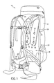
- FIG. 12 is a side elevational view of the backpack frame of FIG. 11 .
- FIG. 1 is a rear perspective view of a backpack, generally indicated at 10 , according to one embodiment of the invention.
- the backpack has a closeable storage volume 12 and a semi-internal frame, generally indicated at 14 .
- semi-internal refers to the fact that in the illustrated embodiment, the frame 14 is at least partially exposed. However, the frame 14 need not necessarily be partially exposed in all embodiments, and may be completely internal.
- the backpack 10 also includes three main load transfer points, or nodes, at which the load of the backpack 10 is transferred to the wearer of the backpack 10 : two independently adjustable and positionable shoulder strap assemblies 16 , 18 and a belt assembly 20 .
- the shoulder strap assemblies 16 , 18 and belt assembly 20 attach to the frame 14 using fasteners 22 , 24 .
- the shoulder strap assemblies 16 , 18 attach to the frame 14 along respective sliding tracks, so that their vertical and horizontal positions can be independently adjusted.
- the fastener 24 (not shown in FIG. 1 ) and related structure that secure the belt assembly 20 to the frame 14 are such that the belt assembly 20 can rotate in plane about the axis defined by the fastener 24 .
- FIG. 2 is a perspective view of the frame 14 with the shoulder strap assemblies 16 , 18 and belt assembly 20 installed, but without the backpack 10 .
- Straps 26 , 28 , 29 attached to the shoulder strap and belt assemblies 16 , 18 , 20 are looped through slots 32 , 34 , 36 in the frame 14 to connect the assemblies 16 , 18 , 20 to the frame 14 , as will be described below in more detail.
- Each of the assemblies 16 , 18 , 20 includes a padded portion 38 , 40 that is adapted to rest against the body.
- Straps 26 , 28 typically made of webbing, such as nylon webbing, are attached to the padded portion. Length adjustment buckles and quick-release connectors are provided to fit the assemblies 16 , 18 , 20 to the body.
- FIG. 3 is a front perspective view of the frame 14 in isolation.
- the frame 14 is most advantageously a unitary (i.e., single piece) structure that is engineered for flexibility in some places and stiffness in others.
- the frame 14 includes a pair of left and right stay portions 42 , 44 , a mid-back portion 46 , and a lower portion 48 , which attaches to the belt assembly 20 .
- left and right refer only to the coordinate system of the figures.
- the left and right stay portions 42 , 44 are mirror images of one another, and are the primary means by which the frame 14 connects to and suspends the load of the backpack 10 .
- the respective top and bottom ends of the stay portions 42 , 44 fit into correspondingly positioned and sized pockets in the backpack 10 (not shown in the figures).
- the stay portions 42 , 44 provide the combination of flexibility and selective strength that suspends the load in the backpack 10 while mechanically decoupling and cushioning it from the wearer.
- the contours of the stay portions 42 , 44 are designed to bring the load from the load transfer points, follow generally the curvature of the human back, and provide clearance where necessary so that, for example, an elbow projected rearwardly during stride will not hit the frame 14 .
- the static contours of the stay portions 42 , 44 help to pretension the stay portions 42 , 44 so that in dynamic use, with the backpack 10 loaded, they can store and release energy, increasing their ability to cushion and decouple the load from the wearer.
- the stay portions 42 , 44 act as resilient members or springs to suspend the load.
- the stay portions 42 , 44 curve in at least two planes.
- the two stay portions 42 , 44 begin generally parallel to one another toward the top of the frame, extending a few inches above the mid-back portion 46 .
- the two stay portions 42 , 44 diverge arcuately outwardly until, at their lower terminus, they are separated from the lower portion 48 by a distance and are angled away from the mid-back and lower portions 46 , 48 of the frame.
- stay portions 42 , 44 extend downwardly and diverge to the left and right of the frame 14 , they also curve slightly rearwardly, out of the plane of the frame 14 itself. Because the stay portions 42 , 44 will generally be pulled forwardly during use, the slight rearward curvature of the stay portions 42 , 44 when unloaded causes them to be pretensioned while in dynamic use. Similarly, since the lower ends of the stay members 42 , 44 will typically be drawn laterally inward toward the frame 14 , particularly if they are attached to or near the belt assembly 20 , the left and right divergent curvature of the stay portions 42 , 44 causes them to be pretensioned in that plane as they are drawn inward.
- the top ends of the stay portions 42 , 44 also serve to lift the load slightly off the shoulders and to tension the frame 14 .
- the respective ends of the stay portions 42 , 44 are provided with horizontal and/or vertical slots 32 , 34 , or any other suitable kind of opening or structure, to facilitate connection and engagement with the backpack 10 .
- the mid-back portion 46 may also be provided with attachment slots 50 along its upper edge.
- the mid-back portion 46 of the frame 14 carries a pair of generally linear openings 52 , 54 that serve as tracks in which the fasteners 22 can slide, so as to allow the shoulder strap assemblies 16 , 18 to be independently positioned.
- the openings that serve as tracks 52 , 54 are angled slightly inwardly as they extend from top to bottom, although this need not be the case in all embodiments.
- the openings 52 , 54 may be given any appropriate shape, including curved or arcuate, so as to provide for a range of shoulder strap assembly 16 , 18 positions.
- some embodiments of the frame 14 may be provided with sets or series of unconnected, discrete openings that provide discrete positions into which the shoulder strap assemblies 16 , 18 may be secured.
- the mid-back and lower portions 46 , 48 of the frame 14 carry two large openings 56 , 58 . These openings 56 , 58 provide ventilation and air flow, and also serve to lighten the frame 14 .
- the lower portion 48 of the frame 14 has the general U-shape of a tongue.
- a projection 60 in the form of a truncated cone, projects forwardly, out of the plane of the frame 14 , is provided for attachment of the belt assembly 20 , and includes its own opening 62 to facilitate the passage of fasteners and the securement of the belt assembly 20 .
- the space 64 between the lower end of the track-openings 52 , 54 and the lower of the two large openings 58 acts as a de facto hinge portion, allowing the lower portion 48 to flex somewhat relative to the mid-back portion.
- the mid-back and lower portions 46 , 48 are generally contoured to follow the curvature of the human back.
- the frame 14 may be made of a number of materials, including plastics, but is most advantageously made of composite-type, resin-impregnated materials.
- the frame 14 is made primarily of layers of resin-impregnated carbon fiber sheeting, with selective reinforcement by including interstitial materials between adjacent layers of carbon fiber so as to selectively create sandwich-type composites in areas of the frame requiring more strength or flexibility.
- the layers of carbon fiber may be comprised of, for example, sheets of 284 twill carbon fiber sheeting, and high wear areas, such as the area around the opening 62 in the projection 60 may include additional layers of carbon fiber sheeting.
- An advantage of such composite materials is that they have the capacity to dynamically store and controllably release more energy as they flex than pure plastics or metals would, which may allow them to cushion and decouple the load from the wearer more effectively than other materials.
- FIG. 7 is a rear elevational view of the frame 14 that is shaded to illustrate the location of reinforcements. More specifically, the stippled shading in FIG. 7 illustrates the location and extent of reinforcing material.
- a reinforced area is reinforced with at least one layer of reinforcing material, such as FIBERGLAS®, between inner and outer layers of primary material.
- the stays 42 , 44 have reinforcements 66 , 68 along substantially the entirety of their length, terminating just before the ends of the stays 42 , 44 .
- the reinforcement may comprise sheets of woven or non-woven glass fiber (such as FIBERGLAS®).
- the reinforcements 66 , 68 in the stays 42 , 44 comprise oriented strands of glass yarn or fiber, laid along the long axis of the stays 42 , 44 , as indicated by arrows A in FIG. 7 .
- the reinforcements 66 , 68 in the stays 42 , 44 may comprise foam, as will be described below in more detail.
- a broad section of the frame 14 that extends from the mid-back portion 46 into the lower-back portion 48 is reinforced by the inclusion of a foam insert 70 between two layers of carbon fiber sheeting, creating a sandwich-type composite material.
- the foam insert 70 covers the area around the large opening 56 and the two track-openings 52 , 54 in the mid-back portion 46 and extends downwardly in a horseshoe-shape into the lower portion 48 .
- the foam may be, for example, a PVC closed cell foam.
- the frame 14 may be made by any known method of resin-impregnation.
- One particularly advantageous manufacturing method is resin extrusion, in which sheets of material are cut to desired shapes, laid in a mold, and resin is pumped into and drawn out of the mold.
- the resin used in the manufacture of the frame 14 may be any resin known in the art.
- polyester and epoxy resins may be used in embodiments of the invention, although polyester resins may be more UV-stable over time, and may thus be preferred in some embodiments.
- a completed frame 14 may be, for example, on the order of 0.375 inches thick to about 0.625 inches thick, depending on the desired stiffness and the loads that are to be carried.
- the frame 14 may vary somewhat in thickness across its area, with reinforced areas being thicker.
- the frame 14 as a whole may be thicker if greater strength and/or stiffness are required.
- the size and proportions of the frame 14 will generally be dictated by anthropometric data and ergonomic considerations.
- Backpacks 10 and their frames 14 may be made in a variety of sizes, based on the same or different proportions.
- Frames according to embodiments of the invention may also include additional features.
- a frame may include portions that extend perpendicularly outward from the mid-back or lower back portions and can be used to cinch gear to the frame.
- FIG. 8 is a rear elevational view of a frame 100 according to another aspect of the invention, shaded similarly to FIG. 7 to illustrate the locations of reinforcements.
- Frame 100 is substantially similar to frame 14 , and thus, the description above will suffice for most elements.
- Frame 100 differs from frame 14 of FIGS. 1-7 in the location and extent of its reinforcements and in the size and shape of certain openings.
- frame 100 has separate reinforcements 102 , 104 in the mid-back and lower portions 106 , 108 .
- the reinforcements 102 , 104 may be of the same material or different materials, and may be the same material as used in frame 14 of FIGS. 1-7 .
- the tracks 116 , 118 are also slightly different in shape, as they have lower ends 120 , 122 that broaden into generally rectangular openings.
- frames according to embodiments of the invention may have many different types, shapes, and sizes of openings.
- backpack frames according to embodiments of the invention may be made using a number of different techniques, including vacuum infusion of resin.
- one particularly useful molding method for backpack frames 14 , 100 according to embodiments of the invention is compression molding.
- compression molding fibers and reinforcements are cut to shape and laid in a mold. The laid-out pieces are coated with resin, and the coated assembly is heated for a specified time under pressure to cause the resin to impregnate and bind the layers of material together.
- compression molding processes allow the molded article to have both front and back sides with features and dimensionality.
- FIG. 9 is a high-level flow diagram of a method for compression molding a backpack frame, generally indicated at 200 , according to one embodiment of the invention.
- the backpack frames made using method 200 may have the general shape and characteristics of the backpack frames 14 , 100 described above.
- the materials used in method 200 to make backpack frames may vary from embodiment to embodiment, and the orientation, thickness, and proportions of those materials may be varied to selectively increase the strength and stiffness of the frames 14 , 100 in particular areas.
- Method 200 begins at task 202 and continues with task 204 .
- the materials of which the backpack frames 14 , 100 are made are typically provided in roll and sheet form.
- carbon fiber may be provided in roll form as a woven textile, and foam or PVC reinforcements, if used, may be provided in sheet form.
- the carbon fiber may be, for example, in the form of a textile sheet with a 2 ⁇ 2 twill pattern and 12,000 carbon filaments per strand.
- the layers of material are cut to their proper shapes. In some cases, the materials may be rough-cut and trimmed to their final shapes later, but the shape and profile changes of the backpack frames 14 , 100 make it advantageous to cut the materials so that they are as close to their final shapes as possible early in the process. Once the materials have all been cut to shape, method 200 continues with task 206 .
- FIG. 10 is an exploded perspective view illustrating a suitable mold 250 , including a first mold portion 252 and a second mold portion 254 .
- the first mold portion 252 has a mold cavity 256 of appropriate shape and dimensions to mold one of the backpack frames 14 , 100 .
- the second mold portion 254 has a slight positive boss, not shown in FIG. 10 , that matches the shape and contours of the negative mold cavity 256 .
- the first and second mold portions 252 , 254 may be made of a metal such as aluminum or steel.
- Laying the cut parts in the mold, as in task 206 typically involves laying out and arranging several layers of materials.
- Front and back (alternatively, bottom and top) layers of carbon fiber weave 258 , 260 define the two main faces of the backpack frames 14 , 100 .
- a variety of materials may be interposed between the two layers of carbon fiber fabric as reinforcements 262 .
- the stay reinforcements 66 , 68 described above may comprise four layers of carbon fiber material, oriented as described above.
- the parts are covered with resin. This may be done by brushing, rolling, spraying, or any other means known in the art.
- resin may be used, although vinyl ester resins may also be suitable in some embodiments. Resins with high elongation may be useful, because they may provide more flexibility to the overall structure.
- the resin may be PRO-SET® laminating resin no. 145, coupled with hardener no. 229 (Pro Set Inc., Bay City, Mich., United States).
- the amount of resin that is applied to the parts may vary from embodiment to embodiment; however, a final volume fraction of fiber to resin is preferably about 60% fiber to 30% resin.
- Functional backpack frames 14 , 100 may be achieved with different volume fractions—for example, a backpack frame 14 , 100 may be made that comprises about 70% resin to about 30% fiber. However, backpack frames 14 , 100 with more resin than fiber may need to be heavier and thicker to achieve the same strength.
- method 200 continues with task 210 , in which the two portions 252 , 254 of the mold 250 are engaged. Although not shown in FIG. 10 , the two mold portions 252 , 254 are usually engaged together while resting in a load frame, and a hydraulic cylinder, screw-driven mechanism, or other type of pressure-applying device is used to apply pressure to one or both of the mold portions 252 , 254 . Method 200 continues with task 212 .
- a predefined level of pressure and a predefined temperature are applied for a predefined time.
- the pressure is generally constant throughout the predefined time, while the temperature may be either constant or defined by a function (i.e., the temperature may be ramped up and down in a predefined way).
- the temperatures, pressures, time durations, and, if used, ramping functions may vary widely, depending on the nature of the resin that is used, the desired appearance of the final product, and other factors that are known in the art. For example, in general, the present inventors have found that the less pressure that is used, the better the aesthetic appearance of the finished backpack frame 14 , 100 , while greater pressures lead to lighter parts as some of the resin is squeezed out during the process.
- pressures as low as about 5 tons (4.5 metric tons) may be suitable for some embodiments, 10-12 tons (9-11 metric tons) may be used in other embodiments, and pressures as high as the mold portions 252 , 254 themselves can tolerate may be used in yet other embodiments (e.g., 20-30 tons).
- any temperature that will cure the resin within a reasonable time frame may be used in method 200 . Temperatures in the range of about 100° F. (about 38° C.) to about 200° F. (about 93° C.) may all be suitable in different embodiments, with 150° F. (about 65° C.), and 180° F. (about 82° C.) being common maximum temperatures. Of course, if ramps are used, the mean temperature to which the parts are exposed may be about 125° F. (about 52° C.) or 140° F. (about 60° C.) in those cases. The precise temperature that is used in any implementation of method 200 will depend on the resin that is being used, the pressure, the time, and on other factors known in the art.
- task 212 may involve applying about 11 tons of pressure (10 metric tons) for a period of about two hours while the temperature is ramped from 100° F. to 150° F. (taking about 1 hour) and back down to 100° F. (taking about 1 hour), with only a few minutes of loiter time at the maximum temperature.
- the cool-down period may be shortened, so that a 45-minute ramp-down/cool-down is used before the next set of materials is inserted and method 200 is repeated. A shortened ramp-up of about 45 minutes may also be used.
- the goal of task 212 of method 200 is to bind the materials 258 , 260 , 262 into a unitary structure with composite mechanical properties. Any conditions that achieve that goal may be used in task 212 .
- Heating blankets, resistive heating elements in the mold portions 252 , 254 , a heated chamber, or other known heating means may be used to heat the mold 250 , and those heating elements may be controlled by a standard process controller.
- the molded piece may be trimmed, if necessary, to its final shape before method 200 completes and returns at task 218 .
- the frames 14 , 100 described above include both upper and lower stay portions on a unitary frame.
- different backpacks may require different types of frames, and different types of frames may be made according to embodiments of the invention.
- FIG. 11 is a perspective view of a frame, generally indicated at 300 , according to another embodiment of the invention.
- frame 300 is a unitary frame made of a sandwich composite material.
- frame 300 may be made using two layers of a 3 k 2 ⁇ 2 twill carbon fiber with 1/16 inch core material. It may be made using the compression molding methods, like method 200 , that are described above, although in other embodiments, other techniques, like vacuum impregnation may be used.
- frame 300 may have a thickness of about 0.12 to 0.15 inches.
- frame 300 is symmetrical about its long axis and includes an upper portion 302 that tapers into a lower portion 304 , such that the top of the frame is wider than its bottom.
- Left and right stay upper portions 306 , 308 extend from the top portion 302 .
- frame 300 differs in that it includes only upper stay portions 306 , 308 ; there are no lower stay portions.
- upper stay portions 306 , 308 alone may be enough to suspend the load of a backpack and to decouple the load from the body.
- frame 300 may be used with any type of backpack, its shape may be particularly useful with smaller, lighter day packs.
- the two upper stay portions 306 , 308 diverge outwardly from the centerline of the frame. In one embodiment, there may be about a 10° angle between the two stays 306 , 308 .
- the upper portion 302 includes two open sliding tracks 310 where shoulder strap assemblies may be attached.
- a central opening 312 between the two tracks 310 lightens the frame 300 .
- an unreinforced area 314 provides for greater flexibility.
- the lower portion 304 is open and U-shaped, much like the lower portions of the other frames 14 , 100 .
- frame 300 On its top, sides, and on the tops of the stay portions 306 , 308 , frame 300 includes a number of openings 316 that permit attachment to a backpack or attachment of accessories.
- FIG. 12 is a side elevational view of the frame 300 of FIG. 11 .
- the lower portion 304 is curved to match the lumbar-sacral curve of the back.
- the top portion 302 is more linear than in other embodiments 14 , 100 .
- the stay portions 306 , 308 diverge slightly rearwardly.
- the frame 300 may have a length of approximately 24.5 inches overall, with a width at the bottom of approximately 5 inches and a width at the top, between the centers of the stay portions 306 , 308 of approximately 8.25 inches.
- the stay portions 306 , 308 may extend approximately 7.5 inches.
- a backpack may be coupled to the frame 300 in essentially the same way that the backpack 10 is coupled to its frame 14 .
- the frame 300 does not include structure to attach a rotatable waist belt assembly, as do the frames 14 , 100 described above. If desired, though, a non-rotatable waist belt assembly could be attached using the openings 316 on the sides of the frame 300 .
Landscapes
- Portable Outdoor Equipment (AREA)
Abstract
Description
Claims (18)
Priority Applications (3)
| Application Number | Priority Date | Filing Date | Title |
|---|---|---|---|
| US13/856,594 US9095203B2 (en) | 2010-07-16 | 2013-04-04 | Unitary composite backpack frame with upper stays |
| US14/518,882 US20160106199A1 (en) | 2011-07-15 | 2014-10-20 | Adjustable Shoulder Strap Attachment Assemblies |
| US15/860,440 US20180125210A1 (en) | 2011-07-15 | 2018-01-02 | Pack frame |
Applications Claiming Priority (5)
| Application Number | Priority Date | Filing Date | Title |
|---|---|---|---|
| US36509710P | 2010-07-16 | 2010-07-16 | |
| PCT/US2011/044256 WO2012009680A2 (en) | 2010-07-16 | 2011-07-15 | Backpack frame |
| US13/183,767 US8740028B2 (en) | 2010-07-16 | 2011-07-15 | Backpack frame |
| US13/549,289 US9636875B2 (en) | 2010-07-16 | 2012-07-13 | Methods for making a composite backpack frame |
| US13/856,594 US9095203B2 (en) | 2010-07-16 | 2013-04-04 | Unitary composite backpack frame with upper stays |
Related Parent Applications (1)
| Application Number | Title | Priority Date | Filing Date |
|---|---|---|---|
| US13/549,289 Continuation-In-Part US9636875B2 (en) | 2010-07-16 | 2012-07-13 | Methods for making a composite backpack frame |
Publications (2)
| Publication Number | Publication Date |
|---|---|
| US20130221051A1 US20130221051A1 (en) | 2013-08-29 |
| US9095203B2 true US9095203B2 (en) | 2015-08-04 |
Family
ID=49001740
Family Applications (1)
| Application Number | Title | Priority Date | Filing Date |
|---|---|---|---|
| US13/856,594 Active US9095203B2 (en) | 2010-07-16 | 2013-04-04 | Unitary composite backpack frame with upper stays |
Country Status (1)
| Country | Link |
|---|---|
| US (1) | US9095203B2 (en) |
Cited By (3)
| Publication number | Priority date | Publication date | Assignee | Title |
|---|---|---|---|---|
| USD833749S1 (en) * | 2017-07-21 | 2018-11-20 | MMI Outdoor, Inc. | Backpack back support frame |
| USD913696S1 (en) * | 2018-04-09 | 2021-03-23 | Ober Alp S.P.A. | Rucksack |
| US20250009111A1 (en) * | 2023-07-07 | 2025-01-09 | Here Be Dragons, Llc | Arch pack frame and suspension system |
Families Citing this family (22)
| Publication number | Priority date | Publication date | Assignee | Title |
|---|---|---|---|---|
| US20160106199A1 (en) * | 2011-07-15 | 2016-04-21 | Kuiu, Inc. | Adjustable Shoulder Strap Attachment Assemblies |
| ITUB20154255A1 (en) * | 2015-10-09 | 2017-04-09 | Mech Lab S R L | WEARABLE STRUCTURE OF BALLISTIC PROTECTION SUPPORT AND / OR MILITARY EQUIPMENT |
| JP6756439B2 (en) | 2016-11-23 | 2020-09-16 | ケーナイン スポート サック, エルエルシー | Pet carrying backpack |
| WO2019144243A1 (en) * | 2018-01-29 | 2019-08-01 | Jim Mylonas | Postural orthosis support apparatus for personal body armor carriers |
| EP3840568A4 (en) | 2018-08-21 | 2022-05-18 | K9 Sport Sack, LLC | FLOOR ENTRANCE PET TRANSPORT BACKPACK |
| US20200196737A1 (en) * | 2018-12-21 | 2020-06-25 | Alexander Li-Jen Chan | Backpack frame |
| US11723831B2 (en) * | 2019-04-16 | 2023-08-15 | Li Zhijian | Adjustable massage structure and massage backpack |
| US11540487B2 (en) | 2020-08-31 | 2023-01-03 | K9 Sport Sack, LLC | Front-facing pet carrying backpack and convertible pet pen |
| USD970882S1 (en) * | 2020-09-18 | 2022-11-29 | K9 Sport Sack, LLC | Pet carrying backpack |
| USD982309S1 (en) * | 2020-09-18 | 2023-04-04 | K9 Sport Sack, LLC | Pet carrying backpack |
| USD979225S1 (en) * | 2020-10-01 | 2023-02-28 | K9 Sport Sack, LLC | Pet carrying backpack with waist straps |
| US20220304454A1 (en) * | 2020-10-22 | 2022-09-29 | GORUCK Holdings, LLC | Rucking system |
| US20240008084A1 (en) * | 2020-10-22 | 2024-01-04 | Google Llc | Method of supporting industrial internet of things (iiot) with configured uplink grants on a shared spectrum |
| US12453333B2 (en) | 2021-01-15 | 2025-10-28 | K9 Sport Sack Llc | Convertible pet-carrying and backpacking backpack |
| USD1028492S1 (en) | 2021-01-15 | 2024-05-28 | K9 Sport Sack Llc | Combined pet carrying and backpacking backpack |
| US12144413B2 (en) | 2021-05-06 | 2024-11-19 | GORUCK Holdings, LLC | Exercise article for carrying a weighted plate |
| USD1007140S1 (en) | 2021-05-06 | 2023-12-12 | GORUCK Holdings, LLC | Backpack for carrying a weighted plate |
| EP4426106A4 (en) | 2021-11-04 | 2025-08-13 | Little Chonk Company | BACKPACK FOR CARRYING ANIMALS |
| USD1123356S1 (en) | 2021-12-15 | 2026-04-28 | Little Chonk Company | Backpack for carrying animals |
| CA3256679A1 (en) | 2022-03-25 | 2023-09-28 | GORUCK Holdings, LLC | Exercise bag system with multi-locking closure system |
| USD1013806S1 (en) | 2022-06-14 | 2024-02-06 | GORUCK Holdings, LLC | Weighted plate |
| GB2639548A (en) * | 2024-02-28 | 2025-10-01 | Berghaus Ltd | A backpack and lumbar plate assembly for a backpack |
Citations (21)
| Publication number | Priority date | Publication date | Assignee | Title |
|---|---|---|---|---|
| US3938718A (en) | 1974-04-11 | 1976-02-17 | The Coleman Company, Inc. | Backpack frame and assembly |
| US5449102A (en) * | 1993-06-10 | 1995-09-12 | Modan Industries (1983) Ltd. | Backpack |
| US5564612A (en) | 1995-01-27 | 1996-10-15 | Bianchi International | Modular backpack |
| US5762243A (en) | 1994-07-12 | 1998-06-09 | The Coleman Company, Inc. | Backpack assembly |
| US5823414A (en) | 1996-04-19 | 1998-10-20 | Lafuma Sa | System for carrying articles on one's back |
| US5890640A (en) | 1996-08-14 | 1999-04-06 | K-2 Corporation | Internal frame pack with load-responsive spring rods |
| US5954253A (en) * | 1996-06-26 | 1999-09-21 | Johnson Worldwide Associates, Inc. | Flexible frame load carrying system |
| US5954250A (en) * | 1996-05-31 | 1999-09-21 | Draeger Limited | Harnesses |
| US5984157A (en) | 1996-12-09 | 1999-11-16 | Johnson Worldwide Associates, Inc. | Shoulder support structure for a load carrying system |
| WO2000074517A1 (en) | 1999-06-07 | 2000-12-14 | Gleason Dana W | Backpack having a modular frame |
| US20050035170A1 (en) * | 2003-08-12 | 2005-02-17 | Bianchi International | Backpack having framesheet assembly |
| US6892915B2 (en) * | 2002-04-15 | 2005-05-17 | Camelbak Products, Llc | Pack frame assembly and hydration systems incorporating the same |
| US20050255311A1 (en) * | 2004-04-23 | 2005-11-17 | Formella Stephen C | Hybrid composite product and system |
| US20060163305A1 (en) | 2005-01-27 | 2006-07-27 | Agron, Inc. | Backpack frame |
| US20060283907A1 (en) | 2005-06-20 | 2006-12-21 | Arc' Teryx Equipment Inc. | Bag or pack, such as a backpack |
| US7287677B2 (en) | 2003-03-14 | 2007-10-30 | The North Face Apparel Corp. | Backpack suspension system |
| US7329457B2 (en) * | 2000-10-17 | 2008-02-12 | Salmon S.A. | Thin composite laminate and use thereof in making sports articles, especially boots |
| US20090015022A1 (en) | 2007-03-29 | 2009-01-15 | Lightning Packs Llc | Backpack based system for human electricity generation and use when off the electric grid |
| US7644847B2 (en) | 2005-05-31 | 2010-01-12 | Howell Frank A | Flexible pack frame |
| US20100032464A1 (en) | 2005-03-18 | 2010-02-11 | Gleason Jr Dana W | Backpack frame system |
| US20100282252A1 (en) * | 2009-05-06 | 2010-11-11 | Draeger Safety Uk Limited | Harness for Breathing Apparatus |
-
2013
- 2013-04-04 US US13/856,594 patent/US9095203B2/en active Active
Patent Citations (22)
| Publication number | Priority date | Publication date | Assignee | Title |
|---|---|---|---|---|
| US3938718A (en) | 1974-04-11 | 1976-02-17 | The Coleman Company, Inc. | Backpack frame and assembly |
| US5449102A (en) * | 1993-06-10 | 1995-09-12 | Modan Industries (1983) Ltd. | Backpack |
| US5762243A (en) | 1994-07-12 | 1998-06-09 | The Coleman Company, Inc. | Backpack assembly |
| US5564612A (en) | 1995-01-27 | 1996-10-15 | Bianchi International | Modular backpack |
| US5823414A (en) | 1996-04-19 | 1998-10-20 | Lafuma Sa | System for carrying articles on one's back |
| US5954250A (en) * | 1996-05-31 | 1999-09-21 | Draeger Limited | Harnesses |
| US5954253A (en) * | 1996-06-26 | 1999-09-21 | Johnson Worldwide Associates, Inc. | Flexible frame load carrying system |
| US5890640A (en) | 1996-08-14 | 1999-04-06 | K-2 Corporation | Internal frame pack with load-responsive spring rods |
| US5984157A (en) | 1996-12-09 | 1999-11-16 | Johnson Worldwide Associates, Inc. | Shoulder support structure for a load carrying system |
| WO2000074517A1 (en) | 1999-06-07 | 2000-12-14 | Gleason Dana W | Backpack having a modular frame |
| US7329457B2 (en) * | 2000-10-17 | 2008-02-12 | Salmon S.A. | Thin composite laminate and use thereof in making sports articles, especially boots |
| US6892915B2 (en) * | 2002-04-15 | 2005-05-17 | Camelbak Products, Llc | Pack frame assembly and hydration systems incorporating the same |
| US7287677B2 (en) | 2003-03-14 | 2007-10-30 | The North Face Apparel Corp. | Backpack suspension system |
| US20050035170A1 (en) * | 2003-08-12 | 2005-02-17 | Bianchi International | Backpack having framesheet assembly |
| US20050255311A1 (en) * | 2004-04-23 | 2005-11-17 | Formella Stephen C | Hybrid composite product and system |
| US20060163305A1 (en) | 2005-01-27 | 2006-07-27 | Agron, Inc. | Backpack frame |
| US20100032464A1 (en) | 2005-03-18 | 2010-02-11 | Gleason Jr Dana W | Backpack frame system |
| US7644847B2 (en) | 2005-05-31 | 2010-01-12 | Howell Frank A | Flexible pack frame |
| US20060283907A1 (en) | 2005-06-20 | 2006-12-21 | Arc' Teryx Equipment Inc. | Bag or pack, such as a backpack |
| US20090015022A1 (en) | 2007-03-29 | 2009-01-15 | Lightning Packs Llc | Backpack based system for human electricity generation and use when off the electric grid |
| US20100282252A1 (en) * | 2009-05-06 | 2010-11-11 | Draeger Safety Uk Limited | Harness for Breathing Apparatus |
| US8608040B2 (en) * | 2009-05-06 | 2013-12-17 | Draeger Safety Uk Limited | Harness for breathing apparatus |
Non-Patent Citations (3)
| Title |
|---|
| International Search Report and Written Opinion for PCT/US2011/044256, issued Mar. 28, 2012. |
| Mountain Hardwear, Inc., "Radical Thinking: A Backpack That Moves With Your Body, Instead of Against It." Internet. Available at http://www.mountainhardwear.com/exodus.aspx. Last accessed Jun. 16, 2010 and believed to be prior art. |
| Supplementary European Search Report for Application No. 11807597.7, issued Oct. 30, 2013. |
Cited By (4)
| Publication number | Priority date | Publication date | Assignee | Title |
|---|---|---|---|---|
| USD833749S1 (en) * | 2017-07-21 | 2018-11-20 | MMI Outdoor, Inc. | Backpack back support frame |
| USD913696S1 (en) * | 2018-04-09 | 2021-03-23 | Ober Alp S.P.A. | Rucksack |
| US20250009111A1 (en) * | 2023-07-07 | 2025-01-09 | Here Be Dragons, Llc | Arch pack frame and suspension system |
| US12527390B2 (en) * | 2023-07-07 | 2026-01-20 | Here Be Dragons, Llc | Arch pack frame and suspension system |
Also Published As
| Publication number | Publication date |
|---|---|
| US20130221051A1 (en) | 2013-08-29 |
Similar Documents
| Publication | Publication Date | Title |
|---|---|---|
| US9095203B2 (en) | Unitary composite backpack frame with upper stays | |
| US9636875B2 (en) | Methods for making a composite backpack frame | |
| USRE48093E1 (en) | Backpack frame | |
| US5553759A (en) | Backpack assembly | |
| RU2565433C1 (en) | Aircraft light passenger seat assembly | |
| US9271559B2 (en) | Body armor support harness | |
| US10076177B2 (en) | Compression system for backpack | |
| US6164509A (en) | Ergonomic bookpack | |
| US9119459B2 (en) | Variable suspension system for backpacks | |
| US5806733A (en) | Shoulder carrying strap | |
| CN102578784B (en) | There is the bag of self-adjusting straps | |
| US10004320B2 (en) | Hipbelt suspension system for use with a backpack | |
| US20130327803A1 (en) | Load carrying pack system | |
| JP7232917B2 (en) | tightening pack | |
| US20040189062A1 (en) | Different types of seats for the all terrain bench pack | |
| US11691739B2 (en) | Vehicle seat with net-like structure in a seat shell | |
| US20110318529A1 (en) | Multi-layer foam structure | |
| HK1183776B (en) | Backpack frame | |
| NZ569586A (en) | Saddle tree | |
| US20170055682A1 (en) | Compound curvature waist strap | |
| US20260101947A1 (en) | Duty belt | |
| WO2018036878A1 (en) | A carrycot and a stroller provided with at least a frame and such a carrycot | |
| AU2015201222B2 (en) | Backpack frame system | |
| CN120188730A (en) | Portable Vehicles | |
| WO2000066358A9 (en) | Reinforced structural foam article and method for making same |
Legal Events
| Date | Code | Title | Description |
|---|---|---|---|
| AS | Assignment |
Owner name: KUIU, INC., CALIFORNIA Free format text: ASSIGNMENT OF ASSIGNORS INTEREST;ASSIGNORS:HAIRSTON, JASON;HEWITT, PAUL;SIGNING DATES FROM 20130328 TO 20130402;REEL/FRAME:030151/0344 |
|
| STCF | Information on status: patent grant |
Free format text: PATENTED CASE |
|
| AS | Assignment |
Owner name: KUIU, LLC, CALIFORNIA Free format text: ENTITY CONVERSION;ASSIGNOR:KUIU, INC.;REEL/FRAME:045337/0293 Effective date: 20170106 |
|
| MAFP | Maintenance fee payment |
Free format text: PAYMENT OF MAINTENANCE FEE, 4TH YR, SMALL ENTITY (ORIGINAL EVENT CODE: M2551); ENTITY STATUS OF PATENT OWNER: SMALL ENTITY Year of fee payment: 4 |
|
| AS | Assignment |
Owner name: EAST WEST BANK, CALIFORNIA Free format text: SECURITY INTEREST;ASSIGNOR:KUIU, LLC;REEL/FRAME:051394/0902 Effective date: 20191230 |
|
| MAFP | Maintenance fee payment |
Free format text: PAYMENT OF MAINTENANCE FEE, 8TH YR, SMALL ENTITY (ORIGINAL EVENT CODE: M2552); ENTITY STATUS OF PATENT OWNER: SMALL ENTITY Year of fee payment: 8 |
|
| AS | Assignment |
Owner name: EAST WEST BANK, CALIFORNIA Free format text: SECURITY INTEREST;ASSIGNOR:KUIU, LLC;REEL/FRAME:066518/0905 Effective date: 20240111 |
|
| AS | Assignment |
Owner name: KUIU, LLC, CALIFORNIA Free format text: RELEASE OF SECURITY INTEREST;ASSIGNOR:EAST WEST BANK;REEL/FRAME:073003/0391 Effective date: 20251121 |
|
| AS | Assignment |
Owner name: GOLDMAN SACHS PRIVATE CREDIT CORP., NEW YORK Free format text: SECURITY INTEREST;ASSIGNOR:KUIU, LLC;REEL/FRAME:073132/0666 Effective date: 20251205 |