US9080896B2 - Method for analyzing signals from an angle sensor - Google Patents
Method for analyzing signals from an angle sensor Download PDFInfo
- Publication number
- US9080896B2 US9080896B2 US13/498,091 US201013498091A US9080896B2 US 9080896 B2 US9080896 B2 US 9080896B2 US 201013498091 A US201013498091 A US 201013498091A US 9080896 B2 US9080896 B2 US 9080896B2
- Authority
- US
- United States
- Prior art keywords
- sensor
- plane
- signals
- sensor elements
- distance
- Prior art date
- Legal status (The legal status is an assumption and is not a legal conclusion. Google has not performed a legal analysis and makes no representation as to the accuracy of the status listed.)
- Expired - Fee Related, expires
Links
Images


Classifications
-
- G—PHYSICS
- G01—MEASURING; TESTING
- G01D—MEASURING NOT SPECIALLY ADAPTED FOR A SPECIFIC VARIABLE; ARRANGEMENTS FOR MEASURING TWO OR MORE VARIABLES NOT COVERED IN A SINGLE OTHER SUBCLASS; TARIFF METERING APPARATUS; MEASURING OR TESTING NOT OTHERWISE PROVIDED FOR
- G01D3/00—Indicating or recording apparatus with provision for the special purposes referred to in the subgroups
- G01D3/028—Indicating or recording apparatus with provision for the special purposes referred to in the subgroups mitigating undesired influences, e.g. temperature, pressure
- G01D3/036—Indicating or recording apparatus with provision for the special purposes referred to in the subgroups mitigating undesired influences, e.g. temperature, pressure on measuring arrangements themselves
-
- G—PHYSICS
- G01—MEASURING; TESTING
- G01D—MEASURING NOT SPECIALLY ADAPTED FOR A SPECIFIC VARIABLE; ARRANGEMENTS FOR MEASURING TWO OR MORE VARIABLES NOT COVERED IN A SINGLE OTHER SUBCLASS; TARIFF METERING APPARATUS; MEASURING OR TESTING NOT OTHERWISE PROVIDED FOR
- G01D5/00—Mechanical means for transferring the output of a sensing member; Means for converting the output of a sensing member to another variable where the form or nature of the sensing member does not constrain the means for converting; Transducers not specially adapted for a specific variable
- G01D5/12—Mechanical means for transferring the output of a sensing member; Means for converting the output of a sensing member to another variable where the form or nature of the sensing member does not constrain the means for converting; Transducers not specially adapted for a specific variable using electric or magnetic means
- G01D5/244—Mechanical means for transferring the output of a sensing member; Means for converting the output of a sensing member to another variable where the form or nature of the sensing member does not constrain the means for converting; Transducers not specially adapted for a specific variable using electric or magnetic means influencing characteristics of pulses or pulse trains; generating pulses or pulse trains
- G01D5/24457—Failure detection
- G01D5/24461—Failure detection by redundancy or plausibility
-
- G—PHYSICS
- G01—MEASURING; TESTING
- G01D—MEASURING NOT SPECIALLY ADAPTED FOR A SPECIFIC VARIABLE; ARRANGEMENTS FOR MEASURING TWO OR MORE VARIABLES NOT COVERED IN A SINGLE OTHER SUBCLASS; TARIFF METERING APPARATUS; MEASURING OR TESTING NOT OTHERWISE PROVIDED FOR
- G01D3/00—Indicating or recording apparatus with provision for the special purposes referred to in the subgroups
- G01D3/028—Indicating or recording apparatus with provision for the special purposes referred to in the subgroups mitigating undesired influences, e.g. temperature, pressure
- G01D3/036—Indicating or recording apparatus with provision for the special purposes referred to in the subgroups mitigating undesired influences, e.g. temperature, pressure on measuring arrangements themselves
- G01D3/0365—Indicating or recording apparatus with provision for the special purposes referred to in the subgroups mitigating undesired influences, e.g. temperature, pressure on measuring arrangements themselves the undesired influence being measured using a separate sensor, which produces an influence related signal
-
- G—PHYSICS
- G01—MEASURING; TESTING
- G01D—MEASURING NOT SPECIALLY ADAPTED FOR A SPECIFIC VARIABLE; ARRANGEMENTS FOR MEASURING TWO OR MORE VARIABLES NOT COVERED IN A SINGLE OTHER SUBCLASS; TARIFF METERING APPARATUS; MEASURING OR TESTING NOT OTHERWISE PROVIDED FOR
- G01D5/00—Mechanical means for transferring the output of a sensing member; Means for converting the output of a sensing member to another variable where the form or nature of the sensing member does not constrain the means for converting; Transducers not specially adapted for a specific variable
- G01D5/12—Mechanical means for transferring the output of a sensing member; Means for converting the output of a sensing member to another variable where the form or nature of the sensing member does not constrain the means for converting; Transducers not specially adapted for a specific variable using electric or magnetic means
- G01D5/14—Mechanical means for transferring the output of a sensing member; Means for converting the output of a sensing member to another variable where the form or nature of the sensing member does not constrain the means for converting; Transducers not specially adapted for a specific variable using electric or magnetic means influencing the magnitude of a current or voltage
- G01D5/142—Mechanical means for transferring the output of a sensing member; Means for converting the output of a sensing member to another variable where the form or nature of the sensing member does not constrain the means for converting; Transducers not specially adapted for a specific variable using electric or magnetic means influencing the magnitude of a current or voltage using Hall-effect devices
- G01D5/145—Mechanical means for transferring the output of a sensing member; Means for converting the output of a sensing member to another variable where the form or nature of the sensing member does not constrain the means for converting; Transducers not specially adapted for a specific variable using electric or magnetic means influencing the magnitude of a current or voltage using Hall-effect devices influenced by the relative movement between the Hall device and magnetic fields
-
- G—PHYSICS
- G01—MEASURING; TESTING
- G01D—MEASURING NOT SPECIALLY ADAPTED FOR A SPECIFIC VARIABLE; ARRANGEMENTS FOR MEASURING TWO OR MORE VARIABLES NOT COVERED IN A SINGLE OTHER SUBCLASS; TARIFF METERING APPARATUS; MEASURING OR TESTING NOT OTHERWISE PROVIDED FOR
- G01D5/00—Mechanical means for transferring the output of a sensing member; Means for converting the output of a sensing member to another variable where the form or nature of the sensing member does not constrain the means for converting; Transducers not specially adapted for a specific variable
- G01D5/12—Mechanical means for transferring the output of a sensing member; Means for converting the output of a sensing member to another variable where the form or nature of the sensing member does not constrain the means for converting; Transducers not specially adapted for a specific variable using electric or magnetic means
- G01D5/244—Mechanical means for transferring the output of a sensing member; Means for converting the output of a sensing member to another variable where the form or nature of the sensing member does not constrain the means for converting; Transducers not specially adapted for a specific variable using electric or magnetic means influencing characteristics of pulses or pulse trains; generating pulses or pulse trains
- G01D5/24471—Error correction
- G01D5/24476—Signal processing
-
- G—PHYSICS
- G01—MEASURING; TESTING
- G01D—MEASURING NOT SPECIALLY ADAPTED FOR A SPECIFIC VARIABLE; ARRANGEMENTS FOR MEASURING TWO OR MORE VARIABLES NOT COVERED IN A SINGLE OTHER SUBCLASS; TARIFF METERING APPARATUS; MEASURING OR TESTING NOT OTHERWISE PROVIDED FOR
- G01D5/00—Mechanical means for transferring the output of a sensing member; Means for converting the output of a sensing member to another variable where the form or nature of the sensing member does not constrain the means for converting; Transducers not specially adapted for a specific variable
- G01D5/12—Mechanical means for transferring the output of a sensing member; Means for converting the output of a sensing member to another variable where the form or nature of the sensing member does not constrain the means for converting; Transducers not specially adapted for a specific variable using electric or magnetic means
- G01D5/244—Mechanical means for transferring the output of a sensing member; Means for converting the output of a sensing member to another variable where the form or nature of the sensing member does not constrain the means for converting; Transducers not specially adapted for a specific variable using electric or magnetic means influencing characteristics of pulses or pulse trains; generating pulses or pulse trains
- G01D5/24471—Error correction
- G01D5/2448—Correction of gain, threshold, offset or phase control
Definitions
- the invention relates to a method for analyzing signals from an angle sensor having at least two sensor elements that span a plane and a rotatable element spaced apart from this plane that varies a field and a brushless electric motor actuated according to this method.
- Angle sensors are required in many technological areas. In particular in the automobile industry, angle sensors are required to detect the position of actuating valves and throttle valves, the position of variable camshaft controllers, the position of variable turbine geometry or the position of drive motors for an electric steering system. With brushless electric motors, a rotational angle sensor is necessary to commutate the alternating current driving the electric motor, especially if the brushless electric motor operates in a highly dynamic fashion, i.e. is operated in various rotational speed ranges, that is to say from very low rotational speeds to high rotational speeds, and the reverse operation is also used.
- the full circle measurement can be achieved, for example, with what are referred to as 2-D-Hall elements, GMR Hall measuring elements (Giant Magnetoresistive Effect) and TMR measuring elements (Tunnel Magnetoresistive Effect) as well as inductive sensors.
- 2-D-Hall elements GMR Hall measuring elements (Giant Magnetoresistive Effect) and TMR measuring elements (Tunnel Magnetoresistive Effect) as well as inductive sensors.
- the sensor types 2-D-Hall, GMR, TMR and inductive sensors which provide clear 360° resolution have a strong dependence of the measuring signals on the distance between the rotatable element for varying the field for the plane in which the measuring elements are arranged. External influences during which this distance is varied therefore cause the measurement results of these 2D Hall sensor elements, GMR, TMR and inductive sensor elements to have a large error superimposed on them, which error leads to very poor measurement results.
- These external effects are, for example, the sum of all the tolerances when the angle sensor is installed in a system, temperature influences
- An object of the present invention is to specify a method for analyzing signals from an angle sensor having at least two sensor elements that produces high-resolution measurement results with full-circle-coverage sensor elements, (for example 2D Hall sensor elements, GMR, TMR and inductive sensor elements).
- full-circle-coverage sensor elements for example 2D Hall sensor elements, GMR, TMR and inductive sensor elements.
- the sensor elements sense at least a first and a second vector, linearly independent of one another, of the field in this plane, wherein in addition a further variable is sensed which is dependent on the distance between the plane and the rotatable element, and wherein the amplitudes of the signals of the first and second sensor elements are controlled with the absolute value of the further variable. It is possible to adapt the signals of the first and of the second sensor element to the changes in the distance between the plane and the rotatable element over the entire operation of the angle sensor. The signals of the first and of the second sensor element are therefore standardized to the distance between the plane and the rotatable element.
- the first and second sensor elements supply, after the standardization, sine signals and cosine signals that depend only on the rotational angle of the rotatable element and largely independent in their amplitude of the distance between the plane and the rotatable element.
- the analog/digital converters are overdriven, therefore preventing the sine signals and cosine signals from being clipped.
- information relating to fast changes in the distance between the plane and the rotatable element is removed from the absolute value, sensed by the third vector, of the field by a low-pass filter. Rapid changes result from bearing play of the brushless electric motor, vibrations and/or jolt-like changes in the rotational direction of the rotor of the brushless electric motor. This information is filtered from the signal of the third vector by the low-pass filter. Only information relating to slow changes in the distance between the plane and the rotatable element is present in the signal of the third vector downstream of the low-pass filter.
- This information comprises, for example, the sum of all the mechanical installation tolerances and/or temperature-induced changes in distance between the plane and the rotatable element, changes in the sensitivity of the sensor elements and/or the analysis circuit thereof, as well as changes in the field strength emanating from the rotatable element.
- the rotatable element is a magnet, a coil, a yoke, or a piece of sheet metal.
- the sensor elements can be embodied in a magnetic-field-sensitive fashion. It is advantageous if the magnetic-field-sensitive sensor elements are embodied as giant magnetoresistive sensor elements (GMR), tunnel magnetoresistive sensor elements (TMR) or Hall sensor elements, since these sensor elements can clearly sense one full rotation of the magnetic field.
- GMR giant magnetoresistive sensor elements
- TMR tunnel magnetoresistive sensor elements
- Hall sensor elements since these sensor elements can clearly sense one full rotation of the magnetic field.
- the sensor elements pick up electromagnetic fields, wherein the sensor elements are embodied as inductive sensor elements. Clear sensing of the full circle of the rotor rotation is also possible with inductive sensor elements.
- sine signals and cosine signals are generated from the signals of the first and second vectors which are linearly independent of one another. This advantageously takes place in the CORDIC (COordinate Rotation DIgital computer) algorithm.
- the analog signals of the vectors are digitized by an analog/digital converter. Since the signals of the first and second linearly independent vectors are standardized by the signal of the distance between the plane and the rotatable element, the maximum resolution of the analog/digital converter can always be used without there being the risk of the signals of the first and of the second linearly independent vectors being clipped by overdriving of the analog/digital converter or of signals being transmitted with an excessively small amplitude to the analog/digital converter.
- FIG. 1 is an angle sensor with a rotor on which a rotatable element for varying a field is arranged;
- FIG. 2 is a graph of the output signals of the first sensor element and of the second sensor element with a constant distance between them;
- FIG. 2 a is a graph of the output signal of the first sensor element or of the second sensor element for different distances
- FIG. 3 is an angle sensor which is based on the principle of electromagnetic induction of a field in the first sensor element and the second sensor element;
- FIG. 4 is a 3-D-Hall element
- FIG. 5 is a schematic diagram the method for analysing signals of an angle sensor with a 3-dimensional Hall element
- FIG. 6 is a schematic diagram the method for analyzing signals of an angle sensor with a 2-dimensional Hall element
- FIG. 7 is a schematic diagram for analyzing signals of an angle sensor with inductive sensor elements.
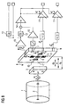
- FIG. 8 is a possible overall system.
- FIG. 1 shows an angle sensor 8 with a rotor 2 of a brushless electric motor on which a rotatable element 3 for varying a field is arranged.
- the rotatable element 3 is embodied here as a dipole magnet, wherein the north pole N and the south pole S are shown.
- a first linearly independent vector 15 of the field strength denoted here by H X and a second linearly independent vector 16 of the field strength, denoted here by H Y , are induced in the sensor chip 9 of the angle sensor 8 .
- These vectors 15 , 16 are generated by a magnetic field and are strictly dependent on the rotational angle ⁇ and the associated position of the rotatable element 3 .
- the first sensor element 4 embodied as a vertical Hall element
- the second sensor element 5 embodied as a vertical Hall element in the sensor chip 9 , senses the components of the first linearly independent magnetic field vector 15 and of the second linearly independent magnetic field vector 16 .
- the absolute value of the linearly independent magnetic field vectors 15 and 16 is particularly highly dependent on the distance d between the plane in which the first sensor element 4 and the second sensor element 5 are arranged and the plane in which the rotatable element 3 rotates in order to vary the magnetic field.
- the distance d between the rotatable element 3 and the sensor chip 9 on which the first sensor element 4 and the second sensor element 5 are arranged becomes smaller, relatively high Hall voltages are generated in the sensor elements 4 , 5 , and if the distance d between the rotatable element 3 and the sensor chip 9 becomes larger, significantly lower Hall voltages are generated in the first sensor element 4 and the second sensor element 5 .
- the uncontrolled output signals of the first sensor element 4 and of the second sensor element 5 become partially unusable for the further signal processing since they are either too small in order to utilize the full resolution of an analog/digital converter, or are so large that, for example, an analog/digital converter is overdriven, wherein part of the signal is cut off.
- FIG. 2 shows the sine-shaped and cosine-shaped output signals of the first sensor element 4 and of the second sensor element 5 with a constant distance d between the rotatable element 3 and the sensor chip 9 that forms the plane in which the first sensor element 4 and the second sensor element 5 are arranged.
- clean sine profiles and cosine profiles can be seen for the Hall voltage U Hall , which permit unambiguous resolution of the rotational angle ⁇ of between ⁇ 180° and +180°, and as a result of which the full circle can be completely and clearly sensed by the angle sensor 8 specified here.
- FIG. 2 a shows the output signal of the first sensor element 4 or of the second sensor element 5 for different distances d, d 1 , d 2 between the rotatable element 3 and the plane of the first sensor element 4 and of the second sensor element 5 .
- the optimum distance is denoted here by d
- a distance smaller than the optimum one is denoted by d 1
- a distance larger than the optimum one between the rotatable element 3 and the plane of the first sensor element and of the second sensor element 5 is denoted by d 2 .
- d 1 a distance smaller than the optimum one between the rotatable element 3 and the plane of the first sensor element and of the second sensor element 5
- d 2 For the sake of simplicity, only the sine profile of the signal of the first sensor element 4 is illustrated in FIG. 2 a , wherein the cosine profile of the signal of the second sensor element 5 would behave in an analogous fashion.
- the sine signal which can be seen here is cut off at cutoff voltage U g since the subsequent analog/digital converter is overdriven, as a result of which no resolution at all of the rotational angle of the rotor 2 can be achieved any more in wide rotational angle ranges.
- Both the increased distance d 2 and the reduced distance d 1 between the rotatable element 3 and the plane of the first sensor element 4 and of the second sensor element 5 lead to very poor measurement results which are not acceptable within the scope of application of the angle sensor 8 in automobile technology.
- FIG. 3 shows an angle sensor 8 based on the principle of electromagnetic induction of a field in the first sensor element 4 and the second sensor element 5 .
- the sensor elements 4 , 5 are embodied as coil arrangements, for example on a printed circuit board 9 .
- the rotatable element 3 is designed here to vary an electromagnetic field and is connected to the rotor 2 of the brushless electromotor 1 .
- the electromagnetic field is sensed by the first sensor element 4 and the second sensor element 5 , embodied here as a pair of coils on a sensor printed circuit board 9 .
- In an integrated circuit 21 on the sensor printed circuit board 9 there are the analysis electronics for the signals of the first sensor element 4 and the second sensor element 5 .
- These analysis electronics are composed of amplifiers 10 , controlled amplifiers 11 , which are also referred to as operational amplifiers, low-pass filters 12 , high-pass filters 13 and inverters 14 .
- FIG. 4 shows the design of a 2-D Hall element known in principle from FIG. 1 expanded by a third dimension to form the 3-D Hall element.
- the first sensor element 4 and the second sensor element 5 which form, with the sensor chip 9 , the plane in which the magnetic field induced by the element 3 in order to vary the magnetic field, is measured.
- the element 3 for varying the magnetic field is embodied here as a permanent magnet with a north pole N and south pole S.
- there is a third sensor element 6 as a result of which the sensor chip 9 shown here is expanded to what is referred to as a 3-dimensional Hall element (3-D Hall element).
- a temperature sensor element 7 is integrated into the sensor chip 9 .
- This temperature sensor element 7 measures the temperature prevailing in the angle sensor 8 . Changes in temperature in the angle sensor 8 , in particular in the sensor elements 4 , 5 and 6 , can lead to a massive change in the signals generated by the sensor elements 4 , 5 and 6 .
- the sensor elements 4 and 5 sense at least a first and a second vector 15 and 16 , independent of one another, of the field H X , H Y in this plane.
- a third vector 17 which is linearly independent of the first and second vectors 15 and 16 and which represents the absolute value of the field H Z in the z direction, is sensed, wherein this absolute value is dependent on the distance d between the plane and the rotatable element 3 , and wherein the amplitude of the signals of the sensor elements 4 and 5 is controlled with this absolute value.
- the first sensor element 4 and second sensor element 5 are arranged here in the plane of the sensor chip 9 .
- the magnetic field vectors 15 and 16 which are sensed by the first sensor element 4 and the second sensor element 5 are as electric signals to the controllable amplifiers 11 .
- These controllable amplifiers 11 are generally embodied as operational amplifiers. Since the signals which are sensed by the first sensor element 4 and the second sensor element 5 are greatly dependent on the distance d between the rotatable element 3 and the plane of the sensor chip 9 , the distance d is sensed by the third sensor element 6 , which measures the z component of the magnetic field H Z here.
- the signal which is sensed by the third sensor element 6 is fed via a first amplifier 10 and a low-pass filter 12 , which filters away high-frequency signals to an analog inverter 14 , as a result of which control variables for the controllable amplifiers 11 are available here with which the signal strength of the distance d, d 1 , d 2 between the rotatable element 3 and the plane of the sensor chip is tracked in a manner corresponding to the first sensor element 4 and the second sensor element 5 .
- These corrected signals from the first sensor element 4 and the second sensor element 5 are then made available to analog/digital converters, which can therefore always operate in the full range of their resolution and bandwidth without being overdriven in this instance.
- the temperature T of the temperature sensor element 7 is sensed, which temperature prevails within the angle sensor 8 .
- This temperature measurement value can also be included by means of an amplifier 10 in the correction of the signals from the first sensor element 4 and from the second sensor element 5 .
- FIG. 5 shows a high-pass filter 13 . The available signals are illustrated.
- the signal from the third sensor element 6 it is possible, after amplification 10 and high-pass filtering 13 , to detect a rapid change in distance between the rotatable element 3 and the sensor chip 9 .
- This rapid change in distance would provide, for example, an indication of a defective bearing of the rotor 2 in the brushless electric motor 1 .
- the low-pass filtering 12 of the signal from the third sensor element 6 generates a signal for a slow change in distance d between the rotatable element 3 and the plane of the sensor chip 9 . This slow change in distance can be triggered by temperature expansion of the overall system.
- FIG. 6 shows a further refinement of the invention.
- the further variable 17 dependent on the distance d, d 1 , d 2 , is derived from the first and second vectors 15 , 16 which are linearly independent of one another and which are sensed by the sensor elements 4 , 5 .
- the resulting absolute value of the first and second linearly independent vectors 15 , 16 are formed by Pythagoras's theorem in a computational circuit 19 .
- the absolute values of the individual linearly independent vectors 15 , 16 which are represented chronologically as sine signals and cosine signals, are larger when there is a relatively small distance d 1 between the rotatable element 3 and the plane of the first sensor element 4 and of the second sensor element 5 , and become smaller as the distance increases.
- the computation circuit 19 can supply largely angle-independent information about the distance d between the rotatable element 3 and the plane of the first sensor element 4 and of the second sensor element 5 .
- FIG. 7 shows a subsequent refinement of the invention.
- the further variable 17 which is dependent on the distance the distance d between the rotatable element 3 and the plane of the first sensor element 4 and of the second sensor element 5 is derived here from the supply current 20 for operating the inductive sensor elements 4 , 5 .
- an electromagnetic alternating field is generated, as a result of which an eddy current is induced in the rotatable element 3 .
- the absolute value of the eddy current rises as the distance d becomes smaller and falls as the distance d becomes larger.
- the absolute values of the linearly independent vectors 15 , 16 in their chronological representation as sine signals and cosine signals also become larger as the distance d 1 becomes smaller and fall as the distance d 2 becomes larger.
- the computational circuit 19 can therefore also provide largely angle-independent information about the distance d between the rotatable element 3 and the plane of the first sensor element 4 and of the second sensor element 5 .
- FIG. 8 The representation of a possible overall system is found in FIG. 8 .
- a brushless electromotor 1 is illustrated with a rotor 2 , wherein the rotatable element 3 for varying a magnetic field is arranged on the rotor 2 .
- the rotatable element 3 will induce a characteristic magnetic field in the sensor chip 9 .
- This characteristic magnetic field is picked up by the first sensor element 4 , the second sensor element 5 and the third sensor element 6 .
- the distance between the rotatable element 3 and the sensor chip 9 can vary, which is represented by the reference symbols d 2 , d 1 and d 0 here.
- This variation in the distance d between the rotatable element 3 and the plane in which the first sensor element 4 and the second sensor element 5 are arranged is sensed by the third sensor element 6 by the magnetic field component H Z .
- the third sensor element 6 provides a correction value H Z that is fed to the controllable amplifiers 11 via the first amplifier 10 and a low-pass filter 12 as well as an inverter 14 .
- the magnetic field values H Y and H Z are sensed by the first sensor element 4 and the second sensor element 5 , as a result of which the first sensor element 4 acquires a first linearly independent vector 15 and the second sensor element 5 senses a second linearly independent vector 16 .
- the angle ⁇ can be inferred clearly by a CORDIC algorithm on the basis of the combination of these two linearly independent vectors.
- the distance dependence between the rotatable element 3 and the sensor chip 9 is corrected in the controllable amplifiers 11 , as a result of which a clear resolution, which is high in terms of measuring technology, of the 360° full circle is possible with the angle sensor 8 illustrated here.
Landscapes
- Physics & Mathematics (AREA)
- General Physics & Mathematics (AREA)
- Engineering & Computer Science (AREA)
- Signal Processing (AREA)
- Transmission And Conversion Of Sensor Element Output (AREA)
- Measurement Of Length, Angles, Or The Like Using Electric Or Magnetic Means (AREA)
Abstract
Description
Claims (13)
Applications Claiming Priority (4)
| Application Number | Priority Date | Filing Date | Title |
|---|---|---|---|
| DE102009042473.3A DE102009042473B4 (en) | 2009-09-24 | 2009-09-24 | Method for evaluating signals of an angle sensor |
| DE102009042473.3 | 2009-09-24 | ||
| DE102009042473 | 2009-09-24 | ||
| PCT/EP2010/064027 WO2011036196A1 (en) | 2009-09-24 | 2010-09-23 | Method for analyzing signals from an angle sensor |
Publications (2)
| Publication Number | Publication Date |
|---|---|
| US20120176070A1 US20120176070A1 (en) | 2012-07-12 |
| US9080896B2 true US9080896B2 (en) | 2015-07-14 |
Family
ID=43091643
Family Applications (1)
| Application Number | Title | Priority Date | Filing Date |
|---|---|---|---|
| US13/498,091 Expired - Fee Related US9080896B2 (en) | 2009-09-24 | 2010-09-23 | Method for analyzing signals from an angle sensor |
Country Status (7)
| Country | Link |
|---|---|
| US (1) | US9080896B2 (en) |
| EP (1) | EP2480861B8 (en) |
| JP (1) | JP5523571B2 (en) |
| KR (1) | KR20120088677A (en) |
| CN (1) | CN102549386B (en) |
| DE (1) | DE102009042473B4 (en) |
| WO (1) | WO2011036196A1 (en) |
Cited By (6)
| Publication number | Priority date | Publication date | Assignee | Title |
|---|---|---|---|---|
| US9933495B2 (en) | 2014-03-31 | 2018-04-03 | Tdk-Micronas Gmbh | Sensor device |
| US10491084B2 (en) * | 2016-07-11 | 2019-11-26 | Jtekt Corporation | Motor device |
| CN110658354A (en) * | 2018-06-28 | 2020-01-07 | 英飞凌科技股份有限公司 | Sensor device and method for producing a sensor device |
| US10816361B2 (en) | 2016-02-17 | 2020-10-27 | Vitesco Technologies GmbH | Arrangement for detecting the angular position of a rotatable component |
| US11199151B2 (en) * | 2019-06-26 | 2021-12-14 | Cummins Inc. | Vehicle controller with complementary capacitance for analog-to-digital converter (A/D) low pass filter |
| US12578572B2 (en) | 2019-08-31 | 2026-03-17 | Hesai Technology Co., Ltd. | Method for measuring deflection angle of galvanometer scanner, and laser radar using method |
Families Citing this family (38)
| Publication number | Priority date | Publication date | Assignee | Title |
|---|---|---|---|---|
| US8857464B2 (en) | 2008-01-30 | 2014-10-14 | Flowserve Management Company | Valve actuators having magnetic angle sensors |
| JP5895774B2 (en) * | 2012-09-04 | 2016-03-30 | 株式会社安川電機 | motor |
| JP6056482B2 (en) | 2013-01-08 | 2017-01-11 | 株式会社ジェイテクト | Abnormality detection device for rotation angle sensor |
| FR3003957B1 (en) * | 2013-03-29 | 2015-09-04 | Ntn Snr Roulements | SENSOR FOR DETECTING A PERIODIC MAGNETIC FIELD |
| CN203260444U (en) | 2013-04-01 | 2013-10-30 | 江苏多维科技有限公司 | Non-contact potentiometer |
| DE102014005247B4 (en) * | 2014-04-10 | 2020-12-10 | Tdk-Micronas Gmbh | Sensor device |
| CN203809329U (en) * | 2014-04-14 | 2014-09-03 | 江苏多维科技有限公司 | Direct-current fan control chip |
| DE102014219298B4 (en) * | 2014-09-24 | 2024-12-05 | Schaeffler Technologies AG & Co. KG | Method for increasing the accuracy of an output signal of a magnetic field sensor for angular position detection of a rotating component |
| CN104776867B (en) * | 2015-03-27 | 2017-09-29 | 联想(北京)有限公司 | The determination method and electronic equipment of first object and the second object relative position relation |
| DE102015210586A1 (en) * | 2015-06-10 | 2016-12-15 | Schaeffler Technologies AG & Co. KG | Method for operating a revolution sensor and corresponding revolution sensor |
| JP6619974B2 (en) * | 2015-08-28 | 2019-12-11 | 日本電産サンキョー株式会社 | Encoder |
| DE102015218855A1 (en) * | 2015-09-30 | 2017-03-30 | Siemens Aktiengesellschaft | Signal transmitter with improved detection of the angle signal |
| DE102015218945A1 (en) * | 2015-09-30 | 2017-03-30 | Infineon Technologies Ag | Signal transmitter with improved detection of the angle signal |
| US10048328B2 (en) * | 2015-11-05 | 2018-08-14 | Infineon Technologies Ag | Redundant magnetic angle sensor with improved accuracy |
| KR102542137B1 (en) * | 2015-11-09 | 2023-06-12 | 엘지이노텍 주식회사 | Detecting device for sensing the rotor position and method thereof |
| US9879775B2 (en) * | 2015-11-13 | 2018-01-30 | Sl Corporation | Shifting lever assembly |
| CN105656282B (en) * | 2016-02-01 | 2017-12-01 | 重庆理工大学 | A kind of linear permanent-magnet servomotor with embedded position detecting device |
| CN105490596B (en) * | 2016-02-01 | 2017-12-08 | 重庆理工大学 | A kind of embedded position detecting system of permanent-magnet alternating current servo motor |
| JP6354961B2 (en) * | 2016-05-20 | 2018-07-11 | Tdk株式会社 | State determination device and method, physical quantity information generation device, and angle sensor |
| CN106197254A (en) * | 2016-06-23 | 2016-12-07 | 上海电机学院 | Hall-type angular transducer based on radial magnetizing |
| DE102017114511A1 (en) * | 2017-06-29 | 2019-01-03 | Schaeffler Technologies AG & Co. KG | Method for adjusting a position of a magnet to a GMR sensor |
| DE102017211991B3 (en) | 2017-07-13 | 2018-07-05 | Continental Automotive Gmbh | Arrangement for detecting the angular position of a rotatable component |
| DE102017211996B4 (en) | 2017-07-13 | 2025-07-31 | Schaeffler Technologies AG & Co. KG | Sensor unit and arrangement for detecting the position of a component |
| DE102017211994B4 (en) | 2017-07-13 | 2019-05-16 | Continental Automotive Gmbh | Sensor unit and arrangement for detecting the position of a component |
| DE102017128869B3 (en) * | 2017-12-05 | 2019-05-29 | Infineon Technologies Ag | Magnetic angle sensor arrangement and method for estimating a rotation angle |
| KR102688774B1 (en) | 2018-02-16 | 2024-07-26 | 아날로그 디바이시즈 글로벌 언리미티드 컴퍼니 | Position sensor and position sensing method |
| DE102018213017A1 (en) | 2018-08-03 | 2020-02-06 | Continental Automotive Gmbh | Method and device for determining the relative position of two coils to one another |
| US10914611B2 (en) | 2018-08-27 | 2021-02-09 | Nxp B.V. | Magnetic field sensor system and method for rotation angle measurement |
| US11162815B2 (en) * | 2018-09-14 | 2021-11-02 | Allegro Microsystems, Llc | Angular magnetic field sensor and rotating target with stray field immunity |
| CN110208724A (en) * | 2019-04-28 | 2019-09-06 | 北京锐达芯集成电路设计有限责任公司 | A kind of chip |
| WO2021000294A1 (en) * | 2019-07-03 | 2021-01-07 | Hamlin Electronics (Suzhou) Ltd. | Apparatus for detection of angular movement of a ferromagnetic vane |
| KR102342745B1 (en) * | 2019-11-25 | 2021-12-28 | 황재용 | Development of high precision wheel speed sensor |
| EP4148395B1 (en) | 2021-09-09 | 2025-01-01 | Melexis Technologies SA | Magnetic sensor devices, systems and methods, and a force sensor |
| EP4399489A1 (en) * | 2021-09-09 | 2024-07-17 | Melexis Technologies SA | Magnetic sensor devices, systems and methods, and a force sensor |
| EP4403880A1 (en) * | 2023-01-18 | 2024-07-24 | Schneider Electric Industries SAS | Communication in multi-carrier systems, linear motors, transport devices |
| CN117704956B (en) * | 2024-02-05 | 2024-04-26 | 国机传感科技有限公司 | Flat angle sensor and measuring method |
| DE102024208614A1 (en) * | 2024-09-10 | 2024-11-14 | Brose Fahrzeugteile SE & Co. Kommanditgesellschaft, Coburg | Method and device for operating an electrical adjustment mechanism |
| CN119382431B (en) * | 2024-10-25 | 2026-01-06 | 广东汇天航空航天科技有限公司 | An electric motor and its position sensor |
Citations (16)
| Publication number | Priority date | Publication date | Assignee | Title |
|---|---|---|---|---|
| JPH02307012A (en) | 1989-05-23 | 1990-12-20 | Shinano Denki Kk | Magnetic encoder |
| DE4319322A1 (en) | 1993-06-11 | 1994-12-15 | Heidenhain Gmbh Dr Johannes | Position measuring device |
| US5463393A (en) * | 1991-12-05 | 1995-10-31 | Acutronic Ag | Method and apparatus for correcting errors in an amplitude encoded signal |
| US5606254A (en) * | 1995-10-19 | 1997-02-25 | General Motors Corporation | Rotation sensor employing coil wound on assembly of a core interposed between two magnets |
| US6229299B1 (en) * | 1998-11-17 | 2001-05-08 | Caterpillar Inc. | System and method for computing the angular velocity and direction of a rotational body |
| DE10143286A1 (en) | 2000-09-14 | 2002-04-04 | Delphi Tech Inc | Rotation sensor has orthogonal Hall effect sensors creates temperature compensation signal |
| CN1343889A (en) | 2000-08-21 | 2002-04-10 | 桑特隆股份公司 | Sensor for detecting magnetic field direction |
| US20050030012A1 (en) | 2003-07-29 | 2005-02-10 | Tech3 E. K. | Angle of rotation sensor |
| US6956366B2 (en) * | 2002-03-07 | 2005-10-18 | Koninklijke Philips Electronics N.V. | Arrangement for determining the position of a motion sensor element influencing the formation of a magnetic field of a working magnet along its motion coordinate |
| CN1789920A (en) | 2004-12-16 | 2006-06-21 | 阿尔卑斯电气株式会社 | Method of calculating compensation value for angle detecting sensor and angle detecting sensor using the method |
| EP1697697A1 (en) | 2003-11-18 | 2006-09-06 | Koninklijke Philips Electronics N.V. | Position determining |
| CN100406895C (en) | 2003-01-17 | 2008-07-30 | 东海旅客铁道株式会社 | Wheel speed detection system |
| US20090001964A1 (en) * | 2007-06-29 | 2009-01-01 | Bernhard Strzalkowski | Integrated Hybrid Current Sensor |
| US20090102460A1 (en) * | 2007-07-27 | 2009-04-23 | Melexis Nv Microelectronic Integrated Systems | Position sensor |
| WO2009099054A1 (en) * | 2008-02-07 | 2009-08-13 | Hitachi Metals, Ltd. | Rotation angle detection device, rotary machine, and rotation angle detection method |
| EP2101157A2 (en) | 2008-03-14 | 2009-09-16 | Polycontact AG | Magnetic rotating angle sensor |
-
2009
- 2009-09-24 DE DE102009042473.3A patent/DE102009042473B4/en not_active Expired - Fee Related
-
2010
- 2010-09-23 WO PCT/EP2010/064027 patent/WO2011036196A1/en not_active Ceased
- 2010-09-23 CN CN201080042680.3A patent/CN102549386B/en active Active
- 2010-09-23 US US13/498,091 patent/US9080896B2/en not_active Expired - Fee Related
- 2010-09-23 KR KR1020127007433A patent/KR20120088677A/en not_active Withdrawn
- 2010-09-23 EP EP10765595.3A patent/EP2480861B8/en active Active
- 2010-09-23 JP JP2012530255A patent/JP5523571B2/en not_active Expired - Fee Related
Patent Citations (23)
| Publication number | Priority date | Publication date | Assignee | Title |
|---|---|---|---|---|
| JPH02307012A (en) | 1989-05-23 | 1990-12-20 | Shinano Denki Kk | Magnetic encoder |
| US5463393A (en) * | 1991-12-05 | 1995-10-31 | Acutronic Ag | Method and apparatus for correcting errors in an amplitude encoded signal |
| DE4319322A1 (en) | 1993-06-11 | 1994-12-15 | Heidenhain Gmbh Dr Johannes | Position measuring device |
| JPH0755408A (en) | 1993-06-11 | 1995-03-03 | Dr Johannes Heidenhain Gmbh | Position measuring device |
| US5627466A (en) * | 1993-06-11 | 1997-05-06 | Dr. Johannes Heidenhain Gmbh | Position measuring device having a sensor for sensing the distance between a scanning unit and a scale |
| US5606254A (en) * | 1995-10-19 | 1997-02-25 | General Motors Corporation | Rotation sensor employing coil wound on assembly of a core interposed between two magnets |
| US6229299B1 (en) * | 1998-11-17 | 2001-05-08 | Caterpillar Inc. | System and method for computing the angular velocity and direction of a rotational body |
| CN1343889A (en) | 2000-08-21 | 2002-04-10 | 桑特隆股份公司 | Sensor for detecting magnetic field direction |
| DE10143286A1 (en) | 2000-09-14 | 2002-04-04 | Delphi Tech Inc | Rotation sensor has orthogonal Hall effect sensors creates temperature compensation signal |
| US6566860B1 (en) * | 2000-09-14 | 2003-05-20 | Delphi Technologies, Inc. | Method for temperature compensation for the output of an angular position sensor |
| US6956366B2 (en) * | 2002-03-07 | 2005-10-18 | Koninklijke Philips Electronics N.V. | Arrangement for determining the position of a motion sensor element influencing the formation of a magnetic field of a working magnet along its motion coordinate |
| CN100406895C (en) | 2003-01-17 | 2008-07-30 | 东海旅客铁道株式会社 | Wheel speed detection system |
| US20050030012A1 (en) | 2003-07-29 | 2005-02-10 | Tech3 E. K. | Angle of rotation sensor |
| EP1697697A1 (en) | 2003-11-18 | 2006-09-06 | Koninklijke Philips Electronics N.V. | Position determining |
| US20070093980A1 (en) | 2003-11-18 | 2007-04-26 | Koninklijke Philips Electronics N.V. | Position determining |
| JP2007511778A (en) | 2003-11-18 | 2007-05-10 | コーニンクレッカ フィリップス エレクトロニクス エヌ ヴィ | Positioning apparatus and method |
| US7401001B2 (en) * | 2003-11-18 | 2008-07-15 | Koninklijke Philips Electronics N.V. | Position determining |
| EP1697697B1 (en) | 2003-11-18 | 2008-11-05 | Koninklijke Philips Electronics N.V. | Position determining |
| CN1789920A (en) | 2004-12-16 | 2006-06-21 | 阿尔卑斯电气株式会社 | Method of calculating compensation value for angle detecting sensor and angle detecting sensor using the method |
| US20090001964A1 (en) * | 2007-06-29 | 2009-01-01 | Bernhard Strzalkowski | Integrated Hybrid Current Sensor |
| US20090102460A1 (en) * | 2007-07-27 | 2009-04-23 | Melexis Nv Microelectronic Integrated Systems | Position sensor |
| WO2009099054A1 (en) * | 2008-02-07 | 2009-08-13 | Hitachi Metals, Ltd. | Rotation angle detection device, rotary machine, and rotation angle detection method |
| EP2101157A2 (en) | 2008-03-14 | 2009-09-16 | Polycontact AG | Magnetic rotating angle sensor |
Non-Patent Citations (1)
| Title |
|---|
| English translation of an Office Action dated Sep. 2, 2014 issued in the corresponding Chinese Patent Application No. 2010800426803. |
Cited By (10)
| Publication number | Priority date | Publication date | Assignee | Title |
|---|---|---|---|---|
| US9933495B2 (en) | 2014-03-31 | 2018-04-03 | Tdk-Micronas Gmbh | Sensor device |
| US10816361B2 (en) | 2016-02-17 | 2020-10-27 | Vitesco Technologies GmbH | Arrangement for detecting the angular position of a rotatable component |
| US10491084B2 (en) * | 2016-07-11 | 2019-11-26 | Jtekt Corporation | Motor device |
| CN110658354A (en) * | 2018-06-28 | 2020-01-07 | 英飞凌科技股份有限公司 | Sensor device and method for producing a sensor device |
| US11150260B2 (en) * | 2018-06-28 | 2021-10-19 | Infineon Technologies Ag | Sensor devices and methods for producing sensor devices |
| CN110658354B (en) * | 2018-06-28 | 2022-02-15 | 英飞凌科技股份有限公司 | Sensor device and method of making sensor device |
| US11199151B2 (en) * | 2019-06-26 | 2021-12-14 | Cummins Inc. | Vehicle controller with complementary capacitance for analog-to-digital converter (A/D) low pass filter |
| US20220099044A1 (en) * | 2019-06-26 | 2022-03-31 | Cummins Inc. | Vehicle controller with complementary capacitance for analog-to-digital converter (a/d) low pass filter |
| US11686267B2 (en) * | 2019-06-26 | 2023-06-27 | Cummins Inc. | Vehicle controller with complementary capacitance for analog-to-digital converter (A/D) low pass filter |
| US12578572B2 (en) | 2019-08-31 | 2026-03-17 | Hesai Technology Co., Ltd. | Method for measuring deflection angle of galvanometer scanner, and laser radar using method |
Also Published As
| Publication number | Publication date |
|---|---|
| CN102549386B (en) | 2016-02-17 |
| US20120176070A1 (en) | 2012-07-12 |
| WO2011036196A1 (en) | 2011-03-31 |
| JP5523571B2 (en) | 2014-06-18 |
| EP2480861B8 (en) | 2019-12-18 |
| CN102549386A (en) | 2012-07-04 |
| EP2480861A1 (en) | 2012-08-01 |
| DE102009042473B4 (en) | 2019-01-24 |
| EP2480861B1 (en) | 2019-07-17 |
| JP2013506118A (en) | 2013-02-21 |
| DE102009042473A1 (en) | 2011-04-07 |
| KR20120088677A (en) | 2012-08-08 |
Similar Documents
| Publication | Publication Date | Title |
|---|---|---|
| US9080896B2 (en) | Method for analyzing signals from an angle sensor | |
| EP3640602B1 (en) | Method for detecting errors in a rotating position sensor system having sine and cosine signals | |
| JP5745160B2 (en) | Differential magnetic field sensor structure for orientation independent measurement | |
| JP5613839B2 (en) | Method and apparatus for absolute positioning of a moving object | |
| US8106649B2 (en) | Angle detecting apparatus and angle detecting method | |
| JP6359079B2 (en) | Hall sensor insensitive to external magnetic field | |
| KR102195533B1 (en) | Rotary encoder and angle correction method of rotary encoder | |
| US10508897B2 (en) | Magnet device and position sensing system | |
| CN113412574B (en) | Method for determining the angle of a rotor of an electric motor, controller and vehicle | |
| CN110546463A (en) | Method for determining the angular position of a rotating component, in particular of an electric motor of a clutch actuation system for a vehicle | |
| CN114649985B (en) | Methods for determining jumping | |
| US20110054832A1 (en) | Method and device for the robust and efficient determination of the rotational direction and/or rotational speed of a wheel or a shaft | |
| JP5176208B2 (en) | Rotation angle detection method and rotation angle sensor | |
| WO2007055135A1 (en) | Magnetic encoder device | |
| US20120133357A1 (en) | Hybrid sensor arrangement | |
| US20080218159A1 (en) | Sensor System For Determining a Position or a Rotational Speed of an Object | |
| CN102713525A (en) | Method, device and system for monitoring the determination of a rotor angle of a rotating shaft by means of a resolver | |
| JP4725109B2 (en) | Brushless motor | |
| Santos et al. | Foucault's currents based position sensor | |
| JP2003207365A (en) | Rotation angle sensor |
Legal Events
| Date | Code | Title | Description |
|---|---|---|---|
| AS | Assignment |
Owner name: CONTINENTAL AUTOMOTIVE GMBH, GERMANY Free format text: ASSIGNMENT OF ASSIGNORS INTEREST;ASSIGNOR:WALLRAFEN, WERNER;REEL/FRAME:027920/0884 Effective date: 20120312 |
|
| STCF | Information on status: patent grant |
Free format text: PATENTED CASE |
|
| FEPP | Fee payment procedure |
Free format text: PAYOR NUMBER ASSIGNED (ORIGINAL EVENT CODE: ASPN); ENTITY STATUS OF PATENT OWNER: LARGE ENTITY |
|
| MAFP | Maintenance fee payment |
Free format text: PAYMENT OF MAINTENANCE FEE, 4TH YEAR, LARGE ENTITY (ORIGINAL EVENT CODE: M1551); ENTITY STATUS OF PATENT OWNER: LARGE ENTITY Year of fee payment: 4 |
|
| AS | Assignment |
Owner name: VITESCO TECHNOLOGIES GMBH, GERMANY Free format text: ASSIGNMENT OF ASSIGNORS INTEREST;ASSIGNOR:CONTINENTAL AUTOMOTIVE GMBH;REEL/FRAME:053371/0846 Effective date: 20200601 |
|
| FEPP | Fee payment procedure |
Free format text: MAINTENANCE FEE REMINDER MAILED (ORIGINAL EVENT CODE: REM.); ENTITY STATUS OF PATENT OWNER: LARGE ENTITY |
|
| LAPS | Lapse for failure to pay maintenance fees |
Free format text: PATENT EXPIRED FOR FAILURE TO PAY MAINTENANCE FEES (ORIGINAL EVENT CODE: EXP.); ENTITY STATUS OF PATENT OWNER: LARGE ENTITY |
|
| STCH | Information on status: patent discontinuation |
Free format text: PATENT EXPIRED DUE TO NONPAYMENT OF MAINTENANCE FEES UNDER 37 CFR 1.362 |
|
| FP | Lapsed due to failure to pay maintenance fee |
Effective date: 20230714 |