US9068849B2 - Method and system for reducing shape points in a geographic data information system - Google Patents
Method and system for reducing shape points in a geographic data information system Download PDFInfo
- Publication number
- US9068849B2 US9068849B2 US13/318,785 US200913318785A US9068849B2 US 9068849 B2 US9068849 B2 US 9068849B2 US 200913318785 A US200913318785 A US 200913318785A US 9068849 B2 US9068849 B2 US 9068849B2
- Authority
- US
- United States
- Prior art keywords
- clothoid
- shape point
- shaped line
- remainder
- determined
- Prior art date
- Legal status (The legal status is an assumption and is not a legal conclusion. Google has not performed a legal analysis and makes no representation as to the accuracy of the status listed.)
- Active, expires
Links
Images


Classifications
-
- G—PHYSICS
- G01—MEASURING; TESTING
- G01C—MEASURING DISTANCES, LEVELS OR BEARINGS; SURVEYING; NAVIGATION; GYROSCOPIC INSTRUMENTS; PHOTOGRAMMETRY OR VIDEOGRAMMETRY
- G01C21/00—Navigation; Navigational instruments not provided for in groups G01C1/00 - G01C19/00
- G01C21/38—Electronic maps specially adapted for navigation; Updating thereof
- G01C21/3863—Structures of map data
- G01C21/3867—Geometry of map features, e.g. shape points, polygons or for simplified maps
-
- G—PHYSICS
- G01—MEASURING; TESTING
- G01C—MEASURING DISTANCES, LEVELS OR BEARINGS; SURVEYING; NAVIGATION; GYROSCOPIC INSTRUMENTS; PHOTOGRAMMETRY OR VIDEOGRAMMETRY
- G01C21/00—Navigation; Navigational instruments not provided for in groups G01C1/00 - G01C19/00
- G01C21/26—Navigation; Navigational instruments not provided for in groups G01C1/00 - G01C19/00 specially adapted for navigation in a road network
- G01C21/28—Navigation; Navigational instruments not provided for in groups G01C1/00 - G01C19/00 specially adapted for navigation in a road network with correlation of data from several navigational instruments
- G01C21/30—Map- or contour-matching
- G01C21/32—Structuring or formatting of map data
-
- G—PHYSICS
- G06—COMPUTING OR CALCULATING; COUNTING
- G06F—ELECTRIC DIGITAL DATA PROCESSING
- G06F16/00—Information retrieval; Database structures therefor; File system structures therefor
- G06F16/20—Information retrieval; Database structures therefor; File system structures therefor of structured data, e.g. relational data
- G06F16/29—Geographical information databases
-
- G06F17/30241—
-
- G—PHYSICS
- G09—EDUCATION; CRYPTOGRAPHY; DISPLAY; ADVERTISING; SEALS
- G09B—EDUCATIONAL OR DEMONSTRATION APPLIANCES; APPLIANCES FOR TEACHING, OR COMMUNICATING WITH, THE BLIND, DEAF OR MUTE; MODELS; PLANETARIA; GLOBES; MAPS; DIAGRAMS
- G09B29/00—Maps; Plans; Charts; Diagrams, e.g. route diagram
- G09B29/10—Map spot or coordinate position indicators; Map reading aids
- G09B29/102—Map spot or coordinate position indicators; Map reading aids using electrical means
Definitions
- the present invention relates to methods and systems for use digital map databases and systems using such databases, for example Geographic Information Systems (GIS), navigation systems or devices (portable navigation devices, navigation enabled computing devices e.g. PDAs, phones and the like), route calculation software and apparatus using such software.
- GIS Geographic Information Systems
- navigation systems or devices portable navigation devices, navigation enabled computing devices e.g. PDAs, phones and the like
- route calculation software and apparatus using such software.
- embodiments of the invention relate to methods and system associated with shape information representing linear features in map databases.
- Map data stored in digital map databases frequently represents linear features, such as roads, train lines, boundaries (recreational, political, land), supply lines etc., as shaped lines.
- a shaped line 100 is defined by two or more shape points 110 , 120 , 130 , 140 , 150 connected by straight lines or chords, as shown in FIG. 1 .
- the shape points 110 , 120 , 130 , 140 , 150 may have been derived from measurements made of the feature using, for example, GPS-based equipment.
- various problems have been identified with representations of linear features, particularly in map databases.
- FIG. 1 illustrates an example shaped line derived from location measurements
- FIG. 2 illustrates a method according to an embodiment of the invention
- FIG. 3 illustrates a clothoid spline corresponding to the shaped line of FIG. 1 ;
- FIG. 4 illustrates curvature values for clothoid sections of the clothoid spline
- FIGS. 5 to 9 illustrate sample code according to embodiments of the invention
- FIG. 10 illustrates a resultant shaped line produced by an embodiment of the invention
- FIG. 11 is a close-up view of a portion of the resultant shaped line
- FIG. 12 is a method according to a further embodiment of the invention.
- FIGS. 13 and 14 are sample code according to embodiments of the invention.
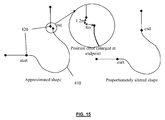
- FIG. 15 is an illustration of proportional shaped line adjustment according to an embodiment of the invention.
- FIG. 1 is an illustration of a shaped line 100 following a path.
- the shaped line 100 shown in FIG. 1 is based upon location measurements determined, for example, by a GPS-based location measuring device. It will be realised however that embodiments of the invention may be applied to shaped lines from any source.
- a shaped line may be produced by an operator, using a map editing tools, who places path points in order to generate roadway shapes according to aerial imagery or external maps.
- a shaped line may alternately be produced by a theoretical simulation of a process, such as a conflation process.
- the resultant shaped line be representative of the reference shaped line 100 to within 1 m and remain within ⁇ 2 m of the reference shaped line 100 .
- the shaped line 100 corresponds to measurement of a traffic ramp which exits an eastbound motorway, first curving rightward (southeasterly) as it diverges from traffic, for 200 meters, then (from 200 m to 600 m) gradually reversing the direction of curvature until it reaches a region of constant left-hand curvature from 600 m to 1000 m. From 1000 m to 1400 m the curvature changes gradually from left-hand to right hand, and from 1400 to 1600 the curvature remains constant until the ramp merges with northbound traffic. As captured, the measured data contains both jitter (error of individual readings), and the shape point capture rate of regular 25-meter intervals is more frequent than needed for example for a navigation device. Therefore, it is desired for a shaped line created by an embodiment of the invention to have fewer shape points, thus reducing a size of data representing the ramp.
- FIG. 2 illustrates a method 200 according to an embodiment of the invention.
- the method 200 generates a shaped line based upon the reference shaped line 100 , wherein the generated shaped line includes a different number of shape points than the reference shaped line 100 .
- a clothoid spline is created which fits the path of the reference shaped line 100 within an accuracy threshold.
- a clothoid spline is determined which represents the shaped line 100 to within a predetermined accuracy threshold.
- the clothoid spline is a piecewise, continuous first order function of curvature versus travel distance along the path of the shaped line 100 .
- Any clothoid representation of the shaped line 100 is not an exact equivalent to the shaped line 100 , but rather an approximate characterization of the line.
- the choice of accuracy threshold used to generate the clothoid will dictate the level of fidelity to the original curve i.e. the ramp in the example of FIG. 1 . When the accuracy threshold is chosen wisely, a clothoid may be produced which is truer to reality than the original shaped line 100 .
- a method of generating the clothoid spline is explained in WO 2009/071995 by the present inventor, which is herein incorporated by reference.
- FIG. 3 A clothoid spline 300 determined in step 205 by the method disclosed in WO 2009/071995 is shown in FIG. 3 .
- FIG. 4 illustrates calculated curvature values for the clothoid spline determined in step 205 .
- the clothoid spline has a constant curvature of ⁇ 0.003 radians, between 200 m and 6 m the curvature various between ⁇ 0.003 and 0.005 radians, whereupon between 600 m and 1000 m the curvature is constant at 0.005 radians.
- the curvature decreases from 0.005 to ⁇ 0.003 radians and is constant at ⁇ 0.003 radians between 1400 m and 1600 m.
- embodiments of the present invention successively process each clothoid section of the clothoid spline generated in step 205 .
- Shape points are determined which fit to each clothoid section within a given fidelity level.
- a remaining error level is carried over between adjacent clothoid sections, as will be explained.
- step 210 a start location and initial heading of a first section of the clothoid spline 300 are determined.
- FIGS. 5 to 9 illustrate example code fragments which implement the method 200 .
- the code shown in FIG. 5 refers to a class ParametricClothoid which holds curvature data for the clothoid spline, for example held in an association table.
- the class also has access to the original shaped line 100 data, which is represented as a class Chain which derives from the standard class Vector.
- the chain class can return edges (the line segments between successive shape points), which themselves are instances of a Line class.
- the example code generates a new Chain, result, by traversing the clothoid spline 300 .
- Step 210 is implemented by lines 3 and 4 of the sample code in FIG. 5 .
- the generated chain, called result, is established at line 5 .
- the location and heading will be used to determine shape points corresponding to the clothoid spline 300 , as will be explained.
- a remaining error value is initially set to equal the fidelity value to which it is desired to fit the shape points to the clothoid spline 300 .
- the fidelity value may be chosen appropriate for a desired application of the shaped line e.g. based on an accuracy of a device for which the shaped line is intended.
- the error_remainder variable is set-up at line 6 of FIG. 5 .
- the error remainder value may be carried over to from a preceding clothoid section to a following clothoid section and used in the determination of first shape point for the following section.
- the error remainder value is decremented as each section of the clothoid spline is processed whenever a shape point is determined to reside at any location other than an end of the spline section.
- this allows the generation of a shaped line having a minimum number of shape points.
- embodiments of the invention may be considered which place a shape point at an end of each spline section and reset the error remainder to the fidelity value.
- step 220 an initial or start location of the clothoid spline is determined to be a first shape point for the shaped line.
- the coordinates of the first shape point are stored as a first shape point in the result chain.
- step 225 it is determined whether the current clothoid section under consideration is straight. This is accomplished in the sample code shown in FIG. 6 at lines 4 - 8 by considering whether a curvature of the clothoid section is 0 at both ends. If the clothoid section is straight then determination of a representation of such a clothoid section is simplified since it may easily represented by shape points.
- step 230 if the clothoid section is straight then the current location is incremented by a length of the clothoid section in the direction of the initial heading determined in step 210 , as at line 6 of FIG. 6 . It will be noted from the sample code in FIG. 6 that the error remainder is not decremented in step 230 since the entire error remainder is available for use in a following clothoid section, should there be one.
- a maximum increment distance from the current location is determined according to the current error remainder value.
- the determination of the maximum increment distance will be explained later, with reference to FIGS. 12 to 14 .
- a SlopeIntercept object called curve is established at lines 9 and 10 of FIG. 6 .
- the SlopeIntercept object is a representation of a linear function in x,y coordinates.
- the SlopeIntercept object returns the function's y value for any given x value.
- the SlopeIntercept class is initially constructed from two points deemed as x, y values of a linear function—the constructor calculates slope and intercept of such a function.
- the function it represents is the linear function of curvature (y) per distance traveled (x).
- the SlopeIntercept object curve can be queried for the curvature at any given travel distance along the clothoid section.
- a variable called position is established at line 11 to store a current position along the current clothoid section and is initially set to 0 i.e. the start of the clothoid section.
- step 240 the location of the incremented position i.e. the current location plus the maximum increment distance determined in step 235 is then added to the result chain as a location of a shape point.
- Sample code for adding a shape point is shown in FIG. 7 .
- a heading change between the current location and the incremented location is determined at lines 9 & 10 .
- the change in heading is determined as an average curvature multiplied by the distance over which the curvature applies.
- line 13 calculates a unit_normal, the left-hand normal vector to the heading.
- a different curvature value is calculated (line 22 ) for purposes of positioning the point. As indicated in the comment at lines 15 - 21 of FIG.
- Line 23 calculates an average unit change in position over the interval, and line 26 adds this vector, times the length, to the position (loc). The location is added to the result chain at line 27 . Finally, the heading is updated at line 29 .
- step 245 it is determined whether the location added to the result chain is within the current clothoid section. If the location is still within the current clothoid section, then the remainder value is reset to the fidelity value and the method returns to step 235 to continue adding shape points to the chain representing the current clothoid section.
- the variable position is incremented by the previously determined increment distance to move it along the clothoid section and this is compared against the length of the clothoid section at line 22 . If the position is less than the length of the clothoid section, the remainder is reset to the fidelity value in step 250 . Steps 235 - 240 are then repeated as necessary to reach the end of the current clothoid section.
- step 255 once it has been determined that the position has reached the end of the clothoid section, a remainder to be carried over to a following clothoid section is determined. Step 255 is implemented in the sample code by lines 27 to 38 shown in FIG. 6 . Firstly, an error value is determined which represents the error in placing the last shape point. In the sample code this is determined using the function errorMetric( ), sample code for which is shown in FIG. 8 , in combination with the function computeEffectiveCurvature( ), sample code for which is shown in FIG. 9 .
- the errorMetric function determines whether the clothoid section is straight and, if so, returns an error of 0 indicating that the shape point has been placed without error. However, if the clothoid is not straight, then an effective curvature is determined based upon an initial curvature c i and a final or end curvature c f of the clothoid section using Equation 1.
- Lines 30 and 31 of FIG. 6 determine the error remainder for placing a next shape point.
- the sample code on lines 30 and 31 of FIG. 6 provide a means to skip placement of a shape point near the end of a clothoid section if the placement of a subsequent shape point would suffice.
- the preferred embodiment approximates the remaining error that can be used in advancing a subsequent point; this approximation uses the first two terms of the Taylor expansion of the cosine curve, and as such, is very accurate where the curve radius is constant or near constant, and where the shape points are placed at small angles around the curve (the error of our approximation is less than 1% for angles totaling 10 degrees, and the approximation is conservative, causing shorter intervals than dictated by the error tolerance).
- step 260 it is determined whether to defer placement of a point at an end of the current clothoid section.
- Step 260 is implemented by lines 33 to 37 of FIG. 6 . The determination is based upon a relationship between the remainder value and the fidelity value. In some embodiments, it is determined whether to remove the last point if the remainder is less than a predetermined percentage of the fidelity value which, in one embodiment, is the fidelity value divided by 40, although other values may be used. If the remainder is less than the predetermined percentage of the fidelity value, then the remainder is reset to the fidelity value in step 270 and the last added shape point is retained in the result chain.
- the last-added point to the result chain is removed at line 36 of the sample code in FIG. 6 .
- the last-added shape point is removed because it is determined that sufficient error remainder may be used by moving the shape point to within the following clothoid section.
- step 275 it is determined whether a next clothoid section exists in the clothoid spline. This is achieved in the sample code by the “for” loop at line 13 of FIG. 5 . The “for” loop continues until the end of the clothoid spline 300 is reached. If a following clothoid section exists, then in step 280 the current clothoid under consideration is moved along the clothoid spline to the following clothoid section. The method then returns to step 225 for processing of the following clothoid section and attribution of shape points to the result chain corresponding to the following clothoid section. However, if no further clothoid sections exist in the spline, the method moves to step 280 , if necessary, as will be explained below.
- a shaped line 400 is determined which corresponds to the original shaped line 100 to within the fidelity value.
- the shaped line 400 in FIG. 10 comprises 32 shape points, thereby reducing a data storage requirement for the shaped line 400 .
- FIG. 10 shows the output shaped line 300 plotted against the intermediate clothoid spline 300 representation produced in step 250 . At the zoom level of FIG. 10 the shaped line 100 appears almost indistinguishable to the clothoid spline 300 .
- FIG. 11 shows a portion of the output shaped line 400 and original shaped line 100 in a closer view around 1000 m along the path.
- the original shaped line 100 includes error, such as jitter, resulting from the measurement process for example
- the output shaped line 400 is a much better representation of the linear geographical feature i.e. the ramp which it represents.
- FIG. 12 illustrates a method 500 of determining a maximum increment for a shape point along a clothoid section according to an embodiment of the invention.
- the method 500 may be performed in step 235 of the method shown in FIG. 2 .
- the method 500 illustrated in FIG. 12 may be implemented through a combination of the code shown in FIGS. 13 and 14 , as will be explained.
- step 510 a maximum permissible length of chord or “step” is determined, given the current remainder or tolerance value.
- the maximum permissible length is stored in a variable named guess at line 3 .
- Equations 1-4 may be used to determine the maximum chord length or increment.
- step 520 of FIG. 12 it is determined whether the permissible length determined in step 510 is longer than or equal to a remaining length of the clothoid section being considered. This is implemented at line 4 of FIG. 13 . If the permissible length is longer than the remaining clothoid length, then in step 525 the remaining length of the clothoid section is determined as the length of the chord.
- step 530 it is determined whether the curvature at both ends of the clothoid section are equal. If the curvatures are equal, then in step 535 the length of the chord is determined as the calculated permissible length.
- the length of the chord along the clothoid section must be determined.
- the chord length is determined by successive approximation when the curvature of the clothoid changes.
- step 540 a value of the curvature at an extent of a guess of the chord length is determined.
- the first guess is the permissible length determined in step 510 . This is implemented by line 10 of the code shown in FIG. 13 .
- a new guess of the chord length is then determined in step 550 using the curvature value determined in step 540 . It is expected that the new guess is closer to the actual possible chord length than the previous guess. This step is implemented by line 11 of the code shown in FIG. 13 .
- step 560 the two guess values are compared and it is determined whether they are within a predetermined error range. This is implemented by line 12 of the code shown in FIG. 13 where an error range of 0.01 is used, although it will be realised that other error ranges may be used. If the guesses are within the error range, then in step 565 the length of the chord is determined as the minimum of the two guess values, although it will be realised that the maximum guess value may be selected or an average of the two guess values determined. This is implemented by line 14 of the code in FIG. 13 .
- step 570 an average of the two guess values is determined and the method returns to step 540 where the curvature at the average guess value is determined and steps 540 to 570 repeated as necessary.
- the averaging of the two guess values is determined by line 16 of the sample code shown in FIG. 13 .
- a maximum number of possible repetitions may be set, as in line 17 of the sample code of FIG. 13 , which prevents more than 12 repetitions being performed, although it will be realised that other limit values may be chosen. It has been found, however, that a chord length is often determined by approximately 4 repetitions of steps 540 to 570 .
- the output shaped line 400 may be fitted to a network of which it is to form part of, if necessary.
- the shaped line 400 may be part of a linear feature network, such as a road network, although it will be realised that other networks of linear features may be considered such as supply lines, boundaries etc.
- the shaped line 400 particularly at its end-points, may include a positional error in the location of the end points of the shaped line 400 and this positional error may lead to the end-points not matching precisely the locations of a network which the shaped line 400 is to form part.
- the end points of the shaped line 400 are moved to correspond to the locations of the end points of the network into which the shaped line 400 is to fit.
- movement of the end-points of the shaped line 400 may introduce undesirable side-effects, such as a change in travel direction along the shaped line 400 near the end-points. Therefore, in other embodiments, new locations for the end-points of the shaped line 400 may be calculated and an affine transform of the entire shaped line 400 be performed.
- a translation of location of the start-point and end-point of the shaped line 400 is fitted into a linear function over travel distance or shaped line length.
- the x and y offsets of the end-points are determined as a linear function of distance, and applied to the generated shape points.
- the offsets may be determined as perpendicular and normal offsets, instead of x and y positions, as illustrated in FIG. 15 .
- FIG. 15 illustrates a shaped line 410 determined by an embodiment of the invention and end-points 420 of a network with which the shaped line 410 is intended to fit.
- a positional error exists between the end-point of the shaped line 410 and the network 420 .
- the right-hand side of FIG. 15 the position of the shape points forming the shaped line 410 have been translated along the length of the shaped line 410 . In the case illustrated in FIG.
- the endpoint of the shaped line 410 misses the desired network node by 4 meters perpendicular to the direction of travel of the shaped line 410 , and is 1.2 meters short along the direction of travel; the start point is already coincident with the desired start node of the network.
- Each shape point along the shaped line 410 may be adjusted by translating by the unit vector times 1.2*(travel-distance-to-point/overall-travel-distance) meters, plus the normal vector times 4.0*(travel-distance-to-point/overall-travel-distance) meters.
- direct endpoint adjustment is used whenever it produces acceptable results, and each shape point is adjusted only if necessary.
- a similar type of adjustment may be utilised to conform the shape of the output shaped line 400 to that of the original shaped line 100 .
- the new shaped line 400 may fall outside of an acceptable distance from the original shaped line, particularly once it has been adjusted to meet network nodes, as described above.
- step 280 when the shaped line 400 has been adjusted to meet network nodes, a location of shape points in the axis perpendicular to travel is adjusted.
- a perpendicular offset for the output shaped line is determined compared to original shaped line 100 , as a function of travel distance. This can be performed only at each shape point on the output shaped line 400 , or if greater inter-point accuracy is required, can also be determined using the points of the original shaped line 100 .
- a recursive means of generating a piecewise linear, least-squared error function is then applied, as described in WO 2009/071995 for the generation of a curvature function. That is, an approximation to a perpendicular error function is determined as a single linear function; if the variance between this approximation and the actual error function exceeds a tolerance, the function is split in the travel axis at the point where actual error most diverges from the approximate error function; and this is repeated independently for the portion before and after the split point. Typical for recursive techniques, one or both sides may also need to be split further.
- the travel length of each piece is used to determine a weight at the split point, so that we can arrive at a weighted average of the two least-squares functions which meet at that point.
- the resulting piecewise function may be used as a lookup table to adjust each shape of the calculated curve along its travel path perpendicular.
- the resulting shaped line 400 will follow the path of the original shaped line within the specified distance criterion.
- Embodiments of the present invention provide a method and apparatus for producing a shaped line representing an original shaped line having a different number of shape points. Some embodiments may be used to reduce a number of shape points in the shaped line, thereby reducing data storage requirements for the shaped line. Furthermore, embodiments of the invention may produce shaped lines which more accurately represent geographic features. Embodiments of the invention reduce the number of shape points, particularly between adjoining clothoid sections in a clothoid spline representing the original shaped line.
- embodiments of the present invention can be realised in the form of hardware, software or a combination of hardware and software. Any such software may be stored in the form of volatile or non-volatile storage such as, for example, a storage device like a ROM, whether erasable or rewritable or not, or in the form of memory such as, for example, RAM, memory chips, device or integrated circuits or on an optically or magnetically readable medium such as, for example, a CD, DVD, magnetic disk or magnetic tape. It will be appreciated that the storage devices and storage media are embodiments of machine-readable storage that are suitable for storing a program or programs that, when executed, implement embodiments of the present invention.
- embodiments provide a program comprising code for implementing a system or method as claimed in any preceding claim and a machine readable storage storing such a program. Still further, embodiments of the present invention may be conveyed electronically via any medium such as a communication signal carried over a wired or wireless connection and embodiments suitably encompass the same.
Landscapes
- Engineering & Computer Science (AREA)
- Physics & Mathematics (AREA)
- Remote Sensing (AREA)
- Theoretical Computer Science (AREA)
- Radar, Positioning & Navigation (AREA)
- General Physics & Mathematics (AREA)
- Databases & Information Systems (AREA)
- Business, Economics & Management (AREA)
- Automation & Control Theory (AREA)
- Mathematical Physics (AREA)
- Educational Administration (AREA)
- Educational Technology (AREA)
- Data Mining & Analysis (AREA)
- General Engineering & Computer Science (AREA)
- Geometry (AREA)
- Processing Or Creating Images (AREA)
- Instructional Devices (AREA)
- Navigation (AREA)
- Information Retrieval, Db Structures And Fs Structures Therefor (AREA)
Abstract
Description
Length=2√{square root over ((r 2−(r−t 2)))}
where t is the tolerance and r is the radius of the curve. This may be calculated per unit curvature c as shown in
e=√{square root over ((r 2−(l−/2)2))} Equation 4
Claims (17)
Length=2√{square root over ((r 2−(r−t 2)))}
Length=2√{square root over ((r 2−(r−t 2)))}
Priority Applications (1)
| Application Number | Priority Date | Filing Date | Title |
|---|---|---|---|
| US13/318,785 US9068849B2 (en) | 2009-05-04 | 2009-12-31 | Method and system for reducing shape points in a geographic data information system |
Applications Claiming Priority (3)
| Application Number | Priority Date | Filing Date | Title |
|---|---|---|---|
| US21523809P | 2009-05-04 | 2009-05-04 | |
| US13/318,785 US9068849B2 (en) | 2009-05-04 | 2009-12-31 | Method and system for reducing shape points in a geographic data information system |
| PCT/US2009/069890 WO2010129001A1 (en) | 2009-05-04 | 2009-12-31 | Method and system for reducing shape points in a geographic data information system |
Publications (2)
| Publication Number | Publication Date |
|---|---|
| US20120121206A1 US20120121206A1 (en) | 2012-05-17 |
| US9068849B2 true US9068849B2 (en) | 2015-06-30 |
Family
ID=43050318
Family Applications (3)
| Application Number | Title | Priority Date | Filing Date |
|---|---|---|---|
| US13/318,785 Active 2031-09-15 US9068849B2 (en) | 2009-05-04 | 2009-12-31 | Method and system for reducing shape points in a geographic data information system |
| US13/318,627 Active 2030-10-30 US8782055B2 (en) | 2009-05-04 | 2010-04-23 | Geospatial object property assessment apparatus, assessment system, editor apparatus and method of assessing property of a geospatial object |
| US13/318,798 Active 2031-08-31 US9086289B2 (en) | 2009-05-04 | 2010-04-29 | Location point determination apparatus, map generation system, navigation apparatus and method of determining a location point |
Family Applications After (2)
| Application Number | Title | Priority Date | Filing Date |
|---|---|---|---|
| US13/318,627 Active 2030-10-30 US8782055B2 (en) | 2009-05-04 | 2010-04-23 | Geospatial object property assessment apparatus, assessment system, editor apparatus and method of assessing property of a geospatial object |
| US13/318,798 Active 2031-08-31 US9086289B2 (en) | 2009-05-04 | 2010-04-29 | Location point determination apparatus, map generation system, navigation apparatus and method of determining a location point |
Country Status (4)
| Country | Link |
|---|---|
| US (3) | US9068849B2 (en) |
| EP (2) | EP2427729A4 (en) |
| TW (3) | TW201105935A (en) |
| WO (3) | WO2010129001A1 (en) |
Cited By (1)
| Publication number | Priority date | Publication date | Assignee | Title |
|---|---|---|---|---|
| US9892318B2 (en) | 2015-12-22 | 2018-02-13 | Here Global B.V. | Method and apparatus for updating road map geometry based on received probe data |
Families Citing this family (32)
| Publication number | Priority date | Publication date | Assignee | Title |
|---|---|---|---|---|
| JP5710156B2 (en) * | 2010-05-31 | 2015-04-30 | インターナショナル・ビジネス・マシーンズ・コーポレーションInternational Business Machines Corporation | Method for enabling collaborative editing of objects in content data, and computer system and computer program thereof |
| US8996575B2 (en) * | 2010-09-29 | 2015-03-31 | M-Files Oy | Method, an apparatus, a computer system, a security component and a computer readable medium for defining access rights in metadata-based file arrangement |
| US9020986B1 (en) * | 2010-10-05 | 2015-04-28 | Google Inc. | Conflating geographic feature data |
| US9696166B2 (en) * | 2010-10-06 | 2017-07-04 | Google Inc. | Automated identification of anomalous map data |
| US8618952B2 (en) * | 2011-01-21 | 2013-12-31 | Honda Motor Co., Ltd. | Method of intersection identification for collision warning system |
| EP2527792B1 (en) * | 2011-05-27 | 2014-03-12 | EADS Deutschland GmbH | Method for supporting a pilot when landing an aircraft in case of restricted visibility |
| US20130066913A1 (en) * | 2011-09-14 | 2013-03-14 | Microsoft Corporation | Dataset rating and comparison |
| JP2013065116A (en) * | 2011-09-15 | 2013-04-11 | Fujitsu Ltd | Information management method and information management apparatus |
| TWI449881B (en) * | 2011-09-29 | 2014-08-21 | Goyourlife Inc | Method of Editing Road Network Information |
| GB201204006D0 (en) * | 2012-03-07 | 2012-04-18 | Tomtom Int Bv | Point of interest database maintenance system |
| US20130328882A1 (en) * | 2012-06-08 | 2013-12-12 | Apple Inc. | Named Area Generation |
| US20140280230A1 (en) * | 2013-03-13 | 2014-09-18 | Qualcomm Incorporated | Hierarchical orchestration of data providers for the retrieval of point of interest metadata |
| US11481091B2 (en) * | 2013-05-15 | 2022-10-25 | Google Llc | Method and apparatus for supporting user interactions with non- designated locations on a digital map |
| US10489014B2 (en) | 2014-12-31 | 2019-11-26 | Calendre Company | Venue and event interface |
| US9746854B2 (en) * | 2015-04-24 | 2017-08-29 | Autonomous Solutions, Inc. | System and method for controlling a vehicle |
| US11333515B2 (en) * | 2015-08-26 | 2022-05-17 | Aisin Corporation | Region guidance system and region guidance program |
| US10341459B2 (en) | 2015-09-18 | 2019-07-02 | International Business Machines Corporation | Personalized content and services based on profile information |
| US10331710B2 (en) | 2015-10-01 | 2019-06-25 | Microsoft Technology Licensing, Llc | Partitioning of geographic data |
| US10353388B2 (en) | 2016-10-17 | 2019-07-16 | X Development Llc | Drop-off location planning for delivery vehicle |
| WO2018126215A1 (en) * | 2016-12-30 | 2018-07-05 | DeepMap Inc. | High definition map updates |
| US10621448B2 (en) | 2017-08-02 | 2020-04-14 | Wing Aviation Llc | Systems and methods for determining path confidence for unmanned vehicles |
| US10393528B2 (en) | 2017-08-02 | 2019-08-27 | Wing Aviation Llc | Systems and methods for navigation path determination for unmanned vehicles |
| US10545500B2 (en) | 2017-08-02 | 2020-01-28 | Wing Aviation Llc | Model for determining drop-off spot at delivery location |
| CN107612739B (en) * | 2017-09-25 | 2020-07-14 | 广东电网有限责任公司电力调度控制中心 | Soft switching network planning method based on weighted centroid algorithm |
| EP3710359A4 (en) * | 2017-11-16 | 2021-07-21 | Verily Life Sciences LLC | DYNAMIC RELEASE PLANNING SYSTEMS AND METHODS TO RELEASE INSECTS |
| FR3080471A1 (en) * | 2018-04-19 | 2019-10-25 | Soletanche Freyssinet | COMPUTER PLATFORM FOR AGGREGATION AND VISUALIZATION OF DIGITAL DATA |
| CN112912808B (en) * | 2018-10-22 | 2023-12-26 | 株式会社尼罗沃克 | Driving route generation system, driving route generation method, computer-readable recording medium, coordinate measurement system, and drone |
| US11507775B2 (en) * | 2018-12-05 | 2022-11-22 | Here Global B.V. | Method and apparatus for matching heterogeneous feature spaces |
| USD933081S1 (en) * | 2019-10-11 | 2021-10-12 | Igt | Gaming machine computer display screen with changeable award indicator |
| FR3117628A1 (en) * | 2020-12-11 | 2022-06-17 | Soundhound, Inc. | Calculation of regional centers by grouping of points |
| JP7758506B2 (en) * | 2021-08-26 | 2025-10-22 | 株式会社ゼンリン | Feature management method |
| US12522215B2 (en) * | 2023-03-31 | 2026-01-13 | Torc Robotics, Inc. | Lane change path generation using piecewise clothoid segments |
Citations (14)
| Publication number | Priority date | Publication date | Assignee | Title |
|---|---|---|---|---|
| EP0421566A2 (en) * | 1989-10-04 | 1991-04-10 | Stanley Electric Co., Ltd. | System for generating approximate curves and system for memorizing curves |
| WO1991009375A1 (en) | 1989-12-11 | 1991-06-27 | Caterpillar Inc. | Integrated vehicle positioning and navigation system, apparatus and method |
| US5731820A (en) * | 1995-03-24 | 1998-03-24 | Novell, Inc. | Curve-length approximation apparatus and method |
| US5774133A (en) * | 1991-01-09 | 1998-06-30 | 3Dlabs Ltd. | Computer system with improved pixel processing capabilities |
| US6366851B1 (en) | 1999-10-25 | 2002-04-02 | Navigation Technologies Corp. | Method and system for automatic centerline adjustment of shape point data for a geographic database |
| DE10114412C1 (en) | 2001-03-23 | 2002-11-14 | Audi Ag | Road map generation method for vehicle onboard navigation system comprises calculation of road segment parameters from corresponding clotoid between two support points along actual road |
| US20050004753A1 (en) * | 2003-06-19 | 2005-01-06 | Michael Weiland | Method of representing road lanes |
| US20050024361A1 (en) * | 2003-06-27 | 2005-02-03 | Takahiro Ikeda | Graphic processing method and device |
| US20050187705A1 (en) * | 2004-01-30 | 2005-08-25 | Toshiaki Niwa | Apparatus for predicting road shape |
| US20060100780A1 (en) | 2002-09-23 | 2006-05-11 | Daimlerchrysler Ag | Sensor device for a motor vehicle system |
| US20060155464A1 (en) * | 2004-11-30 | 2006-07-13 | Circumnav Networks, Inc. | Methods and systems for deducing road geometry and connectivity |
| US7089162B2 (en) | 2001-11-07 | 2006-08-08 | Harman International Industries, Incorporated | Navigation map creation system |
| WO2009071995A2 (en) | 2007-12-04 | 2009-06-11 | Tele Atlas North America Inc. | Computer readable storage medium storing instructions, a system, and method for applying clothoid curve values to roadways in a geographic data information system |
| US7805442B1 (en) * | 2000-12-05 | 2010-09-28 | Navteq North America, Llc | Method and system for representation of geographical features in a computer-based system |
Family Cites Families (23)
| Publication number | Priority date | Publication date | Assignee | Title |
|---|---|---|---|---|
| US6184823B1 (en) * | 1998-05-01 | 2001-02-06 | Navigation Technologies Corp. | Geographic database architecture for representation of named intersections and complex intersections and methods for formation thereof and use in a navigation application program |
| US8037078B2 (en) * | 2003-03-18 | 2011-10-11 | Nokia Corporation | Corpus clustering, confidence refinement, and ranking for geographic text search and information retrieval |
| US7054745B1 (en) | 2003-09-03 | 2006-05-30 | Microsoft Corporation | Method and system for generating driving directions |
| US7171304B2 (en) * | 2004-05-18 | 2007-01-30 | Alpine Electronics, Inc. | Navigation method and apparatus to define favorite spot and extract information concerning the favorite spot |
| US20060041375A1 (en) * | 2004-08-19 | 2006-02-23 | Geographic Data Technology, Inc. | Automated georeferencing of digitized map images |
| EP1681538A1 (en) * | 2005-01-18 | 2006-07-19 | Harman Becker Automotive Systems (Becker Division) GmbH | Junction view with 3-dimensional landmarks for a navigation system for a vehicle |
| US7917458B2 (en) * | 2005-04-04 | 2011-03-29 | Geoeye Analytics Inc. | Temporal-influenced geospatial modeling system and method |
| US7933897B2 (en) * | 2005-10-12 | 2011-04-26 | Google Inc. | Entity display priority in a distributed geographic information system |
| US20070266239A1 (en) | 2006-03-08 | 2007-11-15 | David Vismans | Method for providing a cryptographically signed command |
| US7689582B2 (en) * | 2006-03-10 | 2010-03-30 | International Business Machines Corporation | Data flow system and method for heterogeneous data integration environments |
| US20070276845A1 (en) * | 2006-05-12 | 2007-11-29 | Tele Atlas North America, Inc. | Locality indexes and method for indexing localities |
| US9507778B2 (en) * | 2006-05-19 | 2016-11-29 | Yahoo! Inc. | Summarization of media object collections |
| EP2115610A2 (en) | 2006-11-13 | 2009-11-11 | Tele Atlas North America, Inc. | System and method for providing multiple participants with a central access portal to geographic point of interest |
| US8745041B1 (en) * | 2006-12-12 | 2014-06-03 | Google Inc. | Ranking of geographic information |
| EP1936585A1 (en) * | 2006-12-23 | 2008-06-25 | NTT DoCoMo, Inc. | Method and apparatus for automatically identifying regions of interest in a digital map |
| US8655939B2 (en) * | 2007-01-05 | 2014-02-18 | Digital Doors, Inc. | Electromagnetic pulse (EMP) hardened information infrastructure with extractor, cloud dispersal, secure storage, content analysis and classification and method therefor |
| US8468244B2 (en) * | 2007-01-05 | 2013-06-18 | Digital Doors, Inc. | Digital information infrastructure and method for security designated data and with granular data stores |
| US20090019081A1 (en) | 2007-07-09 | 2009-01-15 | Technion Research And Development Foundation Ltd. | Integrating data from maps on the world-wide web |
| US8194922B2 (en) * | 2007-07-13 | 2012-06-05 | Observera, Inc. | System and methods for dynamically generating earth position data for overhead images and derived information |
| US20090144801A1 (en) * | 2007-07-13 | 2009-06-04 | Grouf Nicholas A | Methods and systems for searching for secure file transmission |
| JP4525722B2 (en) * | 2007-09-20 | 2010-08-18 | 株式会社デンソー | Weather information display device, program |
| EP2370964B1 (en) * | 2008-12-30 | 2019-08-28 | TomTom Global Content B.V. | A method and system for transmitting and/or receiving at least one location reference, enhanced by at least one focusing factor |
| JP2013519162A (en) * | 2010-02-01 | 2013-05-23 | ジャンプタップ,インコーポレイテッド | Integrated advertising system |
-
2009
- 2009-12-31 US US13/318,785 patent/US9068849B2/en active Active
- 2009-12-31 WO PCT/US2009/069890 patent/WO2010129001A1/en not_active Ceased
- 2009-12-31 EP EP09844469.8A patent/EP2427729A4/en not_active Withdrawn
-
2010
- 2010-04-23 WO PCT/US2010/032152 patent/WO2010129194A1/en not_active Ceased
- 2010-04-23 US US13/318,627 patent/US8782055B2/en active Active
- 2010-04-29 WO PCT/US2010/032895 patent/WO2010129380A1/en not_active Ceased
- 2010-04-29 US US13/318,798 patent/US9086289B2/en active Active
- 2010-04-29 EP EP10772598.8A patent/EP2427727B1/en active Active
- 2010-05-04 TW TW099114300A patent/TW201105935A/en unknown
- 2010-05-04 TW TW099114254A patent/TW201107716A/en unknown
- 2010-05-04 TW TW099114242A patent/TW201100758A/en unknown
Patent Citations (15)
| Publication number | Priority date | Publication date | Assignee | Title |
|---|---|---|---|---|
| EP0421566A2 (en) * | 1989-10-04 | 1991-04-10 | Stanley Electric Co., Ltd. | System for generating approximate curves and system for memorizing curves |
| WO1991009375A1 (en) | 1989-12-11 | 1991-06-27 | Caterpillar Inc. | Integrated vehicle positioning and navigation system, apparatus and method |
| US5774133A (en) * | 1991-01-09 | 1998-06-30 | 3Dlabs Ltd. | Computer system with improved pixel processing capabilities |
| US5731820A (en) * | 1995-03-24 | 1998-03-24 | Novell, Inc. | Curve-length approximation apparatus and method |
| US6366851B1 (en) | 1999-10-25 | 2002-04-02 | Navigation Technologies Corp. | Method and system for automatic centerline adjustment of shape point data for a geographic database |
| US7805442B1 (en) * | 2000-12-05 | 2010-09-28 | Navteq North America, Llc | Method and system for representation of geographical features in a computer-based system |
| DE10114412C1 (en) | 2001-03-23 | 2002-11-14 | Audi Ag | Road map generation method for vehicle onboard navigation system comprises calculation of road segment parameters from corresponding clotoid between two support points along actual road |
| US7089162B2 (en) | 2001-11-07 | 2006-08-08 | Harman International Industries, Incorporated | Navigation map creation system |
| US20060100780A1 (en) | 2002-09-23 | 2006-05-11 | Daimlerchrysler Ag | Sensor device for a motor vehicle system |
| US20050004753A1 (en) * | 2003-06-19 | 2005-01-06 | Michael Weiland | Method of representing road lanes |
| US20050024361A1 (en) * | 2003-06-27 | 2005-02-03 | Takahiro Ikeda | Graphic processing method and device |
| US20050187705A1 (en) * | 2004-01-30 | 2005-08-25 | Toshiaki Niwa | Apparatus for predicting road shape |
| US20060155464A1 (en) * | 2004-11-30 | 2006-07-13 | Circumnav Networks, Inc. | Methods and systems for deducing road geometry and connectivity |
| WO2009071995A2 (en) | 2007-12-04 | 2009-06-11 | Tele Atlas North America Inc. | Computer readable storage medium storing instructions, a system, and method for applying clothoid curve values to roadways in a geographic data information system |
| US7912879B2 (en) * | 2007-12-04 | 2011-03-22 | TeleAtlas North America Inc | Method for applying clothoid curve values to roadways in a geographic data information system |
Non-Patent Citations (2)
| Title |
|---|
| Clothoidal interpolation-a new tool for high-speed continuous path control, CIRP Annals-Manufacturing Technology, 1988, vol./is 37.1, p. 25-28. * |
| International Search Report issued Feb. 22, 2010 for International Application No. PCT/US2009/069890. |
Cited By (3)
| Publication number | Priority date | Publication date | Assignee | Title |
|---|---|---|---|---|
| US9892318B2 (en) | 2015-12-22 | 2018-02-13 | Here Global B.V. | Method and apparatus for updating road map geometry based on received probe data |
| US10810419B2 (en) | 2015-12-22 | 2020-10-20 | Here Global B.V. | Method and apparatus for updating road map geometry based on received probe data |
| US11544950B2 (en) | 2015-12-22 | 2023-01-03 | Here Global B.V. | Method and apparatus for updating road map geometry based on received probe data |
Also Published As
| Publication number | Publication date |
|---|---|
| TW201105935A (en) | 2011-02-16 |
| WO2010129001A1 (en) | 2010-11-11 |
| US9086289B2 (en) | 2015-07-21 |
| US20120121206A1 (en) | 2012-05-17 |
| WO2010129194A1 (en) | 2010-11-11 |
| EP2427729A4 (en) | 2014-08-27 |
| US20120136895A1 (en) | 2012-05-31 |
| EP2427729A1 (en) | 2012-03-14 |
| TW201100758A (en) | 2011-01-01 |
| TW201107716A (en) | 2011-03-01 |
| WO2010129380A1 (en) | 2010-11-11 |
| US8782055B2 (en) | 2014-07-15 |
| US20120158746A1 (en) | 2012-06-21 |
| EP2427727A1 (en) | 2012-03-14 |
| EP2427727B1 (en) | 2019-02-20 |
| EP2427727A4 (en) | 2015-11-04 |
Similar Documents
| Publication | Publication Date | Title |
|---|---|---|
| US9068849B2 (en) | Method and system for reducing shape points in a geographic data information system | |
| CN113155139B (en) | Vehicle track deviation rectifying method and device and electronic equipment | |
| JP5087363B2 (en) | Boeing coefficient display for curvature of geographic form | |
| KR102442230B1 (en) | Construction method and application of driving coordinate system | |
| KR101884018B1 (en) | Method for calculating the curve radius and the longitudinal/transverse gradient of the road using the lidar data | |
| US8626438B2 (en) | Efficient location referencing method | |
| CN106781478B (en) | A Trajectory Tracking Method Based on LTE Signaling Data | |
| CN109781121B (en) | Method and apparatus for creating and providing a map | |
| JP2010086543A (en) | Bezier curve for advanced driver assistance system application | |
| US11002552B2 (en) | Map data generation system and method for generating map data | |
| US20120163662A1 (en) | Method for building outdoor map for moving object and apparatus thereof | |
| Garach et al. | Mathematical formulation and preliminary testing of a spline approximation algorithm for the extraction of road alignments | |
| Gikas et al. | A novel geodetic engineering method for accurate and automated road/railway centerline geometry extraction based on the bearing diagram and fractal behavior | |
| US9778047B2 (en) | Methods and apparatus for route comparison | |
| CN113566817A (en) | A vehicle positioning method and device | |
| CN109937342B (en) | Methods, devices and systems for locating moving objects | |
| US20080208877A1 (en) | Method for filing roadways included on digital maps | |
| CN107655487B (en) | Road section direction identification method and device | |
| KR102398084B1 (en) | Method and device for positioning moving body through map matching based on high definition map by using adjusted weights according to road condition | |
| Banasik et al. | The use of quasigeoid in leveling through terrain obstacles | |
| WO2022244134A1 (en) | Information processing device and information processing method | |
| CN106289242A (en) | Particle filtering method and device based on earth magnetism | |
| JP7132758B2 (en) | Map data processing system | |
| JP2007072011A (en) | Device for creating road network data, method for creating road network data, and data structure of road network data | |
| KR20230072060A (en) | High precision map data processing and conversion method for autonomous driving |
Legal Events
| Date | Code | Title | Description |
|---|---|---|---|
| AS | Assignment |
Owner name: TOMTOM NORTH AMERICA INC., NEW HAMPSHIRE Free format text: ASSIGNMENT OF ASSIGNORS INTEREST;ASSIGNOR:WITMER, JAMES ALAN;REEL/FRAME:029811/0321 Effective date: 20111208 |
|
| STCF | Information on status: patent grant |
Free format text: PATENTED CASE |
|
| FEPP | Fee payment procedure |
Free format text: PAYOR NUMBER ASSIGNED (ORIGINAL EVENT CODE: ASPN); ENTITY STATUS OF PATENT OWNER: LARGE ENTITY |
|
| AS | Assignment |
Owner name: TOMTOM ALM B.V., NETHERLANDS Free format text: DEED OF DEMERGER AND INCORPORATION;ASSIGNOR:TOMTOM INTERNATIONAL B.V.;REEL/FRAME:042118/0675 Effective date: 20160531 Owner name: TOMTOM INTERNATIONAL B.V., NETHERLANDS Free format text: DEED OF MERGER;ASSIGNOR:TOMTOM GLOBAL ASSETS B.V.;REEL/FRAME:042118/0628 Effective date: 20160503 Owner name: TOMTOM GLOBAL ASSETS B.V., NETHERLANDS Free format text: ADDENDUM TO SALE AND PURCHASE AGREEMENT;ASSIGNOR:TELE ATLAS NORTH AMERICA INC.;REEL/FRAME:042118/0622 Effective date: 20101001 Owner name: TOMTOM GLOBAL CONTENT B.V., NETHERLANDS Free format text: DEED OF MERGER;ASSIGNOR:TOMTOM ALM B.V.;REEL/FRAME:042118/0868 Effective date: 20160704 Owner name: TOMTOM NORTH AMERICA INC., NEW HAMPSHIRE Free format text: CHANGE OF NAME;ASSIGNOR:TELE ATLAS NORTH AMERICA INC.;REEL/FRAME:042125/0344 Effective date: 20110214 |
|
| MAFP | Maintenance fee payment |
Free format text: PAYMENT OF MAINTENANCE FEE, 4TH YEAR, LARGE ENTITY (ORIGINAL EVENT CODE: M1551); ENTITY STATUS OF PATENT OWNER: LARGE ENTITY Year of fee payment: 4 |
|
| MAFP | Maintenance fee payment |
Free format text: PAYMENT OF MAINTENANCE FEE, 8TH YEAR, LARGE ENTITY (ORIGINAL EVENT CODE: M1552); ENTITY STATUS OF PATENT OWNER: LARGE ENTITY Year of fee payment: 8 |