US9058887B2 - Reprogrammable electrical fuse - Google Patents

Reprogrammable electrical fuse Download PDF

Info

Publication number
US9058887B2
US9058887B2 US11/928,258 US92825807A US9058887B2 US 9058887 B2 US9058887 B2 US 9058887B2 US 92825807 A US92825807 A US 92825807A US 9058887 B2 US9058887 B2 US 9058887B2
Authority
US
United States
Prior art keywords
fuse
electrically blowable
design structure
circuitry
blowable fuse
Prior art date
Legal status (The legal status is an assumption and is not a legal conclusion. Google has not performed a legal analysis and makes no representation as to the accuracy of the status listed.)
Expired - Fee Related, expires
Application number
US11/928,258
Other versions
US20090109722A1 (en
Inventor
Louis C. Hsu
Conal E. Murray
Chandrasekhar Narayan
Chih-Chao Yang
Current Assignee (The listed assignees may be inaccurate. Google has not performed a legal analysis and makes no representation or warranty as to the accuracy of the list.)
International Business Machines Corp
Original Assignee
International Business Machines Corp
Priority date (The priority date is an assumption and is not a legal conclusion. Google has not performed a legal analysis and makes no representation as to the accuracy of the date listed.)
Filing date
Publication date
Application filed by International Business Machines Corp filed Critical International Business Machines Corp
Priority to US11/928,258 priority Critical patent/US9058887B2/en
Assigned to INTERNATIONAL BUSINESS MACHINES CORPORATION reassignment INTERNATIONAL BUSINESS MACHINES CORPORATION ASSIGNMENT OF ASSIGNORS INTEREST (SEE DOCUMENT FOR DETAILS). Assignors: MURRAY, CONAL E., NARAYAN, CHANDRASEKHAR, YANG, CHIH-CHAO, HSU, LOUIS C.
Publication of US20090109722A1 publication Critical patent/US20090109722A1/en
Application granted granted Critical
Publication of US9058887B2 publication Critical patent/US9058887B2/en
Expired - Fee Related legal-status Critical Current
Adjusted expiration legal-status Critical

Links

Images

Classifications

    • GPHYSICS
    • G11INFORMATION STORAGE
    • G11CSTATIC STORES
    • G11C17/00Read-only memories programmable only once; Semi-permanent stores, e.g. manually-replaceable information cards
    • G11C17/14Read-only memories programmable only once; Semi-permanent stores, e.g. manually-replaceable information cards in which contents are determined by selectively establishing, breaking or modifying connecting links by permanently altering the state of coupling elements, e.g. PROM
    • G11C17/18Auxiliary circuits, e.g. for writing into memory
    • G06F17/5045
    • GPHYSICS
    • G06COMPUTING; CALCULATING OR COUNTING
    • G06FELECTRIC DIGITAL DATA PROCESSING
    • G06F30/00Computer-aided design [CAD]
    • G06F30/30Circuit design
    • H04L29/08072
    • HELECTRICITY
    • H04ELECTRIC COMMUNICATION TECHNIQUE
    • H04LTRANSMISSION OF DIGITAL INFORMATION, e.g. TELEGRAPHIC COMMUNICATION
    • H04L45/00Routing or path finding of packets in data switching networks
    • HELECTRICITY
    • H04ELECTRIC COMMUNICATION TECHNIQUE
    • H04LTRANSMISSION OF DIGITAL INFORMATION, e.g. TELEGRAPHIC COMMUNICATION
    • H04L69/00Network arrangements, protocols or services independent of the application payload and not provided for in the other groups of this subclass
    • H04L69/30Definitions, standards or architectural aspects of layered protocol stacks
    • H04L69/32Architecture of open systems interconnection [OSI] 7-layer type protocol stacks, e.g. the interfaces between the data link level and the physical level
    • H04L69/322Intralayer communication protocols among peer entities or protocol data unit [PDU] definitions
    • H04L69/329Intralayer communication protocols among peer entities or protocol data unit [PDU] definitions in the application layer [OSI layer 7]

Definitions

  • the present invention generally relates to fuses included within semiconductor structures. More particularly, the present invention provides an electrical fuse that can be reprogrammed using a reverse electro-migration effect, and associated design structure.
  • fuses to protect sensitive parts during the manufacturing process, and for the activation of redundant circuits, such as redundant memory cells in the case of Dynamic Random Access Memories (DRAMs).
  • DRAMs Dynamic Random Access Memories
  • laser blowable fuses With laser blowable fuses, the fuses are typically formed at or near the surface of the integrated circuit. A laser beam striking the fuse material renders the fuse non-conductive, thereby inhibiting current from flowing through the fuse.
  • laser blowable fuses are relatively simple to fabricate, there are disadvantages associated with them. For example, laser blowable fuses tend to be surface oriented, which places a limitation on the design of the integrated circuit. Further, laser blowable fuses tend to occupy a large amount of space on the surface of an integrated circuit, since adjacent fuses or devices must not be placed too close to the fuse or risk being inadvertently damaged by the laser beam during the fuse blowing operation.
  • Electrically blowable fuses do not have to be placed at or near the surface of the an integrated circuit. Accordingly, they give designers greater latitude in fuse placement. In general, electrically blowable fuses tend to be smaller than laser blowable fuses, which render them highly suitable for use in modern high density integrated circuits. Further, electrically blowable fuses have a high programming speed compared to conventional laser blowable fuses.
  • Electro-migration is the process whereby the ions of a metal conductor move in response to the passage of a high density current flow though the conductor. Such motion can lead to the formation of “voids” in the conductor, which can grow to a size where the conductor is unable to pass current.
  • electrically blowable fuses can be programmed only once (e.g., from a state “1” (conducting) to a state “0” (non-conducting)). In other words, once an electrically blowable fuse has been opened using the electro-migration effect it can not be closed again. Therefore, to reprogram or reconfigure an integrated circuit, redundant electrically blowable fuses and complicated supporting circuitry would be necessary.
  • the present invention provides an electrical fuse that can be reprogrammed using a reverse electro-migration effect, and associated design structure. Electro-migration is used to open a connection in the electrical fuse, while reverse electro-migration is used to subsequently close the opened connection. A programming/reprogramming circuit is provided to enable the use of such a reprogrammable electrical fuse.
  • An aspect of the present invention is directed to a design structure embodied in a machine readable medium used in a design flow process, the design structure comprising a fuse system, the fuse system comprising: an electrically blowable fuse; circuitry for programming the electrically blowable fuse using an electro-migration effect; circuitry for reprogramming the electrically blowable fuse using a reverse electro-migration effect; a reference resistance provided by a portion of the electrically blowable fuse; and circuitry for determining a state of the electrically blowable fuse by comparing a resistance of the electrically blowable fuse to the reference resistance.
  • Another aspect of the present invention is directed to a design structure embodied in a machine readable medium used in a design flow process, the design structure comprising a fuse system, the a fuse system comprising: means for programming an electrically blowable fuse using an electro-migration effect; means for reprogramming the electrically blowable fuse using a reverse electro-migration effect; means for providing a reference resistance using a portion of the electrically blowable fuse; and means for determining a state of the electrically blowable fuse by comparing a resistance of the electrically blowable fuse to the reference resistance.
  • Another aspect of the present invention is directed to a design structure embodied in a machine readable medium used in a design flow process, the design structure comprising an integrated circuit, the integrated circuit comprising a fuse system, the fuse system comprising: an electrically blowable fuse; circuitry for programming the electrically blowable fuse using an electro-migration effect; circuitry for reprogramming the electrically blowable fuse using a reverse electro-migration effect; a reference resistance provided by a portion of the electrically blowable fuse; and circuitry for determining a state of the electrically blowable fuse by comparing a resistance of the electrically blowable fuse to the reference resistance.
  • FIGS. 1-2 depict the healing of electro-migration related damage using a current reversal method.
  • FIGS. 3A-3C , 4 A- 4 C, 5 A- 5 C, and 6 A- 6 C illustrate the operation of a reprogrammable electrical fuse in accordance with an embodiment of the present invention.
  • FIGS. 7A-7C illustrate the operation of a reprogrammable electrical fuse in accordance with another embodiment of the present invention.
  • FIG. 8A depicts programming and reprogramming circuitry for a reprogrammable electrical fuse in accordance with the present invention.
  • FIG. 8B depicts another embodiment of programming and reprogramming circuitry for a reprogrammable electrical fuse in accordance with the present invention.
  • FIG. 9 depicts a sensing circuit for a reprogrammable electrical fuse in accordance with an embodiment of the present invention.
  • FIG. 10 depicts a sensing circuit for a reprogrammable electrical fuse in accordance with another embodiment of the present invention.
  • FIG. 11 depicts an illustrative physical layout of a reprogrammable electrical fuse system in accordance with an embodiment of the present invention.
  • FIGS. 12-16 depict an analytical model for illustrating the predicted electro-migration behavior in a tapered structure in accordance with the concepts of the present invention.
  • FIG. 17 depicts a block diagram of a general-purpose computer system which can be used to implement the design structure described herein.
  • FIG. 18 depicts a block diagram of an example design flow.
  • FIGS. 3A-3C The general operation of a reprogrammable electrical fuse 10 , hereafter referred to as an “e-fuse 10 ” in accordance with an embodiment of the present invention is depicted in FIGS. 3A-3C .
  • the e-fuse 10 has a “dog-bone” shape to facilitate programming and reprogramming operations.
  • the e-fuse 10 includes a first conductive body region 12 , a second conductive body region 14 , and a conductive neck region 16 extending between the first and second body regions 12 , 14 .
  • a void 18 forms in the neck region 16 of the e-fuse 10 in response to the application of a current I.
  • the void 18 is refilled and pushed toward the larger cross-sectional area of the body region 12 in response to the application of an oppositely directed current I, thereby restoring the resistance of the e-fuse 10 .
  • I oppositely directed current
  • the void 18 may start to increase in size again at a different location.
  • Different voltages and currents may be applied to the e-fuse 10 to perform programming and reprogramming.
  • the resistance of the e-fuse 10 will rise higher than the reference resistance R ref
  • the resistance of the e-fuse 10 will drop lower than the reference resistance R ref .
  • the present invention provides a sensor circuit (described in greater detail below) to sense the change of resistance of the e-fuse 10 and latch the results into a corresponding register.
  • One reference resistance can be shared by a bank of e-fuses 10 to save power and area overhead. In this case, sensing can be done in sequential manner, for example, during a power-on sequence to read the bank of e-fuses 10 , and the results stored in one or more registers. The stored results can be used to provide information regarding programming state.
  • the registers can comprise a small cache memory like that of DRAMs, or local registers.
  • an illustrative e-fuse 10 has a “dog-bone” shape with a taper angle ⁇ of about 45 to 75 degrees and a neck region 16 with a width/body ratio from about 1/10 to 1/3, depending on the width of the body regions 12 , 14 .
  • the taper facilitates the programming/reprogramming of the e-fuse 10 .
  • FIGS. 4B and 4C Cross-sectional views of the e-fuse 10 taken along line 4 B- 4 B and 4 C- 4 C are illustrated in FIGS. 4B and 4C , respectively.
  • a uniform thickness of a barrier film formed of a material such as titanium (Ti), tantalum (Ta), tungsten (W), titanium nitride (TiN), or a combination thereof is deposited in a conventional manner at the bottom of the e-fuse 10 to form a barrier layer 20 . Due to the reduced surface area within the neck region 16 , the deposited barrier film will be much thicker in the neck region 16 as compared to the body regions 12 , 14 .
  • the thicker barrier layer 20 in the neck region 18 shrinks the cross-section of the neck region 16 in the third (i.e., Z) dimension. This increases the current density inside the neck region 16 , thereby enhancing the electro-migration effect in the e-fuse 10 .
  • a metal material 22 such as aluminum (Al), copper (Cu), aluminum-copper (Al/Cu) alloy, or other suitable metal material susceptible to electro-migration, is then deposited and planarized (e.g., using chemical-mechanical-polishing (CMP)).
  • CMP chemical-mechanical-polishing
  • a depletion region d 1 is formed at the surface of the body regions 12 , 14 .
  • a dielectric material (not shown) is deposited to cap the top surface of the e-fuse 10 .
  • the sidewall 24 of the e-fuse 10 comprises a barrier liner formed of a material such as Ti, Ta, W, TiN, or a combination thereof. Other conductive materials such as doped poly-silicon or a silicided diffusion region can also be used.
  • the barrier liner can be used to provide the reference resistance R ref described above with regard to the programming/reprogramming of the e-fuse 10 .
  • the material of the barrier liner is not sensitive to the electro-migration effect and has a resistance value higher than that of the e-fuse 10 prior to programming (and after reprogramming) and a resistance value much lower than that of the e-fuse 10 after programming.
  • the material of the barrier liner is preferably compatible with back end of line (BEOL) metallization processes to limit processing costs.
  • BEOL back end of line
  • a void 18 is created in the neck region 16 of the e-fuse 10 due to the electro-migration effect.
  • the resistance of the e-fuse 10 is drastically increased, even though the void 18 may only be located partially within the neck region 16 .
  • Programming conditions e.g., voltage, current, temperature, etc.
  • the void 18 size is too small, the e-fuse 10 will be under-programmed. If the void 18 size is too large, it may not be possible to reprogram the e-fuse 10 . Neither of these conditions is desirable.
  • metal migrates from the neck region 16 of the e-fuse 10 toward the body region 14 and accumulates to a depth d 2 .
  • this area of the e-fuse 10 has a higher atomic density and is more stressed than before programming.
  • the migration of the metal results in the creation of a void 18 located at least partially within the neck region 16 of the e-fuse 10 .
  • Different degrees of programming can be used to create different sized voids 18 ′, 18 ′′, etc., with different depths, resulting in different resistance values for the programmed e-fuse 10 .
  • the resistance of the e-fuse 10 after programming is much greater than the reference resistance R ref .
  • high-voltage and high-current are applied to the e-fuse 10 at room or high temperature (e.g., 100 to 250° C.) to “open” the e-fuse 10 in a relatively short period of time. Care must be taken, however, to ensure that at least some of the metal material 22 remains within the neck region 16 to allow a reverse current to be applied during a subsequent reprogramming of the e-fuse 10 .
  • the reprogramming of the e-fuse 10 is illustrated in FIGS. 6A-6C .
  • the reprogramming of the e-fuse 10 is carried out under high-current, voltage and at room or high temperature, but in the opposite direction.
  • excessive metal that accumulated on the body region 14 of the e-fuse 10 migrates toward the neck region 16 and at least partially fills the void 18 . It may be desirable to perform in-situ monitoring during reprogramming to minimize the depth of the void 18 inside the neck region 16 .
  • the resistance of the e-fuse 10 after reprogramming is once again much lower than the reference resistance R ref .
  • a reprogrammable e-fuse 30 can be formed using a conductive double-layer metal structure 32 .
  • a top metal layer 34 of the double-layer metal structure 32 can be formed using a metal material that is susceptible to electro-migration, while the bottom metal layer 36 of the double-layer metal structure 32 can be formed using a metal material that is much less susceptible (or not susceptible) to electro-migration.
  • the top metal layer 34 can be formed of copper, while the bottom metal layer 36 can be formed of Al or an alloy thereof.
  • the metal layers 34 and 36 can be reversed such that the metal material that is susceptible to electro-migration is located below the metal material that is much less susceptible (or not susceptible) to electro-migration.
  • the metal material that is susceptible to electro-migration can also be sandwiched between layers of, or surrounded by, the metal material that is much less susceptible (or not susceptible) to electro-migration.
  • a void 38 is formed in the top metal layer 34 , which increases the resistance of the reprogrammable e-fuse 30 such that it is much greater than a reference resistance R ref of the e-fuse 30 .
  • the void 38 is at least partially refilled and the resistance of the e-fuse 30 is reduced.
  • Any suitable bi-layer or multi-layer metal structure can be used to form the reprogrammable e-fuse 30 .
  • the bottom metal layer 36 can also be used to provide the reference resistance R ref instead of using a barrier liner as detailed above.
  • FIG. 8A A first embodiment of programming and reprogramming circuitry 40 for a reprogrammable e-fuse 10 in accordance with the present invention is depicted in FIG. 8A .
  • the control pin “F” is set to high, so that the two nMOS devices N 11 and N 12 are on, but the other two nMOS devices N 10 and N 13 are off.
  • a programming current with a preset current pulse height and width is applied to the e-fuse 10 from net A to net B.
  • the control pin “F” is set to low, so that the two nMOS devices N 11 and N 12 are off, but the other two nMOS devices N 10 and N 13 are on.
  • a reprogramming current with another preset pulse height and width is applied to the e-fuse 10 element in the opposite direction, from net B to net A.
  • FIG. 8B Another embodiment of programming and reprogramming circuitry 40 ′ for a reprogrammable e-fuse 10 in accordance with the present invention is depicted in FIG. 8B .
  • any conventionally available switch such as a transmission gate device, MEMS switches, etc.
  • four transmission gate devices T 11 , T 12 , T 13 , and T 14 are used to program the e-fuse 10 .
  • the advantage of using transmission gate devices over nMOS device is well known in the art, and thus will not be described further.
  • a “disable” control signal is used when the fuse programming process is finished.
  • FIG. 9 An illustrative sensing circuit 50 for a reprogrammable e-fuse 10 in accordance with an embodiment of the present invention is depicted in FIG. 9 .
  • the e-fuse 10 and a reference element R ref having a resistance R ref serve as the load for cross-coupled nMOS devices N 1 and N 2 .
  • a control pin “Sample” is used to activate the sensing operation.
  • the “Sample” signal is tied to the gate of a PMOS device P 1 and a nMOS device N 3 . After programming, most of the current will flow through N 1 and cause node B to go “high,” since the resistance of e-fuse 10 after programming should be substantially higher than that of the reference element R ref .
  • the final “high” state is latched in a latch register 52 .
  • the resistance of the e-fuse 10 should be substantially lower than that of the reference element R ref , and more current will flow through N 2 and cause node B to go “low.”
  • the final “low” state is latched in the latch register 52 .
  • the “Sample” signal is off, so that both node A and B will be at float.
  • either N 12 (program) or N 13 (reprogram) is on and a path to ground is provided to allow current to flow only through the e-fuse 10 .
  • the sensing circuit 50 does not allow the reference element R ref to be shared among a plurality of e-fuses 10 . If the size of the reference element R ref is relative small this approach is acceptable—a separate reference element R ref can be provided for each e-fuse 10 . Otherwise, a sensing circuit 60 such as that shown in FIG. 10 can be used, where a single reference element 62 in a reference unit 64 is shared by a plurality of e-fuse units 66 (only one is shown).
  • the reference unit 64 is used to generate a reference voltage equal to (Vdd ⁇ I*R ref ), where I is the current flow through the reference path formed by PMOS device P 51 and nMOS devices N 51 and N 61 , and R ref is the resistance of the reference element R ref .
  • the current I is mirrored by a shared current source 68 .
  • Each e-fuse unit 66 includes an e-fuse 70 .
  • An identical amount of current I is mirrored via nMOS device N 62 .
  • the output voltage at node B is Vdd ⁇ I*R f , where R f is the resistance of the e-fuse 70 .
  • a comparator 72 is formed by two PMOS devices P 53 and P 54 , two nMOS devices N 52 and N 54 , and a tail device N 63 .
  • the output from the reference unit 64 (node C) is tied to the gate of the nMOS device N 53 and the output of the e-fuse path (node B) is tied to the gate of the nMOS device N 54 .
  • R f >R ref
  • the voltage at node B is lower than at node C, so that output of the comparator 72 will go high and the high state will be latched by latch 74 . Otherwise, after reprogramming, a low state will be latched by latch 74 .
  • FIG. 11 An illustrative physical layout of a reprogrammable e-fuse system 80 in accordance with the present invention is depicted in FIG. 11 .
  • the physical layout of the e-fuse system 80 includes a programming power and timing generator 82 , a reprogramming power and timing generator 84 , and a plurality of e-fuse units 86 .
  • Each e-fuse unit 86 further includes an e-fuse module 88 , a sensing element 90 and a latch 92 .
  • the programming power and timing generator 82 and reprogramming power and timing generator 84 can be merged into a single unit.
  • tapered neck region 16 facilitates the programming/reprogramming of the e-fuse 10 .
  • An analytical model illustrating the predicted electro-migration behavior in a tapered structure is presented below.
  • the tapered structure 100 used in this analysis is illustrated in FIG. 12 .
  • the tapered structure 100 includes first and second body regions 102 , 104 , and a neck region 106 that extends between the first and second body regions 102 , 104 .
  • the first and second body regions 102 , 104 each have a thickness of 0.5 ⁇ m, while the thickness of the neck region 106 varies from a minimum of 0.14 ⁇ m to a maximum of 0.5 ⁇ m.
  • the taper of the neck region 106 is specified by a taper angle ⁇ . Based on the tapered structure 100 , the following items were examined:
  • the predicted void growth and shrinkage for a tapered neck region 1.0 ⁇ m long and with a taper angle ⁇ 10° is illustrated in FIG. 14 .
  • FIG. 17 depicts a block diagram of a general-purpose computer system 900 that can be used to implement a reprogrammable e-fuse system, an IC including a reprogrammable e-fuse system, and the circuit design structure described herein.
  • the design structure may be coded as a set of instructions on removable or hard media for use by the general-purpose computer 900 .
  • the computer system 900 has at least one microprocessor or central processing unit (CPU) 905 .
  • CPU central processing unit
  • the CPU 905 is interconnected via a system bus 920 to machine readable media 975 , which includes, for example, a random access memory (RAM) 910 , a read-only memory (ROM) 915 , a removable and/or program storage device 955 , and a mass data and/or program storage device 950 .
  • An input/output (I/O) adapter 930 connects mass storage device 950 and removable storage device 955 to system bus 920 .
  • a user interface 935 connects a keyboard 965 and a mouse 960 to the system bus 920
  • a port adapter 925 connects a data port 945 to the system bus 920
  • a display adapter 940 connect a display device 970 .
  • the ROM 915 contains the basic operating system for computer system 900 .
  • removable data and/or program storage device 955 include magnetic media such as floppy drives, tape drives, portable flash drives, zip drives, and optical media such as CD ROM or DVD drives.
  • mass data and/or program storage device 950 include hard disk drives and non-volatile memory such as flash memory.
  • other user input devices such as trackballs, writing tablets, pressure pads, microphones, light pens and position-sensing screen displays may be connected to user interface 935 .
  • the display device 970 include cathode-ray tubes (CRT) and liquid crystal displays (LCD).
  • a machine readable computer program may be created by one of skill in the art and stored in computer system 900 or a data and/or any one or more of machine readable medium 975 to simplify the practicing of this invention.
  • information for the computer program created to run the present invention is loaded on the appropriate removable data and/or program storage device 955 , fed through data port 945 , or entered using keyboard 965 .
  • a user controls the program by manipulating functions performed by the computer program and providing other data inputs via any of the above mentioned data input means.
  • the display device 970 provides a way for the user to accurately control the computer program and perform the desired tasks described herein.
  • FIG. 18 depicts a block diagram of an example design flow 1000 , which may vary depending on the type of circuit, IC, etc., being designed.
  • a design flow 1000 for building an application specific IC (ASIC) will differ from a design flow 1000 for designing a standard component.
  • a design structure 1020 is an input to a design process 1010 and may come from an IP provider, a core developer, or other design company.
  • the design structure 1020 comprises a circuit 100 (e.g., reprogrammable e-fuse system, IC including a reprogrammable e-fuse system, etc.) in the form of schematics or HDL, a hardware-description language, (e.g., Verilog, VHDL, C, etc.).
  • the design structure 1020 may be on one or more of machine readable medium 975 as shown in FIG. 17 .
  • the design structure 1020 may be a text file or a graphical representation of circuit 100 .
  • the design process 1010 synthesizes (or translates) the circuit 100 into a netlist 1080 , where the netlist 1080 is, for example, a list of fat wires, transistors, logic gates, control circuits, I/O, models, etc., and describes the connections to other elements and circuits in an integrated circuit design and recorded on at least one machine readable medium 975 .
  • the design process 1010 includes using a variety of inputs; for example, inputs from library elements 1030 which may house a set of commonly used elements, circuits, and devices, including models, layouts, and symbolic representations, for a given manufacturing technology (e.g., different technology nodes, 32 nm, 45 nm, 90 nm, etc.), design specifications 1040 , characterization data 1050 , verification data 1060 , design rules 1070 , and test data files 1085 , which may include test patterns and other testing information.
  • the design process 1010 further includes, for example, standard circuit design processes such as timing analysis, verification tools, design rule checkers, place and route tools, etc.
  • standard circuit design processes such as timing analysis, verification tools, design rule checkers, place and route tools, etc.
  • the design process 1010 translates the circuit 100 , along with the rest of the integrated circuit design (if applicable), into a final design structure 1090 (e.g., information stored in a GDS storage medium).
  • the final design structure 1090 may comprise information such as, for example, test data files, design content files, manufacturing data, layout parameters, wires, levels of metal, vias, shapes, test data, data for routing through the manufacturing line, and any other data required by a semiconductor manufacturer to produce circuit 100 .
  • the final design structure 1090 may then proceed to an output stage 1095 of design flow 1000 ; where output stage 1095 is, for example, where final design structure 1090 : proceeds to tape-out, is released to manufacturing, is sent to another design house, or is sent back to the customer.

Abstract

The present invention provides a reprogrammable electrically blowable fuse and associated design structure. The electrically blowable fuse is programmed using an electro-migration effect and is reprogrammed using a reverse electro-migration effect. The state (i.e., “opened” or “closed”) of the electrically blowable fuse is determined by a sensing system which compares a resistance of the electrically blowable fuse to a reference resistance.

Description

REFERENCE TO PRIOR APPLICATIONS
This application is related to co-pending U.S. patent application Ser. No. 10/908,245, filed on May 4, 2005, which is hereby incorporated by reference.
BACKGROUND OF THE INVENTION
1. Field of the Invention
The present invention generally relates to fuses included within semiconductor structures. More particularly, the present invention provides an electrical fuse that can be reprogrammed using a reverse electro-migration effect, and associated design structure.
2. Related Art
As is known in the art, many modern semiconductor integrated circuits include fuses to protect sensitive parts during the manufacturing process, and for the activation of redundant circuits, such as redundant memory cells in the case of Dynamic Random Access Memories (DRAMs). There are typically two types of fuses, a laser-blowable fuse, and an electrically (e.g., current) blowable-fuse. Electrically blowable fuses provide an advantage over laser-blowable fuses in terms of size.
With laser blowable fuses, the fuses are typically formed at or near the surface of the integrated circuit. A laser beam striking the fuse material renders the fuse non-conductive, thereby inhibiting current from flowing through the fuse. Although laser blowable fuses are relatively simple to fabricate, there are disadvantages associated with them. For example, laser blowable fuses tend to be surface oriented, which places a limitation on the design of the integrated circuit. Further, laser blowable fuses tend to occupy a large amount of space on the surface of an integrated circuit, since adjacent fuses or devices must not be placed too close to the fuse or risk being inadvertently damaged by the laser beam during the fuse blowing operation.
Electrically blowable fuses, on the other hand, do not have to be placed at or near the surface of the an integrated circuit. Accordingly, they give designers greater latitude in fuse placement. In general, electrically blowable fuses tend to be smaller than laser blowable fuses, which render them highly suitable for use in modern high density integrated circuits. Further, electrically blowable fuses have a high programming speed compared to conventional laser blowable fuses.
Various means have been used in the past to blow electrically blowable fuses. One recently used technique for opening the connection at the fuse employs the electro-migration effect, which has long been identified as a major metal failure mechanism. Electro-migration is the process whereby the ions of a metal conductor move in response to the passage of a high density current flow though the conductor. Such motion can lead to the formation of “voids” in the conductor, which can grow to a size where the conductor is unable to pass current. One can take advantage of the electro-migration effect to selectively open up metal connections (e.g., fuses) at desired locations within an integrated circuit.
One limitation of such electrically blowable fuses is they can be programmed only once (e.g., from a state “1” (conducting) to a state “0” (non-conducting)). In other words, once an electrically blowable fuse has been opened using the electro-migration effect it can not be closed again. Therefore, to reprogram or reconfigure an integrated circuit, redundant electrically blowable fuses and complicated supporting circuitry would be necessary.
Studies have been made regarding the healing of electro-migration related damage using a current reversal method. Evidence of such healing has been reported by E. Castano, et al, in a paper entitled “In Situ Observation of DC and AC Electro-migration in Passivated Al Lines,” Applied Physics Letters, Volume 59, Issue 1, Jul. 1, 1991, pp. 129-131. In this paper, it was shown that void size could be decreased by applying current stress in a reverse direction. As depicted in FIG. 1, for example, it was found that the average void size was reduced from 5.0 μm2 (point A) to 1.5 μm2 (point B) in less than one hour. A similar study was presented by J. Tao, et al. in a paper entitled, “An Electro-migration Failure Model for Interconnects under Pulsed and Bi-directional Current Stressing,” IEEE Trans on Electron Devices, Vol. 41, No. 4, April 1994, pp. 539-545. In this paper, it was shown that the resistance of a conductor made of Al/Si could be altered back and forth during forward and reverse current stressing as shown in FIG. 2. These and other such studies, however, have not provided a solution to the “programming only” nature of electrically blowable fuses that are programmed using the phenomenon of electro-migration.
SUMMARY OF THE INVENTION
The present invention provides an electrical fuse that can be reprogrammed using a reverse electro-migration effect, and associated design structure. Electro-migration is used to open a connection in the electrical fuse, while reverse electro-migration is used to subsequently close the opened connection. A programming/reprogramming circuit is provided to enable the use of such a reprogrammable electrical fuse.
An aspect of the present invention is directed to a design structure embodied in a machine readable medium used in a design flow process, the design structure comprising a fuse system, the fuse system comprising: an electrically blowable fuse; circuitry for programming the electrically blowable fuse using an electro-migration effect; circuitry for reprogramming the electrically blowable fuse using a reverse electro-migration effect; a reference resistance provided by a portion of the electrically blowable fuse; and circuitry for determining a state of the electrically blowable fuse by comparing a resistance of the electrically blowable fuse to the reference resistance.
Another aspect of the present invention is directed to a design structure embodied in a machine readable medium used in a design flow process, the design structure comprising a fuse system, the a fuse system comprising: means for programming an electrically blowable fuse using an electro-migration effect; means for reprogramming the electrically blowable fuse using a reverse electro-migration effect; means for providing a reference resistance using a portion of the electrically blowable fuse; and means for determining a state of the electrically blowable fuse by comparing a resistance of the electrically blowable fuse to the reference resistance.
Another aspect of the present invention is directed to a design structure embodied in a machine readable medium used in a design flow process, the design structure comprising an integrated circuit, the integrated circuit comprising a fuse system, the fuse system comprising: an electrically blowable fuse; circuitry for programming the electrically blowable fuse using an electro-migration effect; circuitry for reprogramming the electrically blowable fuse using a reverse electro-migration effect; a reference resistance provided by a portion of the electrically blowable fuse; and circuitry for determining a state of the electrically blowable fuse by comparing a resistance of the electrically blowable fuse to the reference resistance.
BRIEF DESCRIPTION OF THE DRAWINGS
These and other features of this invention will be more readily understood from the following detailed description of the various aspects of the invention taken in conjunction with the accompanying drawings in which:
FIGS. 1-2 depict the healing of electro-migration related damage using a current reversal method.
FIGS. 3A-3C, 4A-4C, 5A-5C, and 6A-6C illustrate the operation of a reprogrammable electrical fuse in accordance with an embodiment of the present invention.
FIGS. 7A-7C illustrate the operation of a reprogrammable electrical fuse in accordance with another embodiment of the present invention.
FIG. 8A depicts programming and reprogramming circuitry for a reprogrammable electrical fuse in accordance with the present invention.
FIG. 8B depicts another embodiment of programming and reprogramming circuitry for a reprogrammable electrical fuse in accordance with the present invention.
FIG. 9 depicts a sensing circuit for a reprogrammable electrical fuse in accordance with an embodiment of the present invention.
FIG. 10 depicts a sensing circuit for a reprogrammable electrical fuse in accordance with another embodiment of the present invention.
FIG. 11 depicts an illustrative physical layout of a reprogrammable electrical fuse system in accordance with an embodiment of the present invention.
FIGS. 12-16 depict an analytical model for illustrating the predicted electro-migration behavior in a tapered structure in accordance with the concepts of the present invention.
FIG. 17 depicts a block diagram of a general-purpose computer system which can be used to implement the design structure described herein.
FIG. 18 depicts a block diagram of an example design flow.
The drawings are merely schematic representations, not intended to portray specific parameters of the invention. The drawings are intended to depict only typical embodiments of the invention, and therefore should not be considered as limiting the scope of the invention. In the drawings, like numbering represents like elements.
DETAILED DESCRIPTION
The general operation of a reprogrammable electrical fuse 10, hereafter referred to as an “e-fuse 10” in accordance with an embodiment of the present invention is depicted in FIGS. 3A-3C. In this example, the e-fuse 10 has a “dog-bone” shape to facilitate programming and reprogramming operations. As depicted in FIG. 3A, the e-fuse 10 includes a first conductive body region 12, a second conductive body region 14, and a conductive neck region 16 extending between the first and second body regions 12, 14. During programming, as shown in FIG. 3B, a void 18 forms in the neck region 16 of the e-fuse 10 in response to the application of a current I. This occurs because of the so-called “crowding effect,” which is caused by the flow of electrons from a larger cross-sectional area (e.g., body region 12) into a smaller cross-sectional area (e.g., neck region 16). This leads to a large temperature gradient, which expedites the electromagnetic effect. The formation of the void 18 causes the resistance of the e-fuse 10 to increase significantly. It should be noted that the neck region 16 must remain conductive to allow a reverse current flow required for reprogramming of the e-fuse 10.
During reprogramming, as shown in FIG. 3C, the void 18 is refilled and pushed toward the larger cross-sectional area of the body region 12 in response to the application of an oppositely directed current I, thereby restoring the resistance of the e-fuse 10. This occurs because of a so-called current “de-crowding effect.” If too much current stress is applied in the reverse direction, however, the void 18 may start to increase in size again at a different location. To this extent, to make the e-fuse 10 of the present invention reprogrammable, one must:
  • (1) Provide a structure that allows metal to migrate in a controllable manner in both forward and reverse current flow directions;
  • (2) Create a large resistive ratio change; and
  • (3) Provide a reference resistance Rref to determine the state of the e-fuse 10. Prior to programming (and after reprogramming) the reference resistance Rref is higher than the resistance of the e-fuse 10. After programming, the reference resistance Rref is much lower than the resistance of the e-fuse 10.
Different voltages and currents may be applied to the e-fuse 10 to perform programming and reprogramming. During programming, the resistance of the e-fuse 10 will rise higher than the reference resistance Rref, while during reprogramming the resistance of the e-fuse 10 will drop lower than the reference resistance Rref.
The present invention provides a sensor circuit (described in greater detail below) to sense the change of resistance of the e-fuse 10 and latch the results into a corresponding register. One reference resistance can be shared by a bank of e-fuses 10 to save power and area overhead. In this case, sensing can be done in sequential manner, for example, during a power-on sequence to read the bank of e-fuses 10, and the results stored in one or more registers. The stored results can be used to provide information regarding programming state. The registers can comprise a small cache memory like that of DRAMs, or local registers.
As shown in FIG. 4A, an illustrative e-fuse 10 has a “dog-bone” shape with a taper angle θ of about 45 to 75 degrees and a neck region 16 with a width/body ratio from about 1/10 to 1/3, depending on the width of the body regions 12, 14. As will be presented in greater detail below, the taper facilitates the programming/reprogramming of the e-fuse 10.
Cross-sectional views of the e-fuse 10 taken along line 4B-4B and 4C-4C are illustrated in FIGS. 4B and 4C, respectively. A uniform thickness of a barrier film formed of a material such as titanium (Ti), tantalum (Ta), tungsten (W), titanium nitride (TiN), or a combination thereof is deposited in a conventional manner at the bottom of the e-fuse 10 to form a barrier layer 20. Due to the reduced surface area within the neck region 16, the deposited barrier film will be much thicker in the neck region 16 as compared to the body regions 12, 14. The thicker barrier layer 20 in the neck region 18 shrinks the cross-section of the neck region 16 in the third (i.e., Z) dimension. This increases the current density inside the neck region 16, thereby enhancing the electro-migration effect in the e-fuse 10.
A metal material 22, such as aluminum (Al), copper (Cu), aluminum-copper (Al/Cu) alloy, or other suitable metal material susceptible to electro-migration, is then deposited and planarized (e.g., using chemical-mechanical-polishing (CMP)). A depletion region d1 is formed at the surface of the body regions 12, 14. A dielectric material (not shown) is deposited to cap the top surface of the e-fuse 10.
The sidewall 24 of the e-fuse 10 comprises a barrier liner formed of a material such as Ti, Ta, W, TiN, or a combination thereof. Other conductive materials such as doped poly-silicon or a silicided diffusion region can also be used. The barrier liner can be used to provide the reference resistance Rref described above with regard to the programming/reprogramming of the e-fuse 10. The material of the barrier liner is not sensitive to the electro-migration effect and has a resistance value higher than that of the e-fuse 10 prior to programming (and after reprogramming) and a resistance value much lower than that of the e-fuse 10 after programming. The material of the barrier liner is preferably compatible with back end of line (BEOL) metallization processes to limit processing costs.
After programming, as shown in FIGS. 5A-5C, a void 18 is created in the neck region 16 of the e-fuse 10 due to the electro-migration effect. As a result, the resistance of the e-fuse 10 is drastically increased, even though the void 18 may only be located partially within the neck region 16. Programming conditions (e.g., voltage, current, temperature, etc.) are controlled so that that a desired void 18 size is formed. If the void 18 size is too small, the e-fuse 10 will be under-programmed. If the void 18 size is too large, it may not be possible to reprogram the e-fuse 10. Neither of these conditions is desirable.
As shown in FIG. 5B, during the programming of the e-fuse 10, metal migrates from the neck region 16 of the e-fuse 10 toward the body region 14 and accumulates to a depth d2. As a result, this area of the e-fuse 10 has a higher atomic density and is more stressed than before programming. The migration of the metal results in the creation of a void 18 located at least partially within the neck region 16 of the e-fuse 10. Different degrees of programming can be used to create different sized voids 18′, 18″, etc., with different depths, resulting in different resistance values for the programmed e-fuse 10. The resistance of the e-fuse 10 after programming is much greater than the reference resistance Rref.
During the programming of the e-fuse 10, high-voltage and high-current are applied to the e-fuse 10 at room or high temperature (e.g., 100 to 250° C.) to “open” the e-fuse 10 in a relatively short period of time. Care must be taken, however, to ensure that at least some of the metal material 22 remains within the neck region 16 to allow a reverse current to be applied during a subsequent reprogramming of the e-fuse 10.
The reprogramming of the e-fuse 10 is illustrated in FIGS. 6A-6C. As with programming, the reprogramming of the e-fuse 10 is carried out under high-current, voltage and at room or high temperature, but in the opposite direction. As shown, excessive metal that accumulated on the body region 14 of the e-fuse 10 migrates toward the neck region 16 and at least partially fills the void 18. It may be desirable to perform in-situ monitoring during reprogramming to minimize the depth of the void 18 inside the neck region 16. The resistance of the e-fuse 10 after reprogramming is once again much lower than the reference resistance Rref.
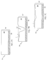
Another embodiment of the present invention is depicted in FIGS. 7A-7C. As shown, a reprogrammable e-fuse 30 can be formed using a conductive double-layer metal structure 32. In particular, a top metal layer 34 of the double-layer metal structure 32 can be formed using a metal material that is susceptible to electro-migration, while the bottom metal layer 36 of the double-layer metal structure 32 can be formed using a metal material that is much less susceptible (or not susceptible) to electro-migration. For example, since pure copper (Cu) is at least 2 to 4 times more susceptible to electro-migration than pure aluminum (Al) or certain alloys of Al, the top metal layer 34 can be formed of copper, while the bottom metal layer 36 can be formed of Al or an alloy thereof. In another embodiment of the present invention, the metal layers 34 and 36 can be reversed such that the metal material that is susceptible to electro-migration is located below the metal material that is much less susceptible (or not susceptible) to electro-migration. The metal material that is susceptible to electro-migration can also be sandwiched between layers of, or surrounded by, the metal material that is much less susceptible (or not susceptible) to electro-migration.
During programming of the e-fuse 30, as shown in FIG. 7B, a void 38 is formed in the top metal layer 34, which increases the resistance of the reprogrammable e-fuse 30 such that it is much greater than a reference resistance Rref of the e-fuse 30. During reprogramming, as shown in FIG. 7C, the void 38 is at least partially refilled and the resistance of the e-fuse 30 is reduced. Any suitable bi-layer or multi-layer metal structure can be used to form the reprogrammable e-fuse 30. The bottom metal layer 36 can also be used to provide the reference resistance Rref instead of using a barrier liner as detailed above.
A first embodiment of programming and reprogramming circuitry 40 for a reprogrammable e-fuse 10 in accordance with the present invention is depicted in FIG. 8A. During programming, the control pin “F” is set to high, so that the two nMOS devices N11 and N12 are on, but the other two nMOS devices N10 and N13 are off. A programming current with a preset current pulse height and width is applied to the e-fuse 10 from net A to net B. Similarly, during reprogramming, the control pin “F” is set to low, so that the two nMOS devices N11 and N12 are off, but the other two nMOS devices N10 and N13 are on. A reprogramming current with another preset pulse height and width is applied to the e-fuse 10 element in the opposite direction, from net B to net A.
Another embodiment of programming and reprogramming circuitry 40′ for a reprogrammable e-fuse 10 in accordance with the present invention is depicted in FIG. 8B. Here, instead of using nMOS devices for switches, any conventionally available switch such as a transmission gate device, MEMS switches, etc., can be used. In this example, four transmission gate devices T11, T12, T13, and T14 are used to program the e-fuse 10. The advantage of using transmission gate devices over nMOS device is well known in the art, and thus will not be described further. In this example, a “disable” control signal is used when the fuse programming process is finished. This will switch off the power generator 16 as well as two pull down transmission gate devices T12 and T13 so that internal nodes A and B become floating. Two OR gate devices OR1 and OR2 are used to provide forward, reverse, and enable (or disable) programming control. The circuit operation is similar to that described of FIG. 8A, except that only one power generator 16 is provided, which can be used for either forward ore reverse programming.
An illustrative sensing circuit 50 for a reprogrammable e-fuse 10 in accordance with an embodiment of the present invention is depicted in FIG. 9. As shown, the e-fuse 10 and a reference element Rref having a resistance Rref serve as the load for cross-coupled nMOS devices N1 and N2. A control pin “Sample” is used to activate the sensing operation. The “Sample” signal is tied to the gate of a PMOS device P1 and a nMOS device N3. After programming, most of the current will flow through N1 and cause node B to go “high,” since the resistance of e-fuse 10 after programming should be substantially higher than that of the reference element Rref. The final “high” state is latched in a latch register 52. On the other hand, after reprogramming, the resistance of the e-fuse 10 should be substantially lower than that of the reference element Rref, and more current will flow through N2 and cause node B to go “low.” The final “low” state is latched in the latch register 52. During programming and reprogramming, the “Sample” signal is off, so that both node A and B will be at float. Then, as shown in FIG. 8, either N12 (program) or N13 (reprogram) is on and a path to ground is provided to allow current to flow only through the e-fuse 10.
The sensing circuit 50 does not allow the reference element Rref to be shared among a plurality of e-fuses 10. If the size of the reference element Rref is relative small this approach is acceptable—a separate reference element Rref can be provided for each e-fuse 10. Otherwise, a sensing circuit 60 such as that shown in FIG. 10 can be used, where a single reference element 62 in a reference unit 64 is shared by a plurality of e-fuse units 66 (only one is shown). In sensing circuit 60, the reference unit 64 is used to generate a reference voltage equal to (Vdd−I*Rref), where I is the current flow through the reference path formed by PMOS device P51 and nMOS devices N51 and N61, and Rref is the resistance of the reference element Rref. The current I is mirrored by a shared current source 68.
Each e-fuse unit 66 includes an e-fuse 70. An identical amount of current I is mirrored via nMOS device N62. The output voltage at node B is Vdd−I*Rf, where Rf is the resistance of the e-fuse 70. A comparator 72 is formed by two PMOS devices P53 and P54, two nMOS devices N52 and N54, and a tail device N63.
The output from the reference unit 64 (node C) is tied to the gate of the nMOS device N53 and the output of the e-fuse path (node B) is tied to the gate of the nMOS device N54. After programming, Rf>Rref, and the voltage at node B is lower than at node C, so that output of the comparator 72 will go high and the high state will be latched by latch 74. Otherwise, after reprogramming, a low state will be latched by latch 74.
An illustrative physical layout of a reprogrammable e-fuse system 80 in accordance with the present invention is depicted in FIG. 11. As shown, the physical layout of the e-fuse system 80 includes a programming power and timing generator 82, a reprogramming power and timing generator 84, and a plurality of e-fuse units 86. Each e-fuse unit 86 further includes an e-fuse module 88, a sensing element 90 and a latch 92. The programming power and timing generator 82 and reprogramming power and timing generator 84 can be merged into a single unit.
As mentioned above, the use of a tapered neck region 16 facilitates the programming/reprogramming of the e-fuse 10. An analytical model illustrating the predicted electro-migration behavior in a tapered structure is presented below.
The tapered structure 100 used in this analysis is illustrated in FIG. 12. As shown, the tapered structure 100 includes first and second body regions 102, 104, and a neck region 106 that extends between the first and second body regions 102, 104. The first and second body regions 102, 104 each have a thickness of 0.5 μm, while the thickness of the neck region 106 varies from a minimum of 0.14 μm to a maximum of 0.5 μm. The taper of the neck region 106 is specified by a taper angle β. Based on the tapered structure 100, the following items were examined:
  • (A) Growth of void during forward current stressing conditions and void shrinkage during reverse current stressing conditions;
  • (B) Effects of taper geometry (β)—vary length of tapered neck region 106, keeping same minimum and maximum widths; and
  • (C) Time required to form a void and remove the void for selected void sizes (e.g., 0.125, 0.25, and 0.5 μm). The following analytic modeling assumptions were used:
  • (A) Void growth emanates from the beginning (i.e., narrowest width region) of tapered neck region 106 (no incubation time);
  • (B) Metal (e.g., Cu) removed from void is deposited at the end of tapered neck region 106;
  • (C) Metal is redeposited in the void during reverse current;
  • (D) Void growth kinetics from data on uncapped structures, T=225° C.;
  • (E) Growth velocity has exponential dependence on temperature; and
  • (F) Growth velocity has linear dependence on current density.
Based on these modeling assumptions, for a tapered neck region 106 with a length of 1.0 μm, the predicted void growth during forward current stressing (J0=70 mA/μm2 through 0.5 μm wide line) is illustrated in FIG. 13. The predicted void growth and shrinkage for a tapered neck region 1.0 μm long and with a taper angle β=10° is illustrated in FIG. 14. The predicted void growth and shrinkage for a tapered neck region 106 0.5 μm long and with a taper angle β=20° is illustrated in FIG. 15. The predicted void growth and shrinkage for a tapered neck region 2.0 μm long and with a taper angle β=5° is illustrated in FIG. 16.
From the above graphs, it can be seen that:
  • (A) Predicted electro-migration behavior in the tapered structure 100 follows asymmetric void growth and shrinkage during forward and reverse current.
  • (B) Taper Angle (β):
    • (1) Larger taper angle β increases time required to reach equivalent void size and increases nonlinearity of void growth rate.
    • (2) Total time for void growth and shrinkage is roughly equivalent.
  • (C) Time to reach equal void size is roughly proportional to current density (J).
  • (D) Strong dependence of temperature on void growth (activated process). (Joule heating not accounted for in analytical model).
FIG. 17 depicts a block diagram of a general-purpose computer system 900 that can be used to implement a reprogrammable e-fuse system, an IC including a reprogrammable e-fuse system, and the circuit design structure described herein. The design structure may be coded as a set of instructions on removable or hard media for use by the general-purpose computer 900. The computer system 900 has at least one microprocessor or central processing unit (CPU) 905. The CPU 905 is interconnected via a system bus 920 to machine readable media 975, which includes, for example, a random access memory (RAM) 910, a read-only memory (ROM) 915, a removable and/or program storage device 955, and a mass data and/or program storage device 950. An input/output (I/O) adapter 930 connects mass storage device 950 and removable storage device 955 to system bus 920. A user interface 935 connects a keyboard 965 and a mouse 960 to the system bus 920, a port adapter 925 connects a data port 945 to the system bus 920, and a display adapter 940 connect a display device 970. The ROM 915 contains the basic operating system for computer system 900. Examples of removable data and/or program storage device 955 include magnetic media such as floppy drives, tape drives, portable flash drives, zip drives, and optical media such as CD ROM or DVD drives. Examples of mass data and/or program storage device 950 include hard disk drives and non-volatile memory such as flash memory. In addition to the keyboard 965 and mouse 960, other user input devices such as trackballs, writing tablets, pressure pads, microphones, light pens and position-sensing screen displays may be connected to user interface 935. Examples of the display device 970 include cathode-ray tubes (CRT) and liquid crystal displays (LCD).
A machine readable computer program may be created by one of skill in the art and stored in computer system 900 or a data and/or any one or more of machine readable medium 975 to simplify the practicing of this invention. In operation, information for the computer program created to run the present invention is loaded on the appropriate removable data and/or program storage device 955, fed through data port 945, or entered using keyboard 965. A user controls the program by manipulating functions performed by the computer program and providing other data inputs via any of the above mentioned data input means. The display device 970 provides a way for the user to accurately control the computer program and perform the desired tasks described herein.
FIG. 18 depicts a block diagram of an example design flow 1000, which may vary depending on the type of circuit, IC, etc., being designed. For example, a design flow 1000 for building an application specific IC (ASIC) will differ from a design flow 1000 for designing a standard component. A design structure 1020 is an input to a design process 1010 and may come from an IP provider, a core developer, or other design company. The design structure 1020 comprises a circuit 100 (e.g., reprogrammable e-fuse system, IC including a reprogrammable e-fuse system, etc.) in the form of schematics or HDL, a hardware-description language, (e.g., Verilog, VHDL, C, etc.). The design structure 1020 may be on one or more of machine readable medium 975 as shown in FIG. 17. For example, the design structure 1020 may be a text file or a graphical representation of circuit 100. The design process 1010 synthesizes (or translates) the circuit 100 into a netlist 1080, where the netlist 1080 is, for example, a list of fat wires, transistors, logic gates, control circuits, I/O, models, etc., and describes the connections to other elements and circuits in an integrated circuit design and recorded on at least one machine readable medium 975.
The design process 1010 includes using a variety of inputs; for example, inputs from library elements 1030 which may house a set of commonly used elements, circuits, and devices, including models, layouts, and symbolic representations, for a given manufacturing technology (e.g., different technology nodes, 32 nm, 45 nm, 90 nm, etc.), design specifications 1040, characterization data 1050, verification data 1060, design rules 1070, and test data files 1085, which may include test patterns and other testing information. The design process 1010 further includes, for example, standard circuit design processes such as timing analysis, verification tools, design rule checkers, place and route tools, etc. One of ordinary skill in the art of integrated circuit design can appreciate the extent of possible electronic design automation tools and applications used in design process 1010 without deviating from the scope and spirit of the invention.
Ultimately, the design process 1010 translates the circuit 100, along with the rest of the integrated circuit design (if applicable), into a final design structure 1090 (e.g., information stored in a GDS storage medium). The final design structure 1090 may comprise information such as, for example, test data files, design content files, manufacturing data, layout parameters, wires, levels of metal, vias, shapes, test data, data for routing through the manufacturing line, and any other data required by a semiconductor manufacturer to produce circuit 100. The final design structure 1090 may then proceed to an output stage 1095 of design flow 1000; where output stage 1095 is, for example, where final design structure 1090: proceeds to tape-out, is released to manufacturing, is sent to another design house, or is sent back to the customer.
The foregoing description of the preferred embodiments of this invention has been presented for purposes of illustration and description. It is not intended to be exhaustive or to limit the invention to the precise form disclosed, and obviously, many modifications and variations are possible. Such modifications and variations that may be apparent to a person skilled in the art are intended to be included within the scope of this invention as defined by the accompanying claims.

Claims (17)

What is claimed is:
1. A method of configuring a destination computer system, the method comprising:
encoding code representative of a design structure embodied in a non-transitory computer readable medium of a source computer system into a set of data signals;
providing the set of data signals for use in the destination computer system distinct from the source computer system, the code representative of the design structure comprising code representing a fuse system, the code including:
instructions causing the destination computer system, upon execution of the code, to generate a representation of the fuse system, the fuse system including:
an electrically blowable fuse;
circuitry for programming the electrically blowable fuse using an electro-migration effect;
circuitry for reprogramming the electrically blowable fuse using a reverse electro-migration effect;
a reference resistance provided by a portion of the electrically blowable fuse; and
circuitry for determining a state of the electrically blowable fuse by comparing a resistance of the electrically blowable fuse to the reference resistance.
2. The method of claim 1, wherein the electrically blowable fuse comprises a tapered neck region.
3. The method of claim 1, the fuse system further comprising:
circuitry for adjusting reprogramming conditions to control a shrinkage rate of a void in a neck region of the electrically blowable fuse.
4. The method of claim 1, wherein the design structure comprises a netlist, which describes the fuse system.
5. The method of claim 1, wherein the design structure resides on storage medium as a data format used for an exchange of layout data of integrated circuits.
6. The method of claim 1, wherein the design structure includes at least one of test data files, characterization data, verification data, or design specifications.
7. A method of configuring a computer system, the method comprising:
receiving a set of data signals encoding a copy of code representative of a design structure on the computer system; and
storing the copy of the code representative of the design structure on a non-transitory computer readable medium of the computer system based on the set of data signals, the code representative of the design structure including code representing a circuit, wherein execution of the code representing the circuit causes the computer system to generate a representation of the circuit, the representation of the circuit including:
a fuse system including:
an electrically blowable fuse;
circuitry for programming the electrically blowable fuse using an electro-migration effect;
circuitry for reprogramming the electrically blowable fuse using a reverse electro-migration effect;
a reference resistance provided by a portion of the electrically blowable fuse; and
circuitry for determining a state of the electrically blowable fuse by comparing a resistance of the electrically blowable fuse to the reference resistance.
8. The method of claim 7, wherein the electrically blowable fuse comprises a tapered neck region.
9. The method of claim 7, the fuse system further comprising:
circuitry for adjusting reprogramming conditions to control a shrinkage rate of a void in a neck region of the electrically blowable fuse.
10. The method of claim 7, wherein the design structure comprises a netlist, which describes the fuse system.
11. The method of claim 7, wherein the design structure includes at least one of test data files, characterization data, verification data, or design specifications.
12. The method of claim 7, wherein the storing of the copy of the code includes executing the code on the computer system.
13. A non-transitory computer readable medium storing code representative of a design structure realized upon execution of the code by a computer system, the code representative of the design structure including code representing a circuit, the code representing the circuit comprising:
instructions causing the computer system, upon execution of the code representing the circuit, to generate a representation of the circuit, the circuit having:
an electrically blowable fuse;
circuitry for programming the electrically blowable fuse using an electro-migration effect;
circuitry for reprogramming the electrically blowable fuse using a reverse electro-migration effect;
a reference resistance provided by a portion of the electrically blowable fuse; and
circuitry for determining a state of the electrically blowable fuse by comparing a resistance of the electrically blowable fuse to the reference resistance.
14. The non-transitory computer readable medium of claim 13, wherein the electrically blowable fuse comprises a tapered neck region.
15. The non-transitory computer readable medium of claim 13, the fuse system further comprising:
circuitry for adjusting reprogramming conditions to control a shrinkage rate of a void in a neck region of the electrically blowable fuse.
16. The non-transitory computer readable medium of claim 13, wherein the design structure comprises a netlist, which describes the fuse system.
17. The non-transitory computer readable medium of claim 13, wherein the design structure includes at least one of test data files, characterization data, verification data, or design specifications.
US11/928,258 2007-10-30 2007-10-30 Reprogrammable electrical fuse Expired - Fee Related US9058887B2 (en)

Priority Applications (1)

Application Number Priority Date Filing Date Title
US11/928,258 US9058887B2 (en) 2007-10-30 2007-10-30 Reprogrammable electrical fuse

Applications Claiming Priority (1)

Application Number Priority Date Filing Date Title
US11/928,258 US9058887B2 (en) 2007-10-30 2007-10-30 Reprogrammable electrical fuse

Publications (2)

Publication Number Publication Date
US20090109722A1 US20090109722A1 (en) 2009-04-30
US9058887B2 true US9058887B2 (en) 2015-06-16

Family

ID=40582588

Family Applications (1)

Application Number Title Priority Date Filing Date
US11/928,258 Expired - Fee Related US9058887B2 (en) 2007-10-30 2007-10-30 Reprogrammable electrical fuse

Country Status (1)

Country Link
US (1) US9058887B2 (en)

Cited By (2)

* Cited by examiner, † Cited by third party
Publication number Priority date Publication date Assignee Title
US20170131342A1 (en) * 2015-11-09 2017-05-11 Toyota Motor Engineering & Manufacturing North America, Inc. Systems and methods for determining fuse loads for fuses having multiple loads from multiple sub-models
US20180323202A1 (en) * 2017-05-03 2018-11-08 International Business Machines Corporation Multiple-bit electrical fuses

Families Citing this family (5)

* Cited by examiner, † Cited by third party
Publication number Priority date Publication date Assignee Title
US7479324B2 (en) * 2005-11-08 2009-01-20 Saint-Gobain Ceramics & Plastics, Inc. Pigments comprising alumina hydrate and a dye, and polymer composites formed thereof
US7956466B2 (en) * 2008-05-09 2011-06-07 International Business Machines Corporation Structure for interconnect structure containing various capping materials for electrical fuse and other related applications
US8772156B2 (en) * 2008-05-09 2014-07-08 International Business Machines Corporation Methods of fabricating interconnect structures containing various capping materials for electrical fuse and other related applications
US9372226B2 (en) * 2014-07-22 2016-06-21 Globalfoundries Inc. Wafer test structures and methods of providing wafer test structures
CN105470238A (en) * 2014-09-09 2016-04-06 中芯国际集成电路制造(上海)有限公司 Electrical programmable fuse device, integrated circuit and electronic device

Citations (36)

* Cited by examiner, † Cited by third party
Publication number Priority date Publication date Assignee Title
US3717852A (en) * 1971-09-17 1973-02-20 Ibm Electronically rewritable read-only memory using via connections
US4420766A (en) * 1981-02-09 1983-12-13 Harris Corporation Reversibly programmable polycrystalline silicon memory element
US5412593A (en) 1994-01-12 1995-05-02 Texas Instruments Incorporated Fuse and antifuse reprogrammable link for integrated circuits
US5465004A (en) 1989-08-18 1995-11-07 North American Philips Corporation Programmable semiconductor integrated circuits having fusible links
US5536968A (en) 1992-12-18 1996-07-16 At&T Global Information Solutions Company Polysilicon fuse array structure for integrated circuits
CN1202277A (en) 1995-09-29 1998-12-16 英特尔公司 Silicide agglomeration fuse device
US20010013114A1 (en) * 1998-11-11 2001-08-09 Laberge Paul A. Placing gates in an integrated circuit based upon drive strength
US6323535B1 (en) 2000-06-16 2001-11-27 Infineon Technologies North America Corp. Electrical fuses employing reverse biasing to enhance programming
US20020032619A1 (en) * 2000-05-01 2002-03-14 Pozo Jose Luis Method and system for selecting fuse configurations
US20020110033A1 (en) 2001-02-13 2002-08-15 Micron Technology, Inc. Programmable fuse and antifuse and method therefor
US6436585B1 (en) 2000-02-25 2002-08-20 International Business Machines Corporation Method of using optical proximity effects to create electrically blown fuses with sub-critical dimension neck downs
US6548358B2 (en) 1998-06-08 2003-04-15 International Business Machines Corporation Electrically blowable fuse with reduced cross-sectional area
US6624499B2 (en) * 2002-02-28 2003-09-23 Infineon Technologies Ag System for programming fuse structure by electromigration of silicide enhanced by creating temperature gradient
US20030206429A2 (en) * 1998-11-16 2003-11-06 Matrix Semiconductor, Inc. Vertically stacked field programmable nonvolatile memory and method of fabrication
US20050167728A1 (en) 2004-01-29 2005-08-04 Chandrasekharan Kothandaraman Single-poly 2-transistor based fuse element
US7110313B2 (en) * 2005-01-04 2006-09-19 Taiwan Semiconductor Manufacturing Company, Ltd. Multiple-time electrical fuse programming circuit
US7153712B1 (en) * 2003-10-16 2006-12-26 Altera Corporation Electrically-programmable integrated circuit fuses and sensing circuits
US7200064B1 (en) * 2005-10-07 2007-04-03 International Business Machines Corporation Apparatus and method for providing a reprogrammable electrically programmable fuse
US20070099326A1 (en) * 2005-11-03 2007-05-03 International Business Machines Corporation eFuse and methods of manufacturing the same
US7224633B1 (en) * 2005-12-08 2007-05-29 International Business Machines Corporation eFuse sense circuit
US7242239B2 (en) * 2005-06-07 2007-07-10 International Business Machines Corporation Programming and determining state of electrical fuse using field effect transistor having multiple conduction states
US7268577B2 (en) * 2004-12-17 2007-09-11 International Business Machines Corporation Changing chip function based on fuse states
US7298639B2 (en) * 2005-05-04 2007-11-20 International Business Machines Corporation Reprogrammable electrical fuse
US20070290233A1 (en) * 2005-06-14 2007-12-20 International Business Machines Corp. Reprogrammable Fuse Structure and Method
US20070300200A1 (en) * 2006-06-26 2007-12-27 Advanced Micro Devices, Inc. Integrated circuit design system
US20080029843A1 (en) * 2006-05-11 2008-02-07 International Business Machines Corporation E-Fuse and Method for Fabricating E-Fuses Integrating Polysilicon Resistor Masks
US20080106323A1 (en) * 2006-10-19 2008-05-08 Anthony Gus Aipperspach Electrically Programmable Fuse Sense Circuit
US20080143373A1 (en) * 2004-12-17 2008-06-19 Bonaccio Anthony R Using electrically programmable fuses to hide architecture, prevent reverse engineering, and make a device inoperable
US7394089B2 (en) * 2006-08-25 2008-07-01 International Business Machines Corporation Heat-shielded low power PCM-based reprogrammable EFUSE device
US20080157851A1 (en) * 2006-10-19 2008-07-03 International Business Machines Corporation Electrically Programmable Fuse Sense Circuit
US20080217736A1 (en) * 2007-03-07 2008-09-11 International Business Machines Corporation Electrical antifuse, method of manufacture and method of programming
US20080283963A1 (en) * 2007-05-15 2008-11-20 Taiwan Semiconductor Manufacturing Co., Ltd. Electrical Fuse Circuit for Security Applications
US20080315353A1 (en) * 2007-06-25 2008-12-25 International Business Machines Corporation Empty vias for electromigration during electronic-fuse re-programming
US20090042341A1 (en) * 2007-08-08 2009-02-12 International Business Machines Corporation Electrical fuse with a thinned fuselink middle portion
US7557424B2 (en) * 2007-01-03 2009-07-07 International Business Machines Corporation Reversible electric fuse and antifuse structures for semiconductor devices
US20090179302A1 (en) * 2004-10-21 2009-07-16 International Business Machines Corporation Programmable electronic fuse

Patent Citations (46)

* Cited by examiner, † Cited by third party
Publication number Priority date Publication date Assignee Title
US3717852A (en) * 1971-09-17 1973-02-20 Ibm Electronically rewritable read-only memory using via connections
US4420766A (en) * 1981-02-09 1983-12-13 Harris Corporation Reversibly programmable polycrystalline silicon memory element
US5465004A (en) 1989-08-18 1995-11-07 North American Philips Corporation Programmable semiconductor integrated circuits having fusible links
US5536968A (en) 1992-12-18 1996-07-16 At&T Global Information Solutions Company Polysilicon fuse array structure for integrated circuits
US5412593A (en) 1994-01-12 1995-05-02 Texas Instruments Incorporated Fuse and antifuse reprogrammable link for integrated circuits
CN1202277A (en) 1995-09-29 1998-12-16 英特尔公司 Silicide agglomeration fuse device
US6548358B2 (en) 1998-06-08 2003-04-15 International Business Machines Corporation Electrically blowable fuse with reduced cross-sectional area
US20010013114A1 (en) * 1998-11-11 2001-08-09 Laberge Paul A. Placing gates in an integrated circuit based upon drive strength
US20030206429A2 (en) * 1998-11-16 2003-11-06 Matrix Semiconductor, Inc. Vertically stacked field programmable nonvolatile memory and method of fabrication
US6436585B1 (en) 2000-02-25 2002-08-20 International Business Machines Corporation Method of using optical proximity effects to create electrically blown fuses with sub-critical dimension neck downs
US20020032619A1 (en) * 2000-05-01 2002-03-14 Pozo Jose Luis Method and system for selecting fuse configurations
US6323535B1 (en) 2000-06-16 2001-11-27 Infineon Technologies North America Corp. Electrical fuses employing reverse biasing to enhance programming
US20020110033A1 (en) 2001-02-13 2002-08-15 Micron Technology, Inc. Programmable fuse and antifuse and method therefor
US6624499B2 (en) * 2002-02-28 2003-09-23 Infineon Technologies Ag System for programming fuse structure by electromigration of silicide enhanced by creating temperature gradient
US7153712B1 (en) * 2003-10-16 2006-12-26 Altera Corporation Electrically-programmable integrated circuit fuses and sensing circuits
US20050167728A1 (en) 2004-01-29 2005-08-04 Chandrasekharan Kothandaraman Single-poly 2-transistor based fuse element
US7075127B2 (en) 2004-01-29 2006-07-11 Infineon Technologies Ag Single-poly 2-transistor based fuse element
US20090179302A1 (en) * 2004-10-21 2009-07-16 International Business Machines Corporation Programmable electronic fuse
US7550789B2 (en) * 2004-12-17 2009-06-23 International Business Machines Corporation Using electrically programmable fuses to hide architecture, prevent reverse engineering, and make a device inoperable
US7442583B2 (en) * 2004-12-17 2008-10-28 International Business Machines Corporation Using electrically programmable fuses to hide architecture, prevent reverse engineering, and make a device inoperable
US20080143373A1 (en) * 2004-12-17 2008-06-19 Bonaccio Anthony R Using electrically programmable fuses to hide architecture, prevent reverse engineering, and make a device inoperable
US7336095B2 (en) * 2004-12-17 2008-02-26 International Business Machines Corporation Changing chip function based on fuse states
US7268577B2 (en) * 2004-12-17 2007-09-11 International Business Machines Corporation Changing chip function based on fuse states
US20070241768A1 (en) * 2004-12-17 2007-10-18 Erickson Karl R Changing chip function based on fuse states
US7110313B2 (en) * 2005-01-04 2006-09-19 Taiwan Semiconductor Manufacturing Company, Ltd. Multiple-time electrical fuse programming circuit
US7298639B2 (en) * 2005-05-04 2007-11-20 International Business Machines Corporation Reprogrammable electrical fuse
US7242239B2 (en) * 2005-06-07 2007-07-10 International Business Machines Corporation Programming and determining state of electrical fuse using field effect transistor having multiple conduction states
US20070290233A1 (en) * 2005-06-14 2007-12-20 International Business Machines Corp. Reprogrammable Fuse Structure and Method
US7388273B2 (en) * 2005-06-14 2008-06-17 International Business Machines Corporation Reprogrammable fuse structure and method
US20070081406A1 (en) * 2005-10-07 2007-04-12 Boerstler David W Apparatus and method for providing a reprogrammable electrically programmable fuse
US7200064B1 (en) * 2005-10-07 2007-04-03 International Business Machines Corporation Apparatus and method for providing a reprogrammable electrically programmable fuse
US7659168B2 (en) * 2005-11-03 2010-02-09 International Business Machines Corporation eFuse and methods of manufacturing the same
US20070099326A1 (en) * 2005-11-03 2007-05-03 International Business Machines Corporation eFuse and methods of manufacturing the same
US7224633B1 (en) * 2005-12-08 2007-05-29 International Business Machines Corporation eFuse sense circuit
US20080029843A1 (en) * 2006-05-11 2008-02-07 International Business Machines Corporation E-Fuse and Method for Fabricating E-Fuses Integrating Polysilicon Resistor Masks
US20070300200A1 (en) * 2006-06-26 2007-12-27 Advanced Micro Devices, Inc. Integrated circuit design system
US20080224118A1 (en) * 2006-08-25 2008-09-18 International Business Machines Corporation Heat-shielded low power pcm-based reprogrammable efuse device
US7394089B2 (en) * 2006-08-25 2008-07-01 International Business Machines Corporation Heat-shielded low power PCM-based reprogrammable EFUSE device
US20080157851A1 (en) * 2006-10-19 2008-07-03 International Business Machines Corporation Electrically Programmable Fuse Sense Circuit
US20080106323A1 (en) * 2006-10-19 2008-05-08 Anthony Gus Aipperspach Electrically Programmable Fuse Sense Circuit
US7557424B2 (en) * 2007-01-03 2009-07-07 International Business Machines Corporation Reversible electric fuse and antifuse structures for semiconductor devices
US20080217736A1 (en) * 2007-03-07 2008-09-11 International Business Machines Corporation Electrical antifuse, method of manufacture and method of programming
US20090321735A1 (en) * 2007-03-07 2009-12-31 Alberto Cestero Electrical Antifuse and Method of Programming
US20080283963A1 (en) * 2007-05-15 2008-11-20 Taiwan Semiconductor Manufacturing Co., Ltd. Electrical Fuse Circuit for Security Applications
US20080315353A1 (en) * 2007-06-25 2008-12-25 International Business Machines Corporation Empty vias for electromigration during electronic-fuse re-programming
US20090042341A1 (en) * 2007-08-08 2009-02-12 International Business Machines Corporation Electrical fuse with a thinned fuselink middle portion

Non-Patent Citations (11)

* Cited by examiner, † Cited by third party
Title
E. Castano, et al., "In situ observations of dc and ac electromigration in passivated A1 lines", Appl. Phys. Lett. 59 (1), Jul. 1, 1991, pp. 129-131, American Institute of Physics.
Gebreselasie, E.G., et al., "electrically programmable fuses for analog and mixed signal applications in silicon germanium BiCMOS technologies", 2007, IBM Microelectronics, IBM BCTM 16.1, pp. 238-241. *
Jiang Tao et al., "An Electromigration Failure Model for Interconnects Under Pulsed and Bidirectional Current Stressing," IEEE Transactions on Electron Devices, vol. 41, No. 4, Apr. 1994, pp. 539-545.
Kothandaaman, C. et al.,"Electrically programmalbe fuse (eFUSE) using electromigration in silicides", Sep. 2002, IEEE. pages 523-525. *
U.S. Appl. No. 10/908,245, filed May 4, 2005, Notice of Allowance and Fees Due dated Jul. 16, 2007.
U.S. Appl. No. 10/908,245, filed May 4, 2005, Office Action dated May 8, 2007.
U.S. Appl. No. 11/834,841, filed Aug. 7, 2007, Notice of Abandonment dated Mar. 31, 2010.
U.S. Appl. No. 11/834,841, filed Aug. 7, 2007, Office Action dated Dec. 4, 2008.
U.S. Appl. No. 11/834,841, filed Aug. 7, 2007, Office Action dated Mar. 19, 2009.
U.S. Appl. No. 11/834,841, filed Aug. 7, 2007, Office Action dated Sep. 11, 2009.
Unknown, "Information Disclosure Statement," IBM China Ltd, Jul. 25, 2008, in 2 pages.

Cited By (6)

* Cited by examiner, † Cited by third party
Publication number Priority date Publication date Assignee Title
US20170131342A1 (en) * 2015-11-09 2017-05-11 Toyota Motor Engineering & Manufacturing North America, Inc. Systems and methods for determining fuse loads for fuses having multiple loads from multiple sub-models
US10054629B2 (en) * 2015-11-09 2018-08-21 Toyota Motor Engineering & Manufacturing North America, Inc. Systems and methods for determining fuse loads for fuses having multiple loads from multiple sub-models
US20180323202A1 (en) * 2017-05-03 2018-11-08 International Business Machines Corporation Multiple-bit electrical fuses
US20180323203A1 (en) * 2017-05-03 2018-11-08 International Business Machines Corporation Multiple-bit electrical fuses
US10141320B1 (en) * 2017-05-03 2018-11-27 International Business Machines Corporation Multiple-bit electrical fuses
US10586799B2 (en) * 2017-05-03 2020-03-10 International Business Machines Corporation Multiple-bit electrical fuses

Also Published As

Publication number Publication date
US20090109722A1 (en) 2009-04-30

Similar Documents

Publication Publication Date Title
US7298639B2 (en) Reprogrammable electrical fuse
US9058887B2 (en) Reprogrammable electrical fuse
US7609577B2 (en) Design structure for improving sensing margin of electrically programmable fuses
US20070298526A1 (en) Programmable semiconductor device
JP4659119B2 (en) A method to provide optimal field programming of electronic fuses.
US7636268B1 (en) Integrated circuit with improved static noise margin
US20200082051A1 (en) Standard cell design system, standard cell design optimization method thereof, and semiconductor design system
US20090002119A1 (en) Fuse sensing scheme
US11030383B2 (en) Integrated device and method of forming the same
US20140253220A1 (en) Electronic fuse cell and array
US20230252219A1 (en) Method and system of forming semiconductor device
US7915949B2 (en) Implementing eFuse resistance determination before initiating eFuse blow
US7532057B2 (en) Electrically programmable fuse sense circuit
TW201842456A (en) Computationally efficient nano-scale conductor resistance model
CN113204931A (en) Method for generating circuit layout
TW201826155A (en) Integrated circuits, computer-implemented method of manufacturing the same, and standard cell defining the same
Wang Reliability analysis of spintronic device based logic and memory circuits
Xie et al. On the robustness of memristor based logic gates
US20080169843A1 (en) Method and Apparatus for Implementing Efuse Sense Amplifier Testing Without Blowing the Efuse
JP5480375B2 (en) Circuit structure and method for programming and reprogramming low power multi-state electronic fuses (e fuses)
US20230062482A1 (en) Systems, Devices, and Methods for Dedicated Low Temperature Design and Operation
US7757200B2 (en) Structure of an apparatus for programming an electronically programmable semiconductor fuse
US7830171B1 (en) Method and apparatus for initializing an integrated circuit
Bruchon et al. Magnetic tunnelling junction based FPGA
Brum et al. Magpdk: An open-source process design kit for circuit design with magnetic tunnel junctions

Legal Events

Date Code Title Description
AS Assignment

Owner name: INTERNATIONAL BUSINESS MACHINES CORPORATION, NEW Y

Free format text: ASSIGNMENT OF ASSIGNORS INTEREST;ASSIGNORS:HSU, LOUIS C.;MURRAY, CONAL E.;NARAYAN, CHANDRASEKHAR;AND OTHERS;REEL/FRAME:020116/0657;SIGNING DATES FROM 20071012 TO 20071029

Owner name: INTERNATIONAL BUSINESS MACHINES CORPORATION, NEW Y

Free format text: ASSIGNMENT OF ASSIGNORS INTEREST;ASSIGNORS:HSU, LOUIS C.;MURRAY, CONAL E.;NARAYAN, CHANDRASEKHAR;AND OTHERS;SIGNING DATES FROM 20071012 TO 20071029;REEL/FRAME:020116/0657

STCF Information on status: patent grant

Free format text: PATENTED CASE

FEPP Fee payment procedure

Free format text: MAINTENANCE FEE REMINDER MAILED (ORIGINAL EVENT CODE: REM.); ENTITY STATUS OF PATENT OWNER: LARGE ENTITY

LAPS Lapse for failure to pay maintenance fees

Free format text: PATENT EXPIRED FOR FAILURE TO PAY MAINTENANCE FEES (ORIGINAL EVENT CODE: EXP.); ENTITY STATUS OF PATENT OWNER: LARGE ENTITY

STCH Information on status: patent discontinuation

Free format text: PATENT EXPIRED DUE TO NONPAYMENT OF MAINTENANCE FEES UNDER 37 CFR 1.362

FP Lapsed due to failure to pay maintenance fee

Effective date: 20190616