US9052490B2 - Braided fiber optic cross-connect switches - Google Patents
Braided fiber optic cross-connect switches Download PDFInfo
- Publication number
- US9052490B2 US9052490B2 US13/908,115 US201313908115A US9052490B2 US 9052490 B2 US9052490 B2 US 9052490B2 US 201313908115 A US201313908115 A US 201313908115A US 9052490 B2 US9052490 B2 US 9052490B2
- Authority
- US
- United States
- Prior art keywords
- reel
- optical fiber
- fiber
- column
- circuit
- Prior art date
- Legal status (The legal status is an assumption and is not a legal conclusion. Google has not performed a legal analysis and makes no representation as to the accuracy of the status listed.)
- Active - Reinstated
Links
- 239000000835 fiber Substances 0.000 title claims abstract description 175
- 239000013307 optical fiber Substances 0.000 claims abstract description 64
- 230000033001 locomotion Effects 0.000 claims description 14
- 239000011159 matrix material Substances 0.000 claims description 13
- 239000000758 substrate Substances 0.000 claims description 4
- 230000000712 assembly Effects 0.000 claims description 3
- 238000000429 assembly Methods 0.000 claims description 3
- 239000000700 radioactive tracer Substances 0.000 claims description 2
- 238000000034 method Methods 0.000 abstract description 47
- 230000003287 optical effect Effects 0.000 abstract description 19
- 230000001427 coherent effect Effects 0.000 abstract description 11
- 230000008569 process Effects 0.000 description 32
- 238000003032 molecular docking Methods 0.000 description 27
- 238000004422 calculation algorithm Methods 0.000 description 14
- 239000013598 vector Substances 0.000 description 14
- 238000013459 approach Methods 0.000 description 12
- 230000007723 transport mechanism Effects 0.000 description 12
- 239000013305 flexible fiber Substances 0.000 description 9
- 230000036961 partial effect Effects 0.000 description 9
- 230000000903 blocking effect Effects 0.000 description 8
- 238000003780 insertion Methods 0.000 description 8
- 230000037431 insertion Effects 0.000 description 8
- 230000007246 mechanism Effects 0.000 description 8
- 238000013519 translation Methods 0.000 description 8
- 230000014616 translation Effects 0.000 description 8
- 238000010586 diagram Methods 0.000 description 6
- 238000004364 calculation method Methods 0.000 description 5
- 230000008859 change Effects 0.000 description 5
- 230000000875 corresponding effect Effects 0.000 description 5
- 230000003247 decreasing effect Effects 0.000 description 5
- 230000002452 interceptive effect Effects 0.000 description 5
- 238000007726 management method Methods 0.000 description 5
- 238000004088 simulation Methods 0.000 description 5
- 230000001174 ascending effect Effects 0.000 description 4
- 238000004140 cleaning Methods 0.000 description 4
- 239000004744 fabric Substances 0.000 description 4
- 239000000463 material Substances 0.000 description 4
- 230000013011 mating Effects 0.000 description 4
- 238000012544 monitoring process Methods 0.000 description 4
- 230000002829 reductive effect Effects 0.000 description 4
- 230000000717 retained effect Effects 0.000 description 4
- 239000000725 suspension Substances 0.000 description 4
- 238000005452 bending Methods 0.000 description 3
- 230000008901 benefit Effects 0.000 description 3
- 230000009977 dual effect Effects 0.000 description 3
- 238000005516 engineering process Methods 0.000 description 3
- 238000011084 recovery Methods 0.000 description 3
- 238000003860 storage Methods 0.000 description 3
- 238000009941 weaving Methods 0.000 description 3
- 239000004677 Nylon Substances 0.000 description 2
- 239000004696 Poly ether ether ketone Substances 0.000 description 2
- 229920002614 Polyether block amide Polymers 0.000 description 2
- 238000010923 batch production Methods 0.000 description 2
- JUPQTSLXMOCDHR-UHFFFAOYSA-N benzene-1,4-diol;bis(4-fluorophenyl)methanone Chemical compound OC1=CC=C(O)C=C1.C1=CC(F)=CC=C1C(=O)C1=CC=C(F)C=C1 JUPQTSLXMOCDHR-UHFFFAOYSA-N 0.000 description 2
- 230000005540 biological transmission Effects 0.000 description 2
- 238000010276 construction Methods 0.000 description 2
- 230000008878 coupling Effects 0.000 description 2
- 238000010168 coupling process Methods 0.000 description 2
- 238000005859 coupling reaction Methods 0.000 description 2
- 230000001419 dependent effect Effects 0.000 description 2
- 238000009826 distribution Methods 0.000 description 2
- 229920001971 elastomer Polymers 0.000 description 2
- 238000005304 joining Methods 0.000 description 2
- 229910052751 metal Inorganic materials 0.000 description 2
- 239000002184 metal Substances 0.000 description 2
- 229920001778 nylon Polymers 0.000 description 2
- 238000005457 optimization Methods 0.000 description 2
- 239000004033 plastic Substances 0.000 description 2
- 229920003023 plastic Polymers 0.000 description 2
- 229920002530 polyetherether ketone Polymers 0.000 description 2
- -1 polypropylene Polymers 0.000 description 2
- 239000004810 polytetrafluoroethylene Substances 0.000 description 2
- 229920001343 polytetrafluoroethylene Polymers 0.000 description 2
- 229920002635 polyurethane Polymers 0.000 description 2
- 239000004814 polyurethane Substances 0.000 description 2
- 229920003051 synthetic elastomer Polymers 0.000 description 2
- 238000012360 testing method Methods 0.000 description 2
- 229920000049 Carbon (fiber) Polymers 0.000 description 1
- RYGMFSIKBFXOCR-UHFFFAOYSA-N Copper Chemical compound [Cu] RYGMFSIKBFXOCR-UHFFFAOYSA-N 0.000 description 1
- 229920002943 EPDM rubber Polymers 0.000 description 1
- 101100351735 Neurospora crassa (strain ATCC 24698 / 74-OR23-1A / CBS 708.71 / DSM 1257 / FGSC 987) ptr-4 gene Proteins 0.000 description 1
- CBENFWSGALASAD-UHFFFAOYSA-N Ozone Chemical compound [O-][O+]=O CBENFWSGALASAD-UHFFFAOYSA-N 0.000 description 1
- 101150070307 PFA4 gene Proteins 0.000 description 1
- 239000004698 Polyethylene Substances 0.000 description 1
- 239000004743 Polypropylene Substances 0.000 description 1
- 229910000831 Steel Inorganic materials 0.000 description 1
- 238000005299 abrasion Methods 0.000 description 1
- 230000004075 alteration Effects 0.000 description 1
- 229910052782 aluminium Inorganic materials 0.000 description 1
- XAGFODPZIPBFFR-UHFFFAOYSA-N aluminium Chemical compound [Al] XAGFODPZIPBFFR-UHFFFAOYSA-N 0.000 description 1
- 238000003491 array Methods 0.000 description 1
- 230000003190 augmentative effect Effects 0.000 description 1
- 235000000332 black box Nutrition 0.000 description 1
- 239000004917 carbon fiber Substances 0.000 description 1
- 238000004891 communication Methods 0.000 description 1
- 239000002131 composite material Substances 0.000 description 1
- 239000004020 conductor Substances 0.000 description 1
- 238000012790 confirmation Methods 0.000 description 1
- 239000000470 constituent Substances 0.000 description 1
- 229910052802 copper Inorganic materials 0.000 description 1
- 239000010949 copper Substances 0.000 description 1
- 230000002596 correlated effect Effects 0.000 description 1
- 230000001186 cumulative effect Effects 0.000 description 1
- 230000000694 effects Effects 0.000 description 1
- 230000001747 exhibiting effect Effects 0.000 description 1
- 239000012634 fragment Substances 0.000 description 1
- 239000002783 friction material Substances 0.000 description 1
- 230000005484 gravity Effects 0.000 description 1
- 238000003384 imaging method Methods 0.000 description 1
- 238000007689 inspection Methods 0.000 description 1
- 238000009434 installation Methods 0.000 description 1
- 229920000126 latex Polymers 0.000 description 1
- 230000000670 limiting effect Effects 0.000 description 1
- 238000012423 maintenance Methods 0.000 description 1
- 230000014759 maintenance of location Effects 0.000 description 1
- 238000013507 mapping Methods 0.000 description 1
- VNWKTOKETHGBQD-UHFFFAOYSA-N methane Chemical compound C VNWKTOKETHGBQD-UHFFFAOYSA-N 0.000 description 1
- 238000002156 mixing Methods 0.000 description 1
- 238000012986 modification Methods 0.000 description 1
- 230000004048 modification Effects 0.000 description 1
- 239000002991 molded plastic Substances 0.000 description 1
- 229920003052 natural elastomer Polymers 0.000 description 1
- 229920001194 natural rubber Polymers 0.000 description 1
- 239000003921 oil Substances 0.000 description 1
- 238000003909 pattern recognition Methods 0.000 description 1
- 229920000573 polyethylene Polymers 0.000 description 1
- 229920001155 polypropylene Polymers 0.000 description 1
- 229920000915 polyvinyl chloride Polymers 0.000 description 1
- 238000004321 preservation Methods 0.000 description 1
- 230000008707 rearrangement Effects 0.000 description 1
- 150000003839 salts Chemical class 0.000 description 1
- 230000008054 signal transmission Effects 0.000 description 1
- 239000007787 solid Substances 0.000 description 1
- 229910001220 stainless steel Inorganic materials 0.000 description 1
- 239000010935 stainless steel Substances 0.000 description 1
- 239000010959 steel Substances 0.000 description 1
- 230000001360 synchronised effect Effects 0.000 description 1
- XLYOFNOQVPJJNP-UHFFFAOYSA-N water Substances O XLYOFNOQVPJJNP-UHFFFAOYSA-N 0.000 description 1
- 238000004804 winding Methods 0.000 description 1
- 239000002759 woven fabric Substances 0.000 description 1
Images


Classifications
-
- G—PHYSICS
- G02—OPTICS
- G02B—OPTICAL ELEMENTS, SYSTEMS OR APPARATUS
- G02B6/00—Light guides; Structural details of arrangements comprising light guides and other optical elements, e.g. couplings
- G02B6/24—Coupling light guides
- G02B6/26—Optical coupling means
- G02B6/35—Optical coupling means having switching means
- G02B6/3502—Optical coupling means having switching means involving direct waveguide displacement, e.g. cantilever type waveguide displacement involving waveguide bending, or displacing an interposed waveguide between stationary waveguides
-
- G—PHYSICS
- G02—OPTICS
- G02B—OPTICAL ELEMENTS, SYSTEMS OR APPARATUS
- G02B6/00—Light guides; Structural details of arrangements comprising light guides and other optical elements, e.g. couplings
- G02B6/24—Coupling light guides
- G02B6/26—Optical coupling means
- G02B6/35—Optical coupling means having switching means
- G02B6/3564—Mechanical details of the actuation mechanism associated with the moving element or mounting mechanism details
-
- G—PHYSICS
- G02—OPTICS
- G02B—OPTICAL ELEMENTS, SYSTEMS OR APPARATUS
- G02B6/00—Light guides; Structural details of arrangements comprising light guides and other optical elements, e.g. couplings
- G02B6/44—Mechanical structures for providing tensile strength and external protection for fibres, e.g. optical transmission cables
- G02B6/4439—Auxiliary devices
- G02B6/444—Systems or boxes with surplus lengths
- G02B6/4452—Distribution frames
-
- G—PHYSICS
- G02—OPTICS
- G02B—OPTICAL ELEMENTS, SYSTEMS OR APPARATUS
- G02B6/00—Light guides; Structural details of arrangements comprising light guides and other optical elements, e.g. couplings
- G02B6/44—Mechanical structures for providing tensile strength and external protection for fibres, e.g. optical transmission cables
- G02B6/4439—Auxiliary devices
- G02B6/444—Systems or boxes with surplus lengths
- G02B6/44528—Patch-cords; Connector arrangements in the system or in the box
-
- G—PHYSICS
- G02—OPTICS
- G02B—OPTICAL ELEMENTS, SYSTEMS OR APPARATUS
- G02B6/00—Light guides; Structural details of arrangements comprising light guides and other optical elements, e.g. couplings
- G02B6/44—Mechanical structures for providing tensile strength and external protection for fibres, e.g. optical transmission cables
- G02B6/4439—Auxiliary devices
- G02B6/4457—Bobbins; Reels
- G02B6/4458—Coiled, e.g. extensible helix
-
- G—PHYSICS
- G02—OPTICS
- G02B—OPTICAL ELEMENTS, SYSTEMS OR APPARATUS
- G02B6/00—Light guides; Structural details of arrangements comprising light guides and other optical elements, e.g. couplings
- G02B6/24—Coupling light guides
- G02B6/36—Mechanical coupling means
- G02B6/38—Mechanical coupling means having fibre to fibre mating means
- G02B6/3807—Dismountable connectors, i.e. comprising plugs
- G02B6/3897—Connectors fixed to housings, casing, frames or circuit boards
-
- G—PHYSICS
- G02—OPTICS
- G02B—OPTICAL ELEMENTS, SYSTEMS OR APPARATUS
- G02B6/00—Light guides; Structural details of arrangements comprising light guides and other optical elements, e.g. couplings
- G02B6/44—Mechanical structures for providing tensile strength and external protection for fibres, e.g. optical transmission cables
- G02B6/4439—Auxiliary devices
- G02B6/444—Systems or boxes with surplus lengths
- G02B6/4452—Distribution frames
- G02B6/44524—Distribution frames with frame parts or auxiliary devices mounted on the frame and collectively not covering a whole width of the frame or rack
-
- G—PHYSICS
- G02—OPTICS
- G02B—OPTICAL ELEMENTS, SYSTEMS OR APPARATUS
- G02B6/00—Light guides; Structural details of arrangements comprising light guides and other optical elements, e.g. couplings
- G02B6/44—Mechanical structures for providing tensile strength and external protection for fibres, e.g. optical transmission cables
- G02B6/4439—Auxiliary devices
- G02B6/4457—Bobbins; Reels
Definitions
- This invention relates to reconfigurable fiber optic cross-connect systems, and more particularly, to apparatus, systems and methods to reconfigure flexible fiber circuits at a rapid rate within a volume shared by large numbers of adjacent and intermixed fiber circuits.
- Fiber optic cross-connects and patch-panels are used to terminate large numbers of optical fibers at an array of connectors, providing a central location to manually or semi-manually interconnect network devices with patchcords.
- Typical cross-connect systems interconnect 100 to 10,000 network devices with complete flexibility. Connections between various types of transmission equipment, such as transceivers, amplifiers, switches and to outside plant cables destined for other exchanges, local offices, central offices, optical line terminations and points-of-presence are configured by manually installing jumpers to create communication links between specified pairs of ports.
- FTTH Fiber-to-the-Home
- access networks for example, the deployment of cross-connects are geographically dispersed and the number of ports is increasing significantly. Consequently, the tasks of allocating, reconfiguring and testing a fiber circuit within the network is challenging. There is significant potential for errors or damage resulting from manual changes to the physical network configuration. There is a need to automate the highly manual process of managing physical interconnections.
- Robotically reconfigurable cross-connects can reduce the operational and maintenance costs of the network, improve the delivery of new services to customers and leverage costly test and diagnostic equipment by switching or sharing it across the entire network. It is appealing from a cost, accuracy and response-time perspective to configure the cross-connect from a remote network management center through network management software.
- the key building block of an automated patch-panel system is a scalable, high port count, all-optical cross-connect switch.
- Robotic cross-connect approaches have the potential to perform substantially better from the standpoint of optical performance and maintain signal transmission even in the absence of electrical power.
- the scalability of these prior art robotic versions has been limited.
- the footprint of these versions scales as N 2 , where N is the number of circuits.
- N is the number of circuits.
- Automated fiber optic patch panels demand scalability to port counts in excess of 1000 within the footprint of a manual patch panel, modularity and the ability to incrementally add circuits on an as-needed basis.
- Current technologies have been unable to achieve these varied requirements.
- a system of fiber optic strands extends between changeable terminals disposed in a two-dimensional planar matrix and a fixed linear assembly of points at a mid-span portion along the strands, each strand having unique addresses in the matrix and linear assembly planes.
- the gaps between vertical columns in the two-dimensional matrix are sized to permit transport of a gripper mechanism therebetween.
- the rows of input terminals in the two-dimensional matrix are shiftable in either direction transverse to the columns by a clearance increment adequate to permit passage of the transport mechanism and a selected strand therebetween.
- This fiber optic cross-connect system thus utilizes a multiplicity of fiber optic strands disposed in a spatially coherent configuration with interconnections having different path lengths between a fixed configuration of strand guides parallel to one axis at one plane and interconnected to variable positions along a second two-dimensional plane.
- a modular, expandable system of rotatable reels enables the interconnections at the plane of the two-dimensional matrix to be varied while maintaining tension and more than a minimum radius of curvature on the optical fiber strands.
- the disclosed fiber optic cross-connect system thus establishes arbitrary, low loss optical links between a multiplicity of input connections and a multiplicity of output connections, joined by continuous lengths of low loss, flexible optical waveguides defining vectors therebetween.
- Input connections are disposed in a regularly spaced, two-dimensional array coincident within a plane, the array having a number of original columns N and a number of rows M, wherein the array of input connections are in a dynamic geometric relation to one another to temporarily, reversibly and repeatedly transform to an array with N+1 partially filled columns and M rows.
- a method of and apparatus for dynamically reconfiguring a fiber optic interconnection within an interconnect volume including a large number of spatially coherent fiber optic interconnections defining vectors and spanning a regular two-dimensional array of inputs and ordered outputs are disclosed.
- Robotic manipulation of an affected optical fiber surrounded by a multiplicity of unaffected optical fibers is performed by traversing the unaffected optical fibers in alternating positive and negative interweaves with both column traversals and transverse row shifting alternating in direction as commanded, forming a multiplicity of separate, strictly positive or negative non-repeating subbraids.
- the robotic manipulation trajectory passes individually through one or more of the subbraids defining a column by programmed splitting of the subbraids into two partial sub-subbraids.
- the splitting is adequate for non-interfering passage of the affected fiber through the split in the subbraid.
- the two partial subbraids are then merged after the passage by affected fiber is complete. This interweaving concept materially reduces the time needed for reconfiguration.
- Systems and methods in accordance with the invention include numerous features that facilitate assembly and operation of the reconfiguration system. Length variations in the fiber optic strands are accommodated in low elevation reel bodies mounted within shallow height modules which can be inserted in a grouped system configuration.
- the reels themselves provide circumferential bias on the interior fiber optic elements, because an elongated spring coextensive with the fiber optic element is wound helically within the reel, between input and output, so that the system can withdraw a length of fiber optic strand from the reel while maintaining tension to retract the fiber optic element as needed.
- the reel incorporates a rotational encoder or indexer in the form of regular incremental variations concentric with its central axis, which variations are optically detected to provide an accurate reading as to the amount of fiber optic strand that has been withdrawn from the reel.
- a rotational encoder or indexer in the form of regular incremental variations concentric with its central axis, which variations are optically detected to provide an accurate reading as to the amount of fiber optic strand that has been withdrawn from the reel.
- a spring of appropriate compliance is all that is required for maintaining the optical fiber strand under a controlled tension for withdrawal, and for subsequent return into the reel.
- the reconfigurable input terminals of the array extend to the wall of the system housing.
- Optical fiber cables external to the system housing extend individually to separate terminals of each row, wherein rows are shifted laterally for purposes of interweaving in controlled fashion during reconfiguration.
- the rows of terminals feed the fiber optical cables therefrom onto resilient suspension elements which extend along the rows but permit lateral movement as the terminals are selectively shifted. Consequently, individual cables have a flexible section adjacent the terminals to which they are coupled, can be assembled into groups, extended laterally parallel to the shiftable rows, and thereafter coupled into cable harnesses extending exterior to the system. Consequently, access to particular areas of the terminal assembly for installation of fiber elements can be achieved simply by splitting apart the flexible supports as needed.
- FIG. 1 is a perspective, partial cutaway view of the optical cross-connect switch system
- FIGS. 2A and 2B illustrate an arrangement of strands suspended between a reconfigurable 2-D array of terminals to a fixed 1-D array of ports, in perspective view ( 2 A) and top view ( 2 B);
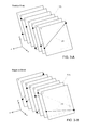
- FIGS. 3A and 3B are the a topological representation of an interconnection braid as a multi-layer structure, in which each strand is in a different layer and ordered according to a positive ( 3 A) or negative ( 3 B) ordering convention;
- FIG. 4A illustrates a perspective view of the interconnect volume showing an example trajectory to reconfigure a strand without entanglement and FIGS. 4B and 4C illustrate alternative braid ordering conventions for circuits within column i;
- FIGS. 5A and 5B are diagrams of the geometrical reconfiguration path of an individual strand with respect to a two-dimensional input matrix when constituent strands are ( 5 A) positively braided or ( 5 B) negatively braided;
- FIG. 6 illustrates an example of a multiplicity of independent interconnection braids comprising the switching system, with adjacent braids being opposite in sign to one another;
- FIG. 7 illustrates an example of a reconfiguration trajectory of the strand proximal end to move an interconnect from port A to port B for a system with adjacent subbraids having alternating signs;
- FIG. 8 is a diagram of the motion sequence to move the proximal end of fiber strand to increasing column number (moving right) for a positively braided column;
- FIG. 9 is a diagram of the motion sequence to move the proximal end of fiber strand to increasing column number (moving right) for a negatively braided column;
- FIG. 10 is a diagram of the motion sequence to move the proximal end of fiber strand to decreasing column number (moving left) for a positively braided column;
- FIG. 11 is a diagram of the motion sequence to move the proximal end of fiber strand to decreasing column number (moving left) for a negatively braided column;
- FIG. 12A illustrates a back perspective view and FIG. 12B illustrates a sagital view, partly in section, of the modular optical cross-connect system;
- FIGS. 13A and 13B illustrate partial front and perspective views respectively of a portion of a front connector row engagement ( 13 A) and a fragment of a row shifting actuation mechanism for a block of four input rows in a module comprising four reels;
- FIG. 14 is a fragmentary perspective view of the internal fiber optic connector which facilitates robotic actuation, machine-vision recognition, and two state engagement of individual cable elements;
- FIG. 15A is a fragmentary perspective view a connector gripper with integral camera system and FIG. 15B is a sagital broken away sectional view of the same showing further details;
- FIG. 16A is a top perspective view of a multiple level take-up reel module with four levels of twelve reels at each level and FIG. 16B is a plan view of one level of same;
- FIG. 17A is a fragmentary perspective of a portion of an interconnect transport mechanism
- FIG. 17B is a simplified side view showing the relationship between a transport mechanism and a matrix of terminals
- FIG. 17C is a simplified diagrammatic view of an alternative transport mechanism
- FIGS. 18A-18D depict, in fragmentary, broken away perspectives, different views of an individual take-up spool or reel for tensioning fiber strands of variable lengths and monitoring performance by an integral reel encoder;
- FIGS. 19A-19C depict in cross-section various examples of combinations of optical fiber and spring elements, interior to a portion of a take-up spool, in cross section;
- FIG. 20 is a block diagram of the architecture of a subsystem providing the capability to self-restore the cross-connect's operational state
- FIG. 21 illustrates an example of an array of shiftable input connectors, arranged in stacked rows on the wall of a housing, each row associated with a substantially parallel, flexible support suspended between fixed, rigid endpoints;
- FIG. 22 is a fragmentary enlarged perspective view showing fiber optic interconnections to each end of separate shiftable terminals in the array of FIG. 21 ;
- FIG. 23 illustrates a cross-section of a suspended, elastic cable management structure
- FIG. 24 illustrates in solid and dotted line representations, the change in configuration of a multiplicity of supported cables reconfiguring dynamically when connector receptacles shift parallel to elastic member.
- the all-fiber cross-connect switching system disclosed in this invention is illustrated in the partial cutaway, perspective view of FIG. 1 .
- This system is characterized by 100's to 1000's of flexible fiber interconnection lines or strands 21 suspended between two planes and intermixing within a circuit expansion volume 108 in the system interior.
- the placement, ordering and subsequent physical reconfiguration of strands is based on relationships derived from the Theory of Knots and Braids. Topological algorithms uniquely describe the dynamic nature of strand boundary conditions during the reconfiguration process.
- Reconfigurable fiber connections are made internal to the expansion volume 108 , between a two-dimensional array of reconfigurable input terminals 170 and an intermediate, substantially one-dimensional array or convergence backbone 41 bounding the interconnect volume.
- the suspended fiber lines 21 therebetween follow substantially straight-line paths and define a three-dimensional arrangement of vectors directed towards the one-dimensional array 41 which is located at an intermediate plane, beyond which the fiber lines 21 exit contiguously to a modular arrangement of substantially identical, stacked buffer modules 40 housing of a group of say, 48 strands.
- strand buffer or length storage elements 42 provide slight tensioning, parallel to the vectors and adequate to maintain taut fiber lines 21 in addition to retaining excess slack in the fiber lines.
- the tension force produced by storage elements 42 on each fiber line lies substantially parallel to the vector defining the three dimensional orientation of each fiber line.
- a typical optical cross-connect system in accordance with this example occupies a 19 or 23-inch wide rack and in this example contains up to 1008 input by 1008 output ports, or more.
- Switch terminals in array 170 can be added in fixed increments ranging from 12 to 48, for example, by installing additional flexible circuit modules 40 above any previously installed modules in the flexible fiber circuit expansion volume.
- the output fibers from the buffer modules 40 may be spliced to one or more multi-fiber cables 123 , or terminated directly at an array of connector terminals.
- the lower section of the switch volume is substantially comprised of the reconfiguration volume 108 .
- the reconfiguration volume 108 may lie at the top, bottom, side or central section of the system 100 .
- a central portion of the upper section is clear of obstructions to enable the robotic actuator to move, extend and park within this section while being unencumbered by the suspended fibers below.
- the bottom-most section (see FIG. 12B ) beneath the input terminal array 170 includes at least one row of translatable docking ports or parking ports in a docking module ( 215 in FIG. 12B ) to facilitate exchange of fiber lines 21 between and under the populated terminals.
- the polished fiber end-face of a connector can be cleaned prior to insertion at terminal array 170 by use of an integrated fiber end-face cleaning module (not shown in FIG. 1 ) which may be integrated within the interconnect transport mechanism 405 .
- the cleaning module may comprise a fiber cleaning fabric ribbon in spooled form and a drive mechanism which automatically moves the fabric relative to the end-face, thereby cleaning the fiber end-faces in a non-wearing fashion.
- This cross-connect system 100 is comprised of a combination of interchangeable modules to provide desirable characteristics of modularity, scalability and versatility ( FIGS. 12A and 12B ).
- the modules include a multiplicity of stacked flexible fiber optic circuit modules 40 populating an input connector array 110 , a robotic module 202 coupled to the interconnection transport mechanism 405 a controller module 70 , a docking module 215 , vertical cable guides 216 and output patch-panels 217 .
- the row-translatable, input terminal portion of the flexible circuit modules 40 are detailed in FIGS. 13A and 13B and are comprised of stacked rows 71 of connector terminals 58 for terminating fiber strands 21 (not shown here for clarity) and individually shiftable by means of a removable row shuffle actuator 64 subassembly.
- the excess lengths of fiber strands 21 are retained on take-up spools in the buffer modules 40 as is described in more detail below.
- unique barcodes 32 FIG. 13A
- the fiber interconnect module 40 further includes optical position sensors on a printed circuit board 39 ( FIG. 13B ) to unambiguously and independently reference the position of each row 71 ( FIG. 13B ) of terminals 58 ( FIG. 13A ).
- a multi-functional gripper 50 ( FIGS. 1 , 15 A and 15 B) is transported by the interconnection transport mechanism 405 to carry a strand or fiber line 21 to a different input terminal receptacle 58 in terminal array 170 ( FIG. 1 ).
- Any of the fiber circuits 21 are thus arbitrarily reconfigurable by engaging a selected circuit by this programmably moveable gripper 50 , which can reposition the connectorized fiber optic circuits 21 moving within interstitial regions adjacent the interior surface of the array of switch terminals 170 ( FIGS. 1 and 2 ).
- Non-interfering reconfiguration is accomplished by following a non-blocking path computed by the controller 70 ( FIG. 1 ) and based on knowledge of the vectors and configuration of all intermediate lines 21 ( FIG.
- the gripper includes a spring clip 66 ( FIG. 15A ) element to retain any connector 34 and seat this connector within support guide 67 during transport.
- the gripper 50 also includes image sensors 82 - 1 and 82 - 2 with imaging lenses 83 - 1 and 83 - 2 and integral LED light source 69 for use in vision alignment and barcode recognition.
- Rigid gripper extensions 68 are used to depress a latch retaining connector 34 within terminal 58 .
- the connector 34 includes a multi-segment clip body 35 with a miniature, unique barcode 32 attached to top surface for unambiguous identification of all fiber strands 21 .
- the clip body 35 includes two spaced apart notches 36 provided to separate latching positions during engagement of the connector 34 into terminal 58 ( FIG. 13A ).
- This gripper 50 thus may provide for machine vision alignment and inspection, electrical monitoring and power monitoring.
- the gripper is attached to the end of the y-axis linear actuator 65 ( FIG. 17A ).
- the integral cameras 82 FIG. 15B ) capture and relay video data to processor 70 , this data being used to direct the interconnection transport mechanism 405 during active alignment of gripper relative to a terminal of input array, or when reading absolute fiducial marks such as two-dimensional DataMatrix barcodes 32 adjacent each internal switch terminal 170 or two dimensional barcodes 32 ( FIG. 14 ) on connector 34 .
- this video data is processed in real time by pattern matching algorithms residing in the controller module 70 ( FIG. 12B ).
- Pattern or geometric matching algorithms are used to determine the physical center of each connector terminal 34 located on the interior side of the front panel terminal array 170 .
- the gripper is aligned in x, y, z directions with a selected fiber strand connector 34 utilizing closed-loop feedback to the motors driving the x-axis actuator 63 , y-axis actuator 65 and z-axis actuator 54 ( FIG. 17A ).
- Gripper 50 can utilize a semi-rigid, stiff spring element 66 ( FIG. 15A ) to clip or engage a connector 34 .
- a semi-rigid, stiff spring element 66 FIG. 15A
- the gripper is potentially connected to electrical ground, for example, so that when a fiber circuit is attached to the gripper, an electrical path can be established through multiplexed electronic sensing circuitry. A change in voltage across the electrical path then indicates whether the connector is properly seated and held within gripper 50 .
- the connector body is held within a die-cast metal clip 35 , the clip including retaining features or grooves 36 so that a spring element engaging these grooves can rigidly hold the connector 34 onto a mating terminal.
- the clip or connector body may include a miniature barcode 32 attached thereon that is identified by a miniature camera 82 ( FIG. 15B ) during the disengagement (or engagement) process. Barcode reading and pattern matching algorithms are utilized to confirm proper clasping and unclasping of the connector 34 with gripper 50 .
- the gripper 50 is attached to one end of the y-axis linear actuator 65 ( FIG. 17A ), which is, for example, a stiffened linear shaft fabricated of aluminum, stainless steel or carbon fiber composite.
- the linear actuator may consist of a series of extendable, telescopic tubes to reduce the overall height of the system when the gripper is withdrawn from the interconnect volume.
- FIGS. 17B and 17C illustrate a second robotic approach to positioning based on a gantry that lowers a shuttle 56 or fiber transporter with translatable gripper 62 attached via support cables 61 down the column track 57 onto a particular circuit connector 58 to be reconfigured.
- the use of cable actuation through the support cables enables the length of the monolithic, rigid y-axis actuator 65 to be reduced relative to FIG. 17A , because the shaft length of y-actuator does not need to rise above the interconnect volume 108 (seen in FIG. 12B ) before, during and after reconfigurations.
- the actuator cables 61 are retained on motorized reels 60 that raise and lower the shuttle 56 , as well as translating the gripper along the z axis to engage or disengage the circuit attached to the front adapter connector.
- the y axis actuator can utilize telescopic tubes, or other mechanical approaches developed for extendable booms, to reduce the vertical clearance needed when the y-actuator 65 ( FIG. 17A ) is fully withdrawn above the interconnect volume.
- Each row of connectors 71 on the lower input array illustrated in FIGS. 1 and 14B can independently shift laterally on actuation by row shifters 33 shown symbolically in FIG. 17B and described in FIGS. 1 and 12B in the previously referenced parent applications under the command of controller 70 .
- Row shifting enables the implementation of unique reconfiguration algorithms based on coordinated motion of the gripper 50 and the row translations to “weave” a non-repeating braid arrangement of fiber strands.
- Reconfiguration is initiated by a user or external software client by entering a simple reconfiguration command, reading in a file containing a series of reconfiguration instructions, or via a standard interface protocol such as TL1 or SNMP (Simple Network Management Protocol).
- the server or controller system 70 processes these commands, based on the current state of the database of interconnection vectors, to compute the required multi-step, Braid theory-based reconfiguration process. Thereafter, the motion of interconnection transport mechanism 405 is initiated.
- the multifunctional gripper 50 disengages and moves a specified fiber line, in a fashion synchronized with the programmed, independent translation of each row comprising the two dimensional array of terminals 170 along the x axis. Fiber lines retain substantially straight-line paths for any number of arbitrary reconfigurations.
- the vector undergoing reconfiguration maintains a proper orientation relative to surrounding vectors such that entanglement is avoided for any potential reconfiguration.
- input terminals are connected to output fibers through internal connections that are robotically reconfigured.
- a reconfiguration of one port first requires that if the internal destination port 58 is currently occupied by a connector 34 , this connector must be vacated to make room for the new fiber connection. This process makes temporary use of a holding, docking or parking port, for example, within docking module 215 below the flexible circuit modules 40 ( FIG. 12B ). If the destination port is not vacant, the port reconfiguration is preceded by the step of moving any fiber strand 21 within the destination port to an empty terminal 58 ( FIG. 17B ). In general, the number of internal input terminals 58 will be larger than the number of output fibers 81 ( FIG. 1 ) because of the addition of docking and/or parking ports.
- the figures referenced herein depict cross-connect systems in which the columns (y direction) are vertical and the rows (x direction) are horizontal.
- columns and rows can be oriented either vertically or horizontally, depending on the size and form factor requirements of the particular application. For example, for height-constrained applications, they axis may be oriented horizontally.
- the optimal reconfiguration process in terms of speed does not necessarily reconfigure one port at a time in the order dictated by a batch process file. Instead, the entire set of reconfigurations should be processed such that an optimal sequence of reconfigurations is performed based on a least path optimization process. This process analyzes the current configuration and the availability of vacant nearest neighbor ports to determinate the most efficient reconfiguration scenario (i.e., fastest).
- the port configuration file resides within the memory of controller 70 .
- the system receives an instruction in which a first strand currently attached to a first input terminal 58 is to be connected to a second input terminal.
- the reconfiguration file in memory is read to determine if the second input terminal must be first vacated. If so, the second strand corresponding to the second input terminal is moved to the nearest empty port. Once the second input terminal is empty, the first strand can be moved to this terminal to establish the new link. The second strand remains available for future operations.
- the spatially coherent set of strands or links is represented by the group of positive and/or negative non-repeating braids.
- the signs of the braids are dictated by a given ordering convention that is maintained during all reconfigurations during the lifetime of the system. For example, all subbraids within the interconnect volume may be positive, negative, or some combination thereof.
- Arbitrary reconfigurations are achieved, referring now to FIG. 1 , by translating the origin of the vector associated with a fiber line 21 through the region of interconnect volume 108 immediately adjacent to the two dimensional array of terminals 170 (seen in FIG. 2 ). This moving vector weaves through the surrounding space of vectors in a non-interfering, column-by-column fashion. Translation across, up and down columns 101 is directed by electronic positioning controls generated by controller 70 to activate the interconnection transport mechanism 405 .
- Reconfigurations of flexible, yet taut, fiber lines 21 are made internal to the interconnect volume 108 by disengaging, translating and re-engaging fiber line 21 connectors 34 adjacent the internal surface of the two-dimensional input array 170 of internal terminals 58 under the control of the interconnection transport mechanism 405 , movable along three orthogonal axes to maneuver around surrounding suspended fibers 21 .
- the interconnect volume 108 is bounded on the input side by the array of terminals 170 and on the opposite side by a substantially one-dimensional array of fiber through-ports or guides in substantially linear alignment along a fiber backbone 41 lying at an intermediate plane within the cross-connect system.
- Each strand 21 passes through a unique and fixed guide at a different point midway along the strand length.
- the fiber strand interconnection volume 108 thus lies between two planes spaced apart by a distance L.
- the first plane coincides with the input terminal array 170 and the second plane coincides with the convergence backbone 41 .
- the internal connections made to the input terminal array are reconfigurable. While not depicted graphically in FIG. 2 , strands 21 terminate in reconfigurable connectors 34 that mechanically and optically latch to mating connector receptacles 58 at input connector array 170 , as shown and described in greater detail in the referenced, previously filed parent applications.
- Reconfiguration algorithms are calculated based on a state representation of the spatial relationships between an intermixed yet spatially coherent arrangement of physical interconnects.
- the group of fiber strand interconnections is mathematically represented by a Braid Group, with an associated algebra necessary to represent the various geometrical relationships and operations on the interconnect strands comprising the braid.
- Each fiber interconnect 21 suspended between the input plane 91 and intermediate plane 93 is mathematically equivalent to a strand or vector joining two points in opposite planes.
- the geometric relationships and boundary conditions of strands change arbitrarily as a result of reconfiguration. To avoid physical knotting or tangling of these strands, which prevents subsequent reconfiguration, the crossing characteristics in relation to other strands must be determined.
- One end of a particular strand at the input plane is maneuvered at its endpoint (the physical embodiment of its boundary condition) such that the strand passes through the interconnect volume without entangling other strands.
- a fiber optic connection at the front input terminal array 170 is reconfigured by physically translating its proximal endpoint 22 within the interstitial gaps 118 between the arrayed interconnections terminating at input terminals 58 .
- endpoint 22 remains close to the plane of the input array, travelling within interstitial gaps 118 between strands to allow physical access for the gripper 50 .
- the interconnects' distal endpoints 23 extend through the intermediate array 41 to the output fiber assembly 81 ( FIG. 1 ) and the configuration of endpoints 23 remains fixed.
- the multiplicity of strands can realize an infinite number of configurations. Knotting of strands is possible if the interconnect paths 21 are spatially indeterminate and if the length of the strand is greater than a straight-line path. Instead, least-path, variable length interconnects are provided by retaining excess fiber lengths outside the strand mixing volume to prevent knotting. Fiber tensioning and storage modules 40 are disposed opposite the intermediate plane 41 and adjacent to the strand volume 108 . In this manner, strands 21 follow substantially straight-line paths, defining vectors connecting the input 170 and intermediate 41 arrays.
- Geometrical “order” of strands within the interconnect volume is achieved by interconnecting the 2-D input array of strand terminals to a 1-D intermediate array of strand guides.
- the interconnect strands between a 4 ⁇ 4 input terminal array 170 and a 16 ⁇ 1 port intermediate port array 41 is shown in FIGS. 2A and 2B .
- the strands 21 follow straight-line paths between the input plane 91 and intermediate plane 93 .
- the mapping of the 2-D inputs to a 1-D array performs the mathematical equivalent of “combing” the interconnection braid, to form independent, spaced-apart subbraids.
- the interconnection geometry retains a deterministic arrangement, despite the potentially arbitrary state of interconnections.
- the entire interconnection braid is subdivided into separate, independent subbraids or zones 101 - 1 , 101 - 2 , 101 - 3 , 101 - 4 originating from each column of input terminals. That is, reduces to the subbraid group wherein a is the number of TOWS.
- each subbraid is non-repeating; that is, any two of its strands cross at most once. Strands do not span more than one zone in any final interconnect configuration. This configuration ensures the strands remain disentangled.
- the strands 21 of the non-repeating braid are overlaid back to front without intertwining. From a topological perspective, strands lie within separate layers, eliminating the proclivity to tangle.
- Each strand is topologically equivalent to a “page” in a book, where pages are ordered in an ascending (i.e. positive) or descending (i.e. negative) sense, and each subbraid is a “chapter” of the book.
- the set of all N switch interconnections forming the spatially coherent switch state, with a particular set of boundary conditions, is represented by an N-stranded braid. Practically, the interconnections must remain knot-free. Mathematically, this means the interconnections correspond to braids comprised of strands with
- ⁇ 1, which are conventionally called positive (x>0) ( FIG. 3A ) or negative (x ⁇ 0) ( FIG. 3B ) non-repeating braids. Positive denotes that the braid only has positive crossings, that is, the front strands have a positive slope. Each strand 21 can be thought of as residing in its own layer 175 , which can be individually peeled away from other layers.
- the collection of strands 21 comprising the non-repeating braid are represented as a sequentially ordered series of layers 175 , wherein layer identifiers “1”, “2”, “3”, “6”, “8”, “10”, and “13” denote the elevation of strands at the 1-D backbone 41 .
- the layers are arranged in ascending order with spatial coordinate x, defining a positive braid.
- the layers are arranged in descending order with x, defining a negative braid. Due to its non-repeating, layered braid structure, layers are independent and individual layers can be moved or removed from the braid without entanglement.
- the reconfiguration of a circuit passes from subbraid i ⁇ 1 to subbraid i+1 by traversing an intervening subbraid i ( 101 -i) in a manner that avoids knotting of circuit 21 ′ ( FIG. 4A ).
- the circuit 21 ′ undergoing reconfiguration is initially attached to terminal A within subbraid i ⁇ 1, and is moved to terminal B within subbraid i+1 of input array 170 in a non-blocking fashion.
- the strand successfully passes from column i ⁇ 1 to column i+1 by traversing an intermediate column i in a manner that avoids entanglement. If the strand were reconfigured by moving the proximal end of strand i from a terminal A to a terminal B along a direct straight-line path in the plane parallel to input array, the strand 21 ′ would become physically entangled with other strands of subbraid i. Entanglement prevents subsequent reconfiguration through the knotted region and leads to imminent failure of the switching system.
- a proper path 111 of the strand endpoint 22 is represented by the dotted line in FIG. 4A , wherein the strand passes below those strands originating from a higher level at the switch backbone and above those strands originating from a lower level at the switch backbone.
- FIGS. 4B and 4C illustrate topologically equivalent end-on views of strands within the zone i.
- the circuit j passes between these separate layers corresponding to strands “8” and “10”.
- the subbraid essentially separates into two partial subbraids with a gap formed therebetween. Consequently, path 111 does not cross nor entangle adjacent strands.
- FIGS. 4B and 4C illustrate two alternative implementations of the ordering rule, corresponding to positive and negative braids, respectively. These figures are non-physical and provide a topological view of a particular zone 101 -i by revealing the ordering of layered circuits 21 therein.
- a positive braid ordering rule requires that fiber circuits 21 be placed from left to right within each zone 101 with increasing addresses (or elevations) at the one dimensional backbone.
- the addresses are in general non-sequential and in this particular example for illustration purposes, are labeled “1”, “2”, “3”, “6”, “8”, “10”, “13”, and “14”.
- a negative braid ordering rule requires that fiber circuits 21 be placed from left to right within each zone 101 with decreasing addresses (or elevations) at the one dimensional backbone. Note that the trajectories to reconfigure circuits for these two conventions are different. Non-entangling algorithms can be developed regardless of the sign of the braid, as long as it is either positive or negative non-repeating.
- FIG. 5A illustrates an example terminal-map 110 and reconfiguration trajectory to move the proximal end 22 of a strand 21 from a terminal A to a terminal B within the array of input terminals 170 , in which the interconnections are ordered according to a positive braid.
- This terminal map 110 depicts a 10-column by 14-row array of terminals, wherein the numbers associated with each terminal correspond to the address of the particular circuit 21 attached thereto.
- Each fiber circuit 21 within the column originates from a different level of backbone 41 and is associated with an address used to determine the proper non-blocking trajectory for the circuit. In these examples, for illustration purposes, each terminal has been assigned a fiber circuit with a random address.
- a second circuit presently at port B is moved to a docking port (not shown) to vacate port B.
- FIG. 5A for a positive braid and FIG. 5B for a negative braid as the first circuit moves from left to right across this array of ports, it passes through intervening columns or subbraids 101 - 1 , . . . in a sequential fashion, without entangling any potentially crisscrossing circuits within the columns.
- the particular circuit A follows a path crossing above or below the columns of connectors and their attached fibers, wherein fiber circuit A passes below those optical circuit elements which originate from higher levels at the backbone and pass above those elements which originate from lower levels of the backbone.
- the paths represented by FIGS. 5A and 5B represent the relative positions of the various circuits and are not to scale, nor are they representative of the true physical path. The actual trajectory is dependent on the chosen actuation approach.
- Consistent ordering rules enable the multiplicity of strands to maintain a coherent, ordered state reconfigurable for an unlimited number of times, without compromising coherence and the non-repeating braid structure. Order is reflected in the assignment of a consistent positive or negative braid ordering convention to each successive column of the input terminal array.
- FIG. 5A and FIG. 5B present reconfiguration paths consistent with the rules delineated in the previously filed parent applications as to the braid orientation of each column.
- the positive direction is defined as the direction of increasing column number (x direction in figures).
- Shuffling of a particular braid or column consists of the lateral shifting of each row 71 by half the intercolumn spacing in the direction of increasing column number, wherein the direction of shuffling for that particular braid or column depends on the one-dimensional backbone 41 address of the strand 21 undergoing reconfiguration and the backbone addresses of each strand within the particular braid or column 101 .
- a row shifts to increasing column direction if the particular strand within that row of the particular column has a backbone address greater than the backbone address of the strand undergoing reconfiguration.
- a row shifts to decreasing column direction if the particular strand within that row of the same particular column has a backbone address less than the backbone address of the strand undergoing reconfiguration.
- a row shifts to decreasing column direction if the particular strand within that row of the particular column has a backbone address greater than the backbone address of the strand undergoing reconfiguration.
- a row shifts to increasing column direction if the particular strand within that row of the same particular column has a backbone address less than the backbone address of the strand undergoing reconfiguration.
- the positive braid when the strand undergoing reconfiguration changes row position while remaining within the same positive braid, the positive braid must undergo a positive shuffle and the strand undergoing reconfiguration may weave up or down the braid.
- the negative braid when the strand undergoing reconfiguration changes row position while remaining within the same negative braid, the negative braid must undergo a negative shuffle and the strand undergoing reconfiguration may weave up or down the braid.
- a programmable cross-connect comprises a multiplicity of rows 71 of input terminals in dynamic alignment to one another. Independent actuation and translation of entire connector rows 71 along the x direction is provided by a programmable shuffling mechanism 64 .
- the paths shown in FIG. 5 are implemented by both gripper 50 motion and transverse actuation of each connector row 71 .
- the gripper 50 translates up and down columns in a straight-line path, with the rows 71 shuffling transversely according to the shuffle pattern to ensure that the particular fiber circuit 21 moves to the left or right of other circuits within the column.
- the circuit moves according to a sequence of steps comprised of alternately descending into and ascending out of the intercolumn gaps 118 .
- the circuit must fully clear the first subbraid 101 - 1 before entering and weaving through the second subbraid 101 - 2 .
- each subbraid comprising the interconnect system such that it alternates for adjacent subbraids.
- each subbraid is an independent “chapter”, and the “pages” of even numbered “chapters” have an ascending (positive) order and the “pages” of odd numbered “chapters” have a descending (negative) order.
- FIG. 6 which schematically depicts the topological distribution of negative braids 176 - 1 and positive braids 176 - 2 , and FIG. 7 , the sequential trajectory of a strand is illustrated as it is repositioned from an initial address A to a target address B with this alternating sign topology.
- FIG. 6 schematically represents this alternating-sign braid topology, with magnified views of the individual ordered layers comprising the adjacent positive and negative braids.
- This configuration offers the advantage of most efficient and rapid reconfiguration, the result of it minimizing the cumulative travel distance of the gripper during the reconfiguration process.
- the first column 1 (to the left) is a negative braid, and the sign of the columns alternate thereafter.
- FIG. 5A all positive braids
- FIG. 5B all negative braids
- the length of the equivalent reconfiguration path and the reconfiguration time is reduced by about a factor of two by alternating the sign of adjacent braids.
- the movable endpoint of circuit 21 ′ is translated by a sequence of steps illustrated in FIGS. 8 through 11 .
- FIGS. 8 through 11 These figures graphically represent sub-reconfiguration processes moving to the left and right in the input array, for positive and negative braids.
- the dashed lines represent the path of the fiber endpoint undergoing reconfiguration, and the solid lines represent the path of the gripper.
- the reconfiguration trajectory is in general composed of any of these twelve sub-processes.
- Sequence A represents the initial removal of a circuit from its originating terminal
- sequence B represents a circuit crossing an intermediate column
- sequence C represents the final insertion of a circuit into its destination terminal.
- the reconfiguration time may be reduced for instances where the backbone addresses of two or more adjacent columns are all above or below the backbone address of the circuit undergoing reconfiguration.
- the gripper may carry the circuit over columns in which the backbone addresses of the entire column lie below that of the circuit undergoing reconfiguration.
- the gripper may disengage the circuit from the docking port, allow the docking port to shift to the left or right, reengage the circuit into the docking port, and finally move the docking port to shift to the right or left, respectively.
- FIG. 8 illustrates reconfiguration sequences for a move to the right (positive move) at positive braid columns.
- sequence A corresponds to the removal of a circuit from its originating terminal 279 , followed by a move to the right at a positive braid.
- This sequence begins with a shuffle step 274 of the rows of the column in directions based on the numbered addresses of fibers 21 ′ at the convergence axis 41 .
- the gripper descends into the columnar gap formed during the shuffling process, physically splitting the subbraid into two partial subbraids, and disengages (step 271 ) the starting connector from a front panel receptacle.
- the connector attached to this circuit is disengaged from its initial port 279 .
- the gripper then moves to the bottom of this column through the split subbraid to engage the connector into a bottom docking port 280 . After engaging the circuit into the docking port, the gripper returns to the top of the column. The docking port moves to the right, carrying the circuit 21 ′ therewith. The gripper then shifts (step 273 ) by a column spacing to the right to begin the next move, which, in the preferred example of the alternating sign braid configuration, would correspond to a negatively braided column.
- sequence B corresponds to the crossing to the right through an intermediate positive braid.
- the sequence begins with row shuffling (step 274 ) determined by a calculation based on the address of the circuit undergoing reconfiguration and the addresses of all circuits within the intermediate braid to generate the shuffle pattern or bipolar shuffle code.
- the gripper descends down the column, carrying the circuit, and engages the circuit at the bottom most docking port 280 .
- the gripper then returns to the top of this column and the gripper shifts (in step 273 ) to the right by a column spacing to the top of the adjacent column.
- the docking port also shifts (step 276 ) by a column spacing to the right, carrying the circuit under and across the braid to new position 281 .
- sequence C illustrates the insertion of the circuit into its destination column, for a move to the right at a positive braid.
- the rows shuffle (step 274 ) and the gripper carries the circuit down the center of the column and engages (step 272 ) the circuit in the destination port 281 .
- FIG. 9 illustrates the sequences for a move to the right (positive move) at a negatively braided column.
- sequence A corresponds to the removal of a circuit from its originating terminal 279 , followed by a move to the right at a negative braid column.
- Sequence A begins with a shuffle (step 274 ) of the rows of the column in directions based on the numbered addresses of fibers 21 ′ at the convergence axis 41 to provide a bipolar shuffle pattern, that is, one moving by a fixed increment in one of two opposite directions.
- the gripper descends into the columnar zone opened during the shuffling process, physically splitting the subbraid into two, and disengages the starting connector from its front panel receptacle 279 .
- the connector attached to this circuit is disengaged at step 271 from the initial port 279 .
- the gripper then returns to the top of this column through the split subbraid.
- the gripper shifts laterally in step 273 by a column spacing to the right to begin the next move, which, due to the alternating sign braid configuration, would correspond to a positively braided column.
- sequence B corresponds to the crossing to the right through an intermediate negative braid.
- the sequence begins with a row shuffle (step 274 ) determined by a calculation based on the address of the circuit undergoing reconfiguration and the addresses of all circuits within the intermediate braid, which is used to determine the braid code or pattern of equi-distance shifts.
- the gripper descends down the column and disengages at step 271 the circuit from the bottom most docking port 279 .
- the gripper then returns to the top of this column carrying the circuit, and the gripper then shifts (step 273 ) to the right by a column spacing to the top of the adjacent column.
- sequence C illustrates the insertion of the circuit into its destination column, for a move to the right at a negative braid.
- the gripper carries the circuit upward until it reaches the destination row, and inserts (step 272 ) the circuit into the destination port 281 .
- FIG. 10 illustrates the reconfiguration sequences for a move to the left (negative move) at columns ordered as a positive braid.
- sequence A corresponds to the shuffle (step 274 ) of rows, the disengagement (step 271 ) of a circuit from its originating terminal 279 , followed by a shift (step 273 ) to the left at a positive braid.
- Sequence A begins with the shuffling of rows of the column in directions based on the numbered addresses of fibers 21 ′ at the convergence axis 41 .
- the gripper descends into the columnar zone opened during the shuffling process, effectively splitting the subbraid into two.
- the connector attached to this circuit is disengaged (step 271 ) from its initial port 279 .
- the gripper then moves to the top of this column through the split subbraid.
- the gripper shifts (step 273 ) by a column spacing to the left, which, due to the alternating sign braid configuration, would correspond to a negatively braided column.
- sequence B corresponds to the crossing to the left through an intermediate positive braid.
- the sequence begins with row shuffling (step 274 ) determined by a calculation based on the address of the circuit undergoing reconfiguration and the addresses of all circuits within the intermediate braid.
- the gripper descends down the column and disengages (step 271 ) the circuit from the bottom most docking port 279 .
- the gripper then returns to the top of this column with the circuit and the gripper shifts (step 273 ) to the left by a column spacing to the top of the adjacent column.
- sequence C illustrates the insertion of the circuit into its destination column, for a move to the left at a positive braid.
- the docking port with the circuit shifts to the left, the rows shuffle (step 274 ) and the gripper descends down the center of the column to disengage (step 271 ) the circuit from the docking port 279 .
- the gripper rises to the destination row and engages (step 272 ) the circuit into the destination port 281 .
- FIG. 11 illustrates reconfiguration sequences for a move to the left at a negative braid column.
- sequence A corresponds to the removal of a circuit from its originating terminal, followed by a move to the left at a negative braid column.
- Sequence A begins with shuffling (step 274 ) the rows of the column in directions based on the numbered addresses of fibers 21 ′ at the convergence axis 41 .
- the gripper descends into the columnar zone opened during the shuffling process, effectively splitting the subbraid into two, and disengages (step 271 ) the starting connector from its originating port 279 .
- the gripper carries the circuit down to the docking port, and engages (step 272 ) the connector into the docking port 280 .
- the gripper returns to the top of the column through the split subbraid.
- the gripper then shifts (step 273 ) by a column spacing to the left to begin the next move, which, due to the alternating sign braid configuration, corresponds to a positively braided column.
- the docking port shifts (step 275 ) to the left to carry the circuit to the bottom of the adjacent column.
- sequence B corresponds to the crossing to the left through an intermediate negative braid.
- the sequence begins with row shuffling (step 274 ) determined by a calculation based on the address of the circuit undergoing reconfiguration and the addresses of all circuits within the intermediate braid.
- the gripper carries the circuit down the column and engages (step 272 ) the circuit into the bottom most docking port 280 .
- the gripper then returns to the top of this column, and the gripper then shifts (step 273 ) to the left by a column spacing to the top of the adjacent column.
- the docking port shifts (step 275 ) to the left, carrying the circuit to the bottom of the adjacent column 281 .
- sequence C illustrates the insertion of the circuit into its destination column, for a move to the left at a negative braid.
- the modular construction is shown in FIGS. 16A and 16B and comprises a number (four) of stacked take-up reels 42 , each in a separate partial housing of low height (0.4 inches or less), and each, in this example, comprising one reel 42 in a four high stack of reels distributed in a 4 ⁇ 3 planar configuration, as shown in FIG. 16B .
- the optical fibers helically wrapped around the reels 42 and extending from the inner, or rotatable hub, of each of the individual reels 42 are fed into a fiber backbone 41 ( FIG. 16A ) as described above and in the previously referenced parent applications and from there are distributed outwardly into an open interconnect volume 108 leading to individual connector terminals 110 .
- Each module includes a rigid printed circuit board substrate 84 on which forty-eight take-up reels 42 reside, each feeding their fiber 21 to a different connector terminal 110 , the terminals 110 being accessible from the exterior.
- Fibers 21 are individually routed from the rotatable outer walls of reels 42 through a series of low friction fiber guides 92 that suspend the fibers passing therethrough and direct them potentially through 90 degree bends, while presenting negligible friction to the fibers sliding within.
- the fiber guides 92 are positioned across the printed circuit board substrate 84 to route all moving input fibers to the central fiber backbone location 41 .
- the connector terminals 110 connect outwardly to exterior optical fibers in the system harness.
- this compact module is of less than 1.6 inches height, so that a significant number of modules can be added as needed and stacked within the equipment rack.
- FIG. 20 Data and procedures used in the execution of a deterministic, multi-state port reconfiguration process is recorded in real-time during the process to provide a detailed log file 209 record of the steps being effected. Should a power failure or other fault or failure occur to interrupt the reconfiguration process, the saved log file is restored to reveal the exact point in the reconfiguration process where the fault occurred. For robustness, the log file is typically saved to a mirrored or redundant memory device at the same time.
- the reconfiguration is restarted in a simulation mode following interruption. That is, the controller steps through the reconfiguration process without executing the actual processes, such as actuation of the gripper.
- the saved log file is compared to the simulation log file line-by-line during process simulation, which should match on a line-by-line basis until the point of failure.
- the simulation process reaches the final entry in the saved log file, the process has returned to the point at which it had halted. At this point, the process exits the simulation mode and proceeds with the execution of the actual process.
- the recording of all steps within the reconfiguration process is augmented by a variety of recorded sensing signals, derived from a distributed sensor subsystem 208 , including rotary encoders and photosensors, for example, a camera-based pattern recognition subsystem 207 , a camera-based barcode recognition subsystem 218 , and a take-up reel encoder subsystem 219 .
- the log file serves as the equivalent of an internal “black-box recorder” which records the state of the system and conditions leading up to a service interruption or failure. This feature enables the cross-connect system 100 to restore itself to a mode of proper operation even after an interruption in the reconfiguration process due to an earthquake or power outage, for example. This restoration process is desirable because the stability of reconfiguration algorithms and the preservation of coherent ordering depend critically not only on the initial and final states, but also on the exact strand trajectory followed during intermediate states.
- the take-up reels as shown are angularly biased in a more central fashion and include a molded, circular, notched encoder wheel 45 that periodically interrupts the light path of a photointerrupter circuit 46 .
- the notched wheel interrupts the light beam, providing a rotatable circumferential indexer about the central axis, and the photointerrupter 46 thus produces a series of electronic pulses that are received and converted into a corresponding electrical (e.g., TTL) pulse train.
- TTL electrical
- the body of the reel 43 is configured such that it has an outer rotatable wall above which the turns of optical fiber 21 are wrapped, with the opposite ends extending respectively to the input and output of the reel 43 .
- the view of a half section of the reel ( FIG. 18C ) is submitted to show this most clearly, in the helical path defined by the optical fiber in the reel. It also shows how the reel comprises an interior hub rotatable within the reel body, so that the external portion of the fiber can be shortened or lengthened as needed when changing the routing of a fiber.
- An electronic counter circuit counts these pulses and reports the total count back to the primary processor. The count is compared to an estimate based on geometrical calculations of the change in path length while moving across each column. The different between the measured and calculated counts must be less than a predetermined error value for proper operation.
- Reliability of flexible fiber circuits is improved by sleeving the coated optical fiber 24 with a semi-rigid, low friction PEEK plastic loose tube 49 ( FIG. 19A ).
- PEEK tubing with 0.030 to 0.040 inch outer diameter and 0.015 to 0.025 inch inner diameter is optimal to provide effective strain relief and the low friction characteristics to enable the movement of tensioned flexible circuits during the dynamic reconfiguration process.
- the spring tensioning force for the take-up reel is provided by a spring tempered steel wire 52 of 0.016 to 0.032 inch diameter that is longitudinally adjacent the optical fiber 24 .
- Unique electronic identification of the strand can be achieved through a tracer wire 51 , which is optional.
- the spring and optical fiber are maintained in parallel alignment within a flat, thin-walled plastic sleeve 48 or dual lumen tube 53 and forming a coiled element 67 .
- the material for the tube is typically a low friction material such as PEBAX, PTFE, PFE).
- the typical sleeve wall thickness is 0.0015 to 0.015 inch.
- the fiber-spring coiled element 67 is about 30 to 150 inches long and winds and/or unwinds as the reel 43 rotates.
- the spring wire 52 causes the reel to automatically wind any excess fiber lengths.
- the loose tube and thin-walled sleeve are replaced by a dual lumen tube 53 , fabricated of nylon, PEBAX or PVC, for example.
- This tube retains the spring 52 and fiber 24 in longitudinal alignment.
- the outer surface of the dual lumen tube can neck down at the mid-section ( FIG. 19B ) or have flat outer surfaces ( FIG. 19C ).
- the tubing may be coated with an additional material (i.e., PTFE) to reduce the coefficient of friction.
- the reconfiguration speed of the cross-connect switch is limited by the speed in which flexible fiber circuits are rewound onto the take-up spools.
- the robotic gripper 50 passes alongside each subbraid, the suspended length of fiber within the interconnection volume varies. The excess length is retained by the take-up spools 42 .
- the rotation speed of the take-up spools is dependent on the torque provided by the fiber-spring coiled element 67 , friction of the flexible fiber circuit and reel, and the mass of the reel and flexible fiber circuit. By reducing the mass and friction of the various elements, winding speed can be significantly reduced for high-speed operation. In general, there are limits to the tension of the fiber-spring coiled element 67 , to prevent excessive forces on the optical fiber components.
- the locations of the input connector receptacles are arranged in rows 71 , the rows remaining fixed in position during the lifetime of the panel.
- the automated patch-panel system disclosed herein is comprised of a stacked arrangement of independently translatable rows 71 with input connector receptacles, and programmed row translation is coordinated with the motion of the internal robotic gripper 50 .
- This configuration enables the gripper to travel at high velocity up and down columns 101 , without the need to stop or change direction as it works its way up or down the column.
- Each row of connectors 71 includes a low friction, internal linear slide mechanism with precise positional references to ensure that all rows of the connector can be aligned horizontally (forming aligned vertical columns).
- FIG. 13B illustrates a partial view of the translation mechanism, including actuation element 64 and position sensing circuit 39 .
- the switch is provided with a number of input ports greater than the number of output ports. This enables excess input ports to be used as parking locations for unused fibers. An unused fiber is moved to the nearest open parking locations, as needed to quickly vacate a port.
- an input port and output port or output fiber pair are specified.
- the input port may be already occupied by an output fiber, so that this output fiber must first be moved to a parking location.
- the time to perform this step is minimized by providing a number of parking locations, wherein the parking locations are advantageously in the vicinity of the input port to minimize the distance that must be traveled to prepare the input port for a new fiber. For example, in a system with M columns of connectors, there may be one or more open ports per column, for >M empty ports.
- parking locations are provided alongside one or more rows of the docking module 215 as shown in FIG. 12B .
- Prior art cable management techniques do not offer support for large numbers of fiber optical cables horizontally routed to automated cross-connects whose connector rows translate during reconfiguration.
- the high density of external fiber optic cables interfaced to the front connector array in accordance with the prior art arrangements susceptible to entanglement due to the sag of individual cables under the effects of gravity.
- the rigid nature of prior art support structures limit access to front panel connectors and compromise the ability to reconfigure patchcords.
- there is a need for cabling interconnect techniques that facilitate the horizontal routing of significant numbers of fiber optic cables in a simple and inexpensive fashion while simultaneously preserving accessibility to cables and connectors while not impeding incremental lateral translation.
- there is a need to effectively manage front-side patchcords on a row-by-row basis to facilitate automated lateral shuffling of connector terminal points within a fiber distribution rack, without introducing excessive stress on the fibers.
- fiber optic cables attached to an external facing, horizontal row of connector terminals comprising part of an equipment frame are supported in parallelism to and at some distance from the row of terminals to a suspended, tensioned elastic support structure ( FIGS. 21 , 22 and 24 ).
- the elastic support structure 75 includes cords with substantially circular cross-section and fabricated of natural or synthetic elastomers exhibiting extensions of typically 20% or more.
- fiber optic cable-to-support attachment methods include a metal or molded plastic clip or hook-and-loop type of strap (e.g., VelcroTM) 77 ( FIG. 23 ), for instance.
- the elastic suspension member 75 is rubber cord covered with nylon, polypropylene or polyethylene fabric, or synthetic elastomer such as polyurethane. Typical cord materials can be extended by at least 100% under tension.
- Elastic cord may be in the form of a fabric covered latex rubber cord (i.e., “bungee cord”), covered with woven fabric to prevent abrasion to the core even when stretched. Such rubber cord typically stretches up to twice its length.
- the cord may include the class of elastomeric materials including EPDM rubber cord, which is weather resistant and will stretch up to three times its length, and polyurethane cord, which withstands oils, ozone and salt water, stretches to two times its length and has good “memory” that prevents it from permanently stretching.
- EPDM rubber cord which is weather resistant and will stretch up to three times its length
- polyurethane cord which withstands oils, ozone and salt water, stretches to two times its length and has good “memory” that prevents it from permanently stretching.
- typical elastic cord diameters are 0.25 inch or less, more commonly in the range of 0.062 to 0.187 inch.
- small diameter cordage under tension is effective at vertically supporting and horizontally routing optical fiber to the edges of the equipment frame.
- the low transverse force produced by the tensioned cordage 75 ensures that a minimal shear stress is transferred to the optical fiber as the fiber cable 73 undergoes a 90-degree bend to achieve parallelism between fiber cable 73 and support cord.
- the cables 73 extending from the connectors in each row 71 can shift incrementally, as shown by the dotted line position in FIG. 24 .
- FIG. 23 illustrates in section a particular example of one of multiple flexible cable support cords 75 which are disposed in parallel with an equal number of fiber optic connector terminal rows 71 ( FIG. 21 ) comprising the connector interface to a particular fiber optic device.
- the fiber optic cables may be individually attached to suspended cords with small hook-and-loop straps 77 , typically 1 inch wide and chosen to have a length adequate to encircle the bundle of cables and suspension support member.
- the cord diameter is about 0.1 inch and the cord-to-cord interval is 0.5 to 1.5 inches, corresponding to the spacing of connector rows at the fiber optic device.
- the cords are tensioned by fixed, rigid supports 76 ( FIG. 21 ) at the cord 75 endpoints and in the vicinity of the edges of the equipment frame.
- adjacent cords can be easily separated as shown symbolically in FIG. 21 to displace cables in a non-invasive fashion and provide clearance for a technician's hand or tools to conveniently extract or insert a cable from or into the receptacle without affecting transmission in surrounding cables.
- this enables a high fiber density to maximize space utilization without limiting physical access to individual cables.
- FIG. 24 also illustrates the routing of pre-fixed fiber optic cables outwardly from a row 71 of terminals in the two-dimensional matrix to the left side of the connector panel.
- the fiber optic cables 73 generally must undergo a turn of up to 90 degrees to route along a path parallel to the row and extend to one or the other of the outermost edges of the equipment rack.
- the cables are attached to the support cord such that the quarter turn includes a small excess cable length (typically 0.5 to 1.5 inches) to ensure minimal shear forces.
- vertical cable management “ladders” 74 are used to manage the cables.
- FIG. 24 the position of the movable connector terminals that have shifted to the right relative to the fixed endpoints of the cable suspension system are shown in dotted line renditions.
- the elastic support 75 ( FIG. 23 ) is able to flexibly reorient, enabling the fiber optic cable to follow a new low-loss, graceful bend as the cable receptacles dynamically shift without entangling cables associated with other rows.
- the cross-connect switch architecture disclosed herein may consist of strands that are not only optical fibers, but also copper twisted pairs, coaxial cables, electrical conductors or even tubing.
- the apparatus and reconfiguration algorithms disclosed herein apply to all forms of straight-line, tensioned strands.
Landscapes
- Physics & Mathematics (AREA)
- General Physics & Mathematics (AREA)
- Optics & Photonics (AREA)
- Mechanical Light Control Or Optical Switches (AREA)
- Light Guides In General And Applications Therefor (AREA)
- Use Of Switch Circuits For Exchanges And Methods Of Control Of Multiplex Exchanges (AREA)
Abstract
Description
-
- (I)
Fiber circuits 21 should follow substantially straight-line paths between the two-dimensionalinput terminal array 170 and the one-dimensional port backbone 41. - (II)
Fiber circuits 21 should span only onezone 101 for any particular configuration of boundary conditions. - (III) Each fiber circuit must be associated with unique “address” relating to its elevation at the
fiber backbone 41. - (IV) A fiber circuit must be inserted or removed from a column only in an ordered fashion based on each circuit's “address” within fiber backbone. Circuits within a particular zone may be thought of as occupying separate “layers” within the zone along vertical planes joining the input column and the backplane. These layers are ordered sequentially based on the “address” of the fiber circuit within.
- (I)
Claims (12)
Priority Applications (1)
| Application Number | Priority Date | Filing Date | Title |
|---|---|---|---|
| US13/908,115 US9052490B2 (en) | 2008-08-21 | 2013-06-03 | Braided fiber optic cross-connect switches |
Applications Claiming Priority (5)
| Application Number | Priority Date | Filing Date | Title |
|---|---|---|---|
| US12/196,266 US8463091B2 (en) | 2007-10-15 | 2008-08-21 | Methods to reconfigure all-fiber optical cross-connects |
| US12/196,262 US8068715B2 (en) | 2007-10-15 | 2008-08-21 | Scalable and modular automated fiber optic cross-connect systems |
| US17896109P | 2009-05-16 | 2009-05-16 | |
| US12/779,187 US8488938B2 (en) | 2008-08-21 | 2010-05-13 | Braided fiber optic cross-connect switches |
| US13/908,115 US9052490B2 (en) | 2008-08-21 | 2013-06-03 | Braided fiber optic cross-connect switches |
Related Parent Applications (1)
| Application Number | Title | Priority Date | Filing Date |
|---|---|---|---|
| US12/779,187 Division US8488938B2 (en) | 2008-08-21 | 2010-05-13 | Braided fiber optic cross-connect switches |
Publications (2)
| Publication Number | Publication Date |
|---|---|
| US20140079364A1 US20140079364A1 (en) | 2014-03-20 |
| US9052490B2 true US9052490B2 (en) | 2015-06-09 |
Family
ID=42667130
Family Applications (2)
| Application Number | Title | Priority Date | Filing Date |
|---|---|---|---|
| US12/779,187 Active 2029-10-03 US8488938B2 (en) | 2008-08-21 | 2010-05-13 | Braided fiber optic cross-connect switches |
| US13/908,115 Active - Reinstated US9052490B2 (en) | 2008-08-21 | 2013-06-03 | Braided fiber optic cross-connect switches |
Family Applications Before (1)
| Application Number | Title | Priority Date | Filing Date |
|---|---|---|---|
| US12/779,187 Active 2029-10-03 US8488938B2 (en) | 2008-08-21 | 2010-05-13 | Braided fiber optic cross-connect switches |
Country Status (1)
| Country | Link |
|---|---|
| US (2) | US8488938B2 (en) |
Cited By (11)
| Publication number | Priority date | Publication date | Assignee | Title |
|---|---|---|---|---|
| US9664871B1 (en) | 2015-11-19 | 2017-05-30 | Corning Optical Communications LLC | Fiber optic drawer tray having rotatable spool for deployment of fiber optic cable, and related components, systems, and methods |
| US10895691B2 (en) | 2007-10-15 | 2021-01-19 | Telescent Inc. | Scalable and modular automated fiber optic cross-connect systems |
| US11187860B2 (en) | 2016-10-10 | 2021-11-30 | Telescent Inc. | System of large scale robotic fiber cross-connects using multi-fiber trunk reservation |
| US11252488B2 (en) | 2017-10-09 | 2022-02-15 | Telescent Inc. | Incrementally scalable, two-tier system of robotic, fiber optic interconnect units enabling any-to-any connectivity |
| US20220132229A1 (en) * | 2016-10-10 | 2022-04-28 | Telescent, Inc. | Incrementally scalable, two-tier system of robotic, fiber optic interconnect units enabling any-to-any connectivity |
| US11320612B2 (en) | 2017-09-30 | 2022-05-03 | Telescent Inc. | Low loss optical monitors, optical monitor arrays and optical monitor patch-panels |
| US11327264B2 (en) | 2019-09-05 | 2022-05-10 | Telescent Inc. | Fiber optic tensioning reel sub-system in robotic fiber optic cross-connect systems, sub-systems, devices and methods |
| US11650598B2 (en) | 2017-12-30 | 2023-05-16 | Telescent Inc. | Automated physical network management system utilizing high resolution RFID, optical scans and mobile robotic actuator |
| US11705707B2 (en) | 2017-12-30 | 2023-07-18 | Telescent Inc. | Automated installation and reconfiguration of fiber optic and copper cables in large scale data centers |
| US12399328B2 (en) | 2018-05-25 | 2025-08-26 | Telescent Inc. | Automated fiber optic interconnection system based on non repeating braid algorithm, robot, and fixed, identical length optical fibers |
| US12462122B2 (en) | 2017-12-30 | 2025-11-04 | Telescent Inc. | Automated physical network management system utilizing high-resolution RFID, optical scans, and mobile robotic actuator |
Families Citing this family (17)
| Publication number | Priority date | Publication date | Assignee | Title |
|---|---|---|---|---|
| US20120274535A1 (en) * | 2011-04-29 | 2012-11-01 | Deavours Daniel D | RFID Microstip Interrogator Antenna System |
| EP2729837A1 (en) * | 2011-07-06 | 2014-05-14 | Gigacom Benelux BVBA | A device for handling a connectorized fiber cable |
| US8801297B2 (en) | 2012-08-24 | 2014-08-12 | Avago Technologies General Ip (Singapore) Pte. Ltd. | Methods and systems for blind mating multi-optical fiber connector modules |
| US9086547B2 (en) | 2012-08-28 | 2015-07-21 | Avago Technologies General Ip (Singapore) Pte. Ltd. | Multi-optical fiber connector module having a cover comprising unfilled plastic having deformable features formed therein, and a method |
| US9002168B2 (en) | 2012-09-17 | 2015-04-07 | Avago Technologies General Ip (Singapore) Pte. Ltd. | Cleave holder, an assembly, and methods for cleaving ends of optical fibers and securing them to a multi-optical fiber connector module |
| US8768116B2 (en) | 2012-09-28 | 2014-07-01 | Avago Technologies General Ip (Singapore) Pte. Ltd. | Optical cross-connect assembly and method |
| CN103439768B (en) * | 2013-08-02 | 2016-01-20 | 国家电网公司 | A kind of optical fiber core butt joint device |
| CN104614822A (en) | 2013-11-05 | 2015-05-13 | 深圳市华为安捷信电气有限公司 | Jumper fiber device, port panel and jumper fiber system |
| US10345526B2 (en) | 2014-12-14 | 2019-07-09 | Telescent Inc. | High reliability robotic cross-connect systems |
| WO2016130292A1 (en) | 2015-02-13 | 2016-08-18 | 3M Innovative Properties Company | Telecommunication enclosure having integrated termination tools |
| CN109839709B (en) * | 2019-04-03 | 2020-09-11 | 杭州道盈信息科技有限公司 | Divide fine case of circuit latch device is equipped with |
| US12016481B2 (en) * | 2020-04-20 | 2024-06-25 | Leslie Wakeham | Pillow case cover |
| WO2021231233A1 (en) * | 2020-05-11 | 2021-11-18 | Telescent Inc. | Automated physical network systems based on robotic control and management of fiber optic interconnects |
| CN118897360A (en) * | 2020-08-21 | 2024-11-05 | 华为技术有限公司 | Optical fiber connector assembly, label system, label module and identification method |
| CN112099163B (en) | 2020-09-02 | 2021-11-30 | 华为技术有限公司 | Optical fiber distribution equipment, optical fiber scheduling method and system |
| JP7726045B2 (en) * | 2021-12-03 | 2025-08-20 | 住友電気工業株式会社 | Optical Communication Systems |
| US20260003150A1 (en) * | 2024-07-01 | 2026-01-01 | Go!Foton Holdings, Inc. | Patch Panel Having Multiple Cable Spools |
Citations (1)
| Publication number | Priority date | Publication date | Assignee | Title |
|---|---|---|---|---|
| US20070036506A1 (en) * | 2004-08-09 | 2007-02-15 | Anthony Kewitsch | Fiber Optic Rotary Coupling and Devices |
Family Cites Families (5)
| Publication number | Priority date | Publication date | Assignee | Title |
|---|---|---|---|---|
| JP3186293B2 (en) * | 1992-02-26 | 2001-07-11 | 住友電気工業株式会社 | Optical fiber wiring switching apparatus and its wiring switching method |
| JP3636274B2 (en) * | 1998-02-25 | 2005-04-06 | 富士通株式会社 | Automatic MDF control system with robot unit command editing function |
| FR2825476B1 (en) * | 2001-05-29 | 2003-09-19 | France Telecom | HIGH CAPACITY AUTOMATIC DISTRIBUTOR, PARTICULARLY FOR OPTICAL FIBERS, DEVICE AND METHOD FOR AUTOMATIC CONNECTION / DISCONNECTION OF BRAZED LINK FIBERS IN THIS DISTRIBUTOR |
| SE0303332A0 (en) * | 2003-12-11 | 2009-03-17 | Nordia Innovation Ab | Method and system for remotely automating crossconnects in telecom networks |
| WO2006054279A1 (en) * | 2004-11-17 | 2006-05-26 | Fiberzone Networks Ltd. | Optical crossbar switch |
-
2010
- 2010-05-13 US US12/779,187 patent/US8488938B2/en active Active
-
2013
- 2013-06-03 US US13/908,115 patent/US9052490B2/en active Active - Reinstated
Patent Citations (1)
| Publication number | Priority date | Publication date | Assignee | Title |
|---|---|---|---|---|
| US20070036506A1 (en) * | 2004-08-09 | 2007-02-15 | Anthony Kewitsch | Fiber Optic Rotary Coupling and Devices |
Cited By (16)
| Publication number | Priority date | Publication date | Assignee | Title |
|---|---|---|---|---|
| US10895691B2 (en) | 2007-10-15 | 2021-01-19 | Telescent Inc. | Scalable and modular automated fiber optic cross-connect systems |
| US11714241B2 (en) | 2007-10-15 | 2023-08-01 | Telescent Inc. | Scalable and modular automated fiber optic cross-connect systems |
| US9664871B1 (en) | 2015-11-19 | 2017-05-30 | Corning Optical Communications LLC | Fiber optic drawer tray having rotatable spool for deployment of fiber optic cable, and related components, systems, and methods |
| US20230221502A1 (en) * | 2016-10-10 | 2023-07-13 | Telescent Inc. | System of large- scale robotic fiber cross-connects using multi-fiber trunk reservation |
| US11187860B2 (en) | 2016-10-10 | 2021-11-30 | Telescent Inc. | System of large scale robotic fiber cross-connects using multi-fiber trunk reservation |
| US20220132229A1 (en) * | 2016-10-10 | 2022-04-28 | Telescent, Inc. | Incrementally scalable, two-tier system of robotic, fiber optic interconnect units enabling any-to-any connectivity |
| US11579382B2 (en) | 2016-10-10 | 2023-02-14 | Telescent Inc. | System of large scale robotic fiber cross-connects using multi-fiber trunk reservation |
| US11320612B2 (en) | 2017-09-30 | 2022-05-03 | Telescent Inc. | Low loss optical monitors, optical monitor arrays and optical monitor patch-panels |
| US11252488B2 (en) | 2017-10-09 | 2022-02-15 | Telescent Inc. | Incrementally scalable, two-tier system of robotic, fiber optic interconnect units enabling any-to-any connectivity |
| US11650598B2 (en) | 2017-12-30 | 2023-05-16 | Telescent Inc. | Automated physical network management system utilizing high resolution RFID, optical scans and mobile robotic actuator |
| US11705707B2 (en) | 2017-12-30 | 2023-07-18 | Telescent Inc. | Automated installation and reconfiguration of fiber optic and copper cables in large scale data centers |
| US12462122B2 (en) | 2017-12-30 | 2025-11-04 | Telescent Inc. | Automated physical network management system utilizing high-resolution RFID, optical scans, and mobile robotic actuator |
| US12399328B2 (en) | 2018-05-25 | 2025-08-26 | Telescent Inc. | Automated fiber optic interconnection system based on non repeating braid algorithm, robot, and fixed, identical length optical fibers |
| US11327264B2 (en) | 2019-09-05 | 2022-05-10 | Telescent Inc. | Fiber optic tensioning reel sub-system in robotic fiber optic cross-connect systems, sub-systems, devices and methods |
| US11860434B2 (en) | 2019-09-05 | 2024-01-02 | Telescent Inc. | Fiber optic cable cleaning sub-system in robotic fiber optic cross-connect systems, sub-systems, devices and methods |
| US12386131B2 (en) | 2019-09-05 | 2025-08-12 | Telescent Inc. | Fiber optic tensioning pulley sub-system |
Also Published As
| Publication number | Publication date |
|---|---|
| US20140079364A1 (en) | 2014-03-20 |
| US8488938B2 (en) | 2013-07-16 |
| US20100220953A1 (en) | 2010-09-02 |
Similar Documents
| Publication | Publication Date | Title |
|---|---|---|
| US9052490B2 (en) | Braided fiber optic cross-connect switches | |
| US9052465B2 (en) | Methods to reconfigure all-fiber optical cross-connects | |
| US12386120B2 (en) | High-reliability robotic cross-connect systems | |
| US11579382B2 (en) | System of large scale robotic fiber cross-connects using multi-fiber trunk reservation | |
| US9703060B2 (en) | Ultra-compact, software-defined fiber optic patch-panels | |
| US8953920B2 (en) | Semi-automated optical fiber distribution system | |
| US20120087622A1 (en) | Mechanical Optical Switch | |
| Kewitsch | Large scale, all-fiber optical cross-connect switches for automated patch-panels | |
| WO2013004488A1 (en) | A device for handling a connectorized fiber cable | |
| CN106796329A (en) | For polar configurations and relevant device, part, the system and method for parallel optical device data transfer |
Legal Events
| Date | Code | Title | Description |
|---|---|---|---|
| ZAAA | Notice of allowance and fees due |
Free format text: ORIGINAL CODE: NOA |
|
| ZAAB | Notice of allowance mailed |
Free format text: ORIGINAL CODE: MN/=. |
|
| STCF | Information on status: patent grant |
Free format text: PATENTED CASE |
|
| MAFP | Maintenance fee payment |
Free format text: PAYMENT OF MAINTENANCE FEE, 4TH YR, SMALL ENTITY (ORIGINAL EVENT CODE: M2551); ENTITY STATUS OF PATENT OWNER: SMALL ENTITY Year of fee payment: 4 |
|
| FEPP | Fee payment procedure |
Free format text: MAINTENANCE FEE REMINDER MAILED (ORIGINAL EVENT CODE: REM.); ENTITY STATUS OF PATENT OWNER: SMALL ENTITY |
|
| LAPS | Lapse for failure to pay maintenance fees |
Free format text: PATENT EXPIRED FOR FAILURE TO PAY MAINTENANCE FEES (ORIGINAL EVENT CODE: EXP.); ENTITY STATUS OF PATENT OWNER: SMALL ENTITY |
|
| STCH | Information on status: patent discontinuation |
Free format text: PATENT EXPIRED DUE TO NONPAYMENT OF MAINTENANCE FEES UNDER 37 CFR 1.362 |
|
| FP | Lapsed due to failure to pay maintenance fee |
Effective date: 20230609 |
|
| FEPP | Fee payment procedure |
Free format text: PETITION RELATED TO MAINTENANCE FEES FILED (ORIGINAL EVENT CODE: PMFP); ENTITY STATUS OF PATENT OWNER: SMALL ENTITY Free format text: SURCHARGE, PETITION TO ACCEPT PYMT AFTER EXP, UNINTENTIONAL. (ORIGINAL EVENT CODE: M2558); ENTITY STATUS OF PATENT OWNER: SMALL ENTITY |
|
| MAFP | Maintenance fee payment |
Free format text: PAYMENT OF MAINTENANCE FEE, 8TH YR, SMALL ENTITY (ORIGINAL EVENT CODE: M2552); ENTITY STATUS OF PATENT OWNER: SMALL ENTITY Year of fee payment: 8 |
|
| PRDP | Patent reinstated due to the acceptance of a late maintenance fee |
Effective date: 20240510 |
|
| FEPP | Fee payment procedure |
Free format text: PETITION RELATED TO MAINTENANCE FEES GRANTED (ORIGINAL EVENT CODE: PMFG); ENTITY STATUS OF PATENT OWNER: SMALL ENTITY |
|
| STCF | Information on status: patent grant |
Free format text: PATENTED CASE |