US9045200B1 - Floating craft stabilizing platform - Google Patents
Floating craft stabilizing platform Download PDFInfo
- Publication number
- US9045200B1 US9045200B1 US14/102,154 US201314102154A US9045200B1 US 9045200 B1 US9045200 B1 US 9045200B1 US 201314102154 A US201314102154 A US 201314102154A US 9045200 B1 US9045200 B1 US 9045200B1
- Authority
- US
- United States
- Prior art keywords
- platform
- leg
- floating craft
- craft
- pivotable
- Prior art date
- Legal status (The legal status is an assumption and is not a legal conclusion. Google has not performed a legal analysis and makes no representation as to the accuracy of the status listed.)
- Active - Reinstated, expires
Links
Images


Classifications
-
- B—PERFORMING OPERATIONS; TRANSPORTING
- B63—SHIPS OR OTHER WATERBORNE VESSELS; RELATED EQUIPMENT
- B63B—SHIPS OR OTHER WATERBORNE VESSELS; EQUIPMENT FOR SHIPPING
- B63B35/00—Vessels or similar floating structures specially adapted for specific purposes and not otherwise provided for
- B63B35/14—Fishing vessels
-
- B—PERFORMING OPERATIONS; TRANSPORTING
- B63—SHIPS OR OTHER WATERBORNE VESSELS; RELATED EQUIPMENT
- B63B—SHIPS OR OTHER WATERBORNE VESSELS; EQUIPMENT FOR SHIPPING
- B63B17/00—Vessels parts, details, or accessories, not otherwise provided for
-
- B—PERFORMING OPERATIONS; TRANSPORTING
- B63—SHIPS OR OTHER WATERBORNE VESSELS; RELATED EQUIPMENT
- B63B—SHIPS OR OTHER WATERBORNE VESSELS; EQUIPMENT FOR SHIPPING
- B63B34/00—Vessels specially adapted for water sports or leisure; Body-supporting devices specially adapted for water sports or leisure
- B63B34/05—Vessels specially adapted for hunting or fishing
-
- B—PERFORMING OPERATIONS; TRANSPORTING
- B63—SHIPS OR OTHER WATERBORNE VESSELS; RELATED EQUIPMENT
- B63B—SHIPS OR OTHER WATERBORNE VESSELS; EQUIPMENT FOR SHIPPING
- B63B7/00—Collapsible, foldable, inflatable or like vessels
- B63B7/02—Collapsible, foldable, inflatable or like vessels comprising only rigid parts
Definitions
- the present invention relates to an extremely compact accessory for connection to a floating craft, targeted at personal floating pontoon fishing vessels, and adapted to provide both safety and convenience for the user. More particularly, to a system comprised of a retractable, lowerable platform and a table/safety bar restraint that can be retrofit onto a plethora of existing floating craft.
- the general purpose of the present invention is to provide a lowerable, retractable platform that resides below the waterline of the craft and also incorporates a removeable working table/safety bar that resides in front of the occupant's seat to constrain them from falling overboard and to allow them a stable work surface from which to perform fishing related activities.
- the retractable platform (when stood upon) serves to allow the center of gravity of the occupant to remain in close proximity to the waterline of the craft thus preventing tipping. Because of the depth the platform projects beneath the craft, the position of the occupant's mass acts as a stabilizer or ballast rudder so as to let the occupant to safely cast his fishing line from the craft.
- an object of the present invention is to provide an improved lowerable, retractable fishing platform for a pontoon craft that (in combination with the occupant's weight) is capable of supporting the weight of a fisherman, and that acts as a below waterline ballast to stabilize the craft.
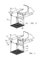
- FIG. 1 is a front side perspective view of the extended stabilizing platform showing the general arrangement of all components installed on a floating craft;
- FIG. 2 is a front side perspective view of the retracted stabilizing platform showing the general arrangement of all components installed on a floating craft;
- FIGS. 3-6 are a series of time staggered illustrations showing the steps required to raise and lock the platform
- FIG. 3 is a front side perspective view of the extended stabilizing platform lowered showing the general arrangement of all components
- FIG. 4 is a front side perspective view of the extended stabilizing platform lowered with the operating handles extended, showing the general arrangement of all components;
- FIG. 5 is a front side perspective view of the retracted stabilizing platform and the operating handle extended, showing the general arrangement of all components;
- FIG. 6 is a front side perspective view of the retracted stabilizing platform with the operating handle retracted, showing the general arrangement of all components;
- FIG. 7 is a front perspective view of the platform locked in the fully extended position
- FIG. 8 is a front perspective view of the platform unlocked from the fully extended position and with the platform partially raised;
- FIGS. 9-12 are top, front, perspective and side views of the front mounting bracket assembly
- FIGS. 13-16 are a top, side, perspective and front views of the platform.
- FIG. 17 is a side perspective of the floating craft with the pontoons removed and the platform ready for raising.
- the floating craft stabilization platform 2 consists of a perforated, pivotable platform 4 , an optional universal fit front mounting assembly 6 , a platform lock assembly 8 , a pair of adjustable fabric straps 10 , an upper axle tube 12 , a lower axle tube 13 , an upper axle 15 a lower axle 17 , a pair of adjustable, pivotable legs 14 , a pair of lifting handles 16 , a safety bar 36 and a table 74 .
- the stabilizing platform 2 is a retrofit accessory designed to attach to the various configurations of floating craft frames presently on the market.
- the frame tubing used may be round, square or elliptical in cross section.
- the present design utilizes a pair of universal fit front mounting bracket assemblies 6 and an upper axle tube 12 that will accommodate the connection of the platform to the various configurations and dimensions of frame tubes.
- the platform is designed for use in salt, brackish or freshwater environments the components are rust and salt resistant by material and/or coating selection. In the preferred embodiment these are made of lightweight metal such as aluminum, although a UV resistant polymer would also be suitable as would be powder coated or stainless steel or galvanized metal.
- the front mounting bracket assembly 6 ( FIGS. 9-12 ) is made of an upper U shaped piece of channel 42 joined to a lower U shaped piece of channel 44 .
- One side of the lower channel 44 is affixed to the bottom of the upper channel 42 such that their linear axes are parallel, but the open face of their U shapes are perpendicular.
- a strap connector 46 extends from the bottom of the upper channel 42 .
- a set of U-bolts 48 are threadingly engaged with mating nuts 50 through orifices in the upper channel 42 so as to form two enclosed rings that allow the connection of the front mounting bracket assembly 6 to the floating craft frame members.
- the strap connector 46 may be utilized as a connection point for the straps 10 or not, as the straps may directly encircle the frame or may be situated so as to directly encircle the front mounting bracket assembly 6 when mounted on the frame.
- the front mounting bracket assembly 6 may be eliminated completely. This would be done when the user has no need for a safety bracket 36 .
- the straps 10 have their top end looped around the frame of the floating craft rather than around the front mounting bracket assembly 6 or around the strap connector 46 on the front mounting bracket assembly 6 . In all other aspects the straps 10 would function identically.
- the straps 10 are of a flexible fabric adapted for use in water that have their proximate ends looped through the strap connector 46 (or encircling the frame) and then enmeshed with an adjustment buckle 20 located on the straps between the distil and proximate ends.
- the perforated platform 4 is a generally rectangular, planar member with numerous perforations 5 formed there through to allow water to freely pass. ( FIGS. 13-16 ) Affixed to the front edge of the platform 4 is a pair of platform strap loops 7 through which the distil end of the strap 10 is attached. In another embodiment of connection, the two ends of the adjustable strap may just be joined at the buckle 20 . In either configuration, the front of the platform 4 may be raised or lowered by adjusting the amount of strap 10 that passes through the buckle 20 .
- FIGS. 7 and 8 it can be seen that under the seat, affixed to the pontoon boat's frame crossmember (shown in phantom) is the upper axle tube 12 .
- This tube may be welded or mechanically affixed to the crossmember by bolts or clamps.
- On the upper axle tube 12 extends a locking lever assembly made of a locking lever arm 24 that pivots about pivot pin 25 which is affixed to locking lever bracket 22 .
- the locking lever arm has a leg portion 28 that will extend through a slot cut in the upper axle tube 12 so as to reside within one of the alignable locking slots 32 cut in the upper axle 30 .
- the leg portion 28 will disengage from the upper axle 30 allowing the upper axle 30 to freely pivot within the upper axle tube 12 and raise or lower the two legs 14 .
- the platform 4 is of a generally planar configuration with a series of perforations 5 formed therethrough. At the front of the platform 4 is a pair of strap loops 7 that extend to allow passage of the strap 10 which suspends the front end of the platform 4 .
- the rear of the platform is pivotally attached to the legs 14 by the lower axle tube 13 , the lower axle 17 as described herein.
- the leg 14 is comprised of an inner leg member 36 which slidingly resides within outer leg member 38 so as to enable a telescopic style adjustment of leg 14 .
- Attached to the outer leg member 38 is a top guide 27 which keeps the handle 16 and the leg 14 parallel and adjacent at all times.
- An optional stabilizing brace 99 is affixed between inner leg members 36 .
- At the bottom of the inner leg members 36 are orifices that accept either end of a lower axle 17 for pivotal motion.
- the lower end of the inner leg members 36 resides within lower leg brackets comprised of an outer plate 62 and an inner plate 64 which reside parallel to each other and extend normally from the rear edge of platform 4 .
- the lower axle tube 13 is affixed at either end to one of the inner plates 64 and rotationally houses lower axle 17 which passes through an orifice in the inner plate (not visible) and an orifice in the outer plate 62 .
- the lower axle may be retained therein by a number of mechanical means including mushrooming the axle ends, pins, bolting arrangements, devises, and the like.
- This design enables pivoting movement of the platform 4 with respect to the legs 14 as the platform 4 is raised or lowered.
- the handle 16 is a linear member having a bottom guide 54 affixed thereto that is slidingly attached to the leg 14 by inserting the handle 16 first through the top guide 26 then sliding the inner leg member 36 (deattached) through the bottom guide 54 of the handle, then assembling the outer and inner leg members.
- a handle there are many embodiments of a handle possible as the handle 16 is but a lifting mechanism. It need not be rigidly or slidingly affixed to the leg 14 , rather it could be a cable or stay arrangement that serves simply as a mechanism to lift the leg 14 .
- Attachment of the stabilizing platform 2 requires the user to affix the front mounting bracket assemblies 6 to the tubular frame of the craft with the U bolts and mechanically affixing the upper axle tube 12 to the crossmember.
- FIGS. 3-6 in conjunction with FIGS. 7 and 8 , the operation of the platform 2 can best be illustrated.
- the platform 4 resides in the water below and in front of the floating craft's seat 18 .
- the actual depth of the platform 4 is determined by adjustments of the buckles 20 on the straps 10 and the telescopic extension or retraction of the inner leg member 36 from within outer leg member 38 .
- FIG. 3 The handles 16 are raised vertically and are constrained adjacent and parallel to the legs 14 by handle mounted bottom guides 54 and outer leg member mounted top guide 27 .
- FIG. 4 The handle portion of the locking lever arm 24 is raised so that the leg portion 28 will disengage from the upper axle 30 and allow upper axle 30 to freely pivot within the upper axle tube 12 and raise or lower the two legs 14 when the handles 16 are pushed forward and down (toward the waterline at the bow of the craft).
- Depth adjustment of the platform 4 is set to accommodate the leg length of the user such that they can easily return to a seated position and that the safety bar 36 ( FIG. 17 ) is between the knee and waist of the user.
- the platform 4 When the platform 4 is lowered the user may stand on it to cast his line in any direction. This stabilizes the craft as the user and platform assembly combined, now function as a ballast to keep the craft from tipping as the user turns to cast in different directions. It also allows functions as a rudder to keep the craft moving in line with the current in a river, creek or stream rather than moving directionally with the surface wind. In the case of lake usage, it prevents the craft from blowing about.
- the platform 4 and legs 12 whether retracted or extended serve as a ballast to help stabilize the floating craft.
- the perforated design of the platform 4 allows it to offer extreme resistance to movement of the attached craft by virtue of the resistance it offers to water flowing through the perforations as the craft attempts to pivot or move. This feature greatly enhances the stability and safety of the craft.
- a safety bar 36 which is pivotally and removeably affixed to the front bracket assembly 6 .
- This pivot connection and the lock on the other end of the safety bar 36 are well known in the art and are not illustrated.
- This safety bar serves to stabilize the frame and to prevent the user from falling forward out of the craft while standing on the platform 4 .
- a table pedestal support 70 On distal end of the safety bar 36 is a table pedestal support 70 that slidingly engages the pedestal 72 of the table 74 .
- This support is section of tubing with its inside dimensions larger than the outside dimensions of the similarly configured tubing of the table pedestal 72 .
- a wingbolt (not visible) engages a threaded recess in the table pedestal support 70 so as to frictionally engage the pedestal 72 within the table pedestal support 70 and set the height of the table 74 .
Landscapes
- Chemical & Material Sciences (AREA)
- Engineering & Computer Science (AREA)
- Combustion & Propulsion (AREA)
- Mechanical Engineering (AREA)
- Ocean & Marine Engineering (AREA)
- Life Sciences & Earth Sciences (AREA)
- Marine Sciences & Fisheries (AREA)
- Emergency Lowering Means (AREA)
Abstract
Description
Claims (12)
Priority Applications (1)
| Application Number | Priority Date | Filing Date | Title |
|---|---|---|---|
| US14/102,154 US9045200B1 (en) | 2013-12-10 | 2013-12-10 | Floating craft stabilizing platform |
Applications Claiming Priority (1)
| Application Number | Priority Date | Filing Date | Title |
|---|---|---|---|
| US14/102,154 US9045200B1 (en) | 2013-12-10 | 2013-12-10 | Floating craft stabilizing platform |
Publications (2)
| Publication Number | Publication Date |
|---|---|
| US9045200B1 true US9045200B1 (en) | 2015-06-02 |
| US20150158562A1 US20150158562A1 (en) | 2015-06-11 |
Family
ID=53190552
Family Applications (1)
| Application Number | Title | Priority Date | Filing Date |
|---|---|---|---|
| US14/102,154 Active - Reinstated 2034-01-10 US9045200B1 (en) | 2013-12-10 | 2013-12-10 | Floating craft stabilizing platform |
Country Status (1)
| Country | Link |
|---|---|
| US (1) | US9045200B1 (en) |
Cited By (4)
| Publication number | Priority date | Publication date | Assignee | Title |
|---|---|---|---|---|
| US10053196B2 (en) * | 2016-04-20 | 2018-08-21 | Lawrence Donald Sporing | Pontoon systems and methods |
| US10933950B1 (en) * | 2019-12-18 | 2021-03-02 | John Chaney | Modular recreational watercraft |
| US20210179238A1 (en) * | 2018-05-03 | 2021-06-17 | Guillermo CAMARENA-VAZQUEZ | A catamaran for a wheelchair |
| US11523596B1 (en) * | 2020-07-16 | 2022-12-13 | Tim Hallbeck | Fish catching device |
Families Citing this family (1)
| Publication number | Priority date | Publication date | Assignee | Title |
|---|---|---|---|---|
| US20140346835A1 (en) * | 2013-05-24 | 2014-11-27 | Scott David Baznik | Standing support apparatus |
Citations (3)
| Publication number | Priority date | Publication date | Assignee | Title |
|---|---|---|---|---|
| US1555589A (en) * | 1925-02-25 | 1925-09-29 | Farina Thomas La | Floating chair |
| US2010371A (en) * | 1934-08-15 | 1935-08-06 | Perri Antonio | Float |
| US2332009A (en) * | 1940-11-12 | 1943-10-19 | Perri Antonio | Float |
-
2013
- 2013-12-10 US US14/102,154 patent/US9045200B1/en active Active - Reinstated
Patent Citations (3)
| Publication number | Priority date | Publication date | Assignee | Title |
|---|---|---|---|---|
| US1555589A (en) * | 1925-02-25 | 1925-09-29 | Farina Thomas La | Floating chair |
| US2010371A (en) * | 1934-08-15 | 1935-08-06 | Perri Antonio | Float |
| US2332009A (en) * | 1940-11-12 | 1943-10-19 | Perri Antonio | Float |
Cited By (7)
| Publication number | Priority date | Publication date | Assignee | Title |
|---|---|---|---|---|
| US10053196B2 (en) * | 2016-04-20 | 2018-08-21 | Lawrence Donald Sporing | Pontoon systems and methods |
| US11008075B2 (en) | 2016-04-20 | 2021-05-18 | Lawrence Donald Sporing | Pontoon systems and methods |
| US11655006B2 (en) | 2016-04-20 | 2023-05-23 | Lawrence Donald Sporing | Pontoon systems and methods |
| US20210179238A1 (en) * | 2018-05-03 | 2021-06-17 | Guillermo CAMARENA-VAZQUEZ | A catamaran for a wheelchair |
| US11673632B2 (en) * | 2018-05-03 | 2023-06-13 | Guillermo CAMARENA-VAZQUEZ | Catamaran for a wheelchair |
| US10933950B1 (en) * | 2019-12-18 | 2021-03-02 | John Chaney | Modular recreational watercraft |
| US11523596B1 (en) * | 2020-07-16 | 2022-12-13 | Tim Hallbeck | Fish catching device |
Also Published As
| Publication number | Publication date |
|---|---|
| US20150158562A1 (en) | 2015-06-11 |
Similar Documents
| Publication | Publication Date | Title |
|---|---|---|
| US9045200B1 (en) | Floating craft stabilizing platform | |
| US7789035B1 (en) | Stabilizer and standing support for a kayak or canoe | |
| US9242703B2 (en) | Height-adjustable seat for watercraft | |
| US7021423B1 (en) | Ladder stand with adjustable implement rest and pivotally movable flip-up seat | |
| US7314399B2 (en) | Floating sportsman's blind | |
| US8181381B1 (en) | Compact flexible stand-up fish fighting harness set | |
| US6089652A (en) | Fish fighting apparatus | |
| US8522709B2 (en) | Wakeboard tower with sun cover and ski tow point | |
| US20040072484A1 (en) | U-shaped float tube with stabilizing frame | |
| US10065713B2 (en) | Adjustable kayak seat | |
| US20120079978A1 (en) | Adjustable railing apparatus for a vessel | |
| US8939103B2 (en) | Deployable assembly | |
| US7234408B1 (en) | Water sport tow attachment with recoil | |
| CA1138265A (en) | Flotation device for supporting a person in water | |
| US5597277A (en) | Personal flotation/transportation device | |
| US10412949B2 (en) | Gunwale mounted fishing stanchion | |
| US8932095B1 (en) | Stand-up paddle board outrigger system | |
| US10793233B1 (en) | Apparatus and method for adapting stand up paddleboards to stable recreational platforms | |
| EP3515800B1 (en) | Pivoting sea anchor system | |
| CA2988422A1 (en) | A trimaran single-person flat water fishing craft comprising dual operating stations and a double anchoring system | |
| US20110290845A1 (en) | Fishing pole support system | |
| US8430047B1 (en) | Personal watercraft stabilizer | |
| US6557481B1 (en) | Combined outrigger and fishing rod holder | |
| US20220167604A1 (en) | Boat fishing devices | |
| US11589567B2 (en) | Fishing rod holder |
Legal Events
| Date | Code | Title | Description |
|---|---|---|---|
| STCF | Information on status: patent grant |
Free format text: PATENTED CASE |
|
| MAFP | Maintenance fee payment |
Free format text: PAYMENT OF MAINTENANCE FEE, 4TH YR, SMALL ENTITY (ORIGINAL EVENT CODE: M2551) Year of fee payment: 4 |
|
| FEPP | Fee payment procedure |
Free format text: MAINTENANCE FEE REMINDER MAILED (ORIGINAL EVENT CODE: REM.); ENTITY STATUS OF PATENT OWNER: SMALL ENTITY |
|
| LAPS | Lapse for failure to pay maintenance fees |
Free format text: PATENT EXPIRED FOR FAILURE TO PAY MAINTENANCE FEES (ORIGINAL EVENT CODE: EXP.); ENTITY STATUS OF PATENT OWNER: MICROENTITY |
|
| PRDP | Patent reinstated due to the acceptance of a late maintenance fee |
Effective date: 20230711 |
|
| FEPP | Fee payment procedure |
Free format text: PETITION RELATED TO MAINTENANCE FEES FILED (ORIGINAL EVENT CODE: PMFP); ENTITY STATUS OF PATENT OWNER: MICROENTITY Free format text: PETITION RELATED TO MAINTENANCE FEES GRANTED (ORIGINAL EVENT CODE: PMFG); ENTITY STATUS OF PATENT OWNER: MICROENTITY Free format text: ENTITY STATUS SET TO MICRO (ORIGINAL EVENT CODE: MICR); ENTITY STATUS OF PATENT OWNER: MICROENTITY Free format text: SURCHARGE, PETITION TO ACCEPT PYMT AFTER EXP, UNINTENTIONAL (ORIGINAL EVENT CODE: M3558); ENTITY STATUS OF PATENT OWNER: MICROENTITY |
|
| MAFP | Maintenance fee payment |
Free format text: PAYMENT OF MAINTENANCE FEE, 8TH YEAR, MICRO ENTITY (ORIGINAL EVENT CODE: M3552); ENTITY STATUS OF PATENT OWNER: MICROENTITY Year of fee payment: 8 |
|
| STCF | Information on status: patent grant |
Free format text: PATENTED CASE |
|
| FP | Lapsed due to failure to pay maintenance fee |
Effective date: 20230602 |