US9042749B2 - Fixing device including heating body and overtemperature protector, image forming apparatus and fixing device heating unit therewith - Google Patents
Fixing device including heating body and overtemperature protector, image forming apparatus and fixing device heating unit therewith Download PDFInfo
- Publication number
- US9042749B2 US9042749B2 US13/628,680 US201213628680A US9042749B2 US 9042749 B2 US9042749 B2 US 9042749B2 US 201213628680 A US201213628680 A US 201213628680A US 9042749 B2 US9042749 B2 US 9042749B2
- Authority
- US
- United States
- Prior art keywords
- support member
- heating body
- fixing device
- heat
- pressure application
- Prior art date
- Legal status (The legal status is an assumption and is not a legal conclusion. Google has not performed a legal analysis and makes no representation as to the accuracy of the status listed.)
- Expired - Fee Related, expires
Links
- 238000010438 heat treatment Methods 0.000 title claims abstract description 105
- 230000001012 protector Effects 0.000 title claims abstract description 43
- 238000009792 diffusion process Methods 0.000 claims abstract description 65
- 229910052782 aluminium Inorganic materials 0.000 claims description 9
- XAGFODPZIPBFFR-UHFFFAOYSA-N aluminium Chemical group [Al] XAGFODPZIPBFFR-UHFFFAOYSA-N 0.000 claims description 9
- RYGMFSIKBFXOCR-UHFFFAOYSA-N Copper Chemical group [Cu] RYGMFSIKBFXOCR-UHFFFAOYSA-N 0.000 claims description 4
- 229910052802 copper Inorganic materials 0.000 claims description 4
- 239000010949 copper Substances 0.000 claims description 4
- 239000004519 grease Substances 0.000 claims description 4
- 239000010410 layer Substances 0.000 description 28
- XEEYBQQBJWHFJM-UHFFFAOYSA-N Iron Chemical compound [Fe] XEEYBQQBJWHFJM-UHFFFAOYSA-N 0.000 description 10
- 229920002379 silicone rubber Polymers 0.000 description 10
- 229910052751 metal Inorganic materials 0.000 description 8
- 239000002184 metal Substances 0.000 description 8
- 239000000956 alloy Substances 0.000 description 7
- 238000001514 detection method Methods 0.000 description 7
- 239000000463 material Substances 0.000 description 7
- 229910045601 alloy Inorganic materials 0.000 description 6
- 239000011347 resin Substances 0.000 description 6
- 229920005989 resin Polymers 0.000 description 6
- 239000010935 stainless steel Substances 0.000 description 6
- 229910001220 stainless steel Inorganic materials 0.000 description 6
- 239000004813 Perfluoroalkoxy alkane Substances 0.000 description 5
- 230000000694 effects Effects 0.000 description 5
- 229910052742 iron Inorganic materials 0.000 description 5
- 229920011301 perfluoro alkoxyl alkane Polymers 0.000 description 5
- PXHVJJICTQNCMI-UHFFFAOYSA-N Nickel Chemical compound [Ni] PXHVJJICTQNCMI-UHFFFAOYSA-N 0.000 description 4
- 230000004308 accommodation Effects 0.000 description 4
- 238000011156 evaluation Methods 0.000 description 4
- 229920001343 polytetrafluoroethylene Polymers 0.000 description 4
- 239000004810 polytetrafluoroethylene Substances 0.000 description 4
- YCKRFDGAMUMZLT-UHFFFAOYSA-N Fluorine atom Chemical compound [F] YCKRFDGAMUMZLT-UHFFFAOYSA-N 0.000 description 3
- 239000011737 fluorine Substances 0.000 description 3
- 229910052731 fluorine Inorganic materials 0.000 description 3
- 230000001681 protective effect Effects 0.000 description 3
- 239000002344 surface layer Substances 0.000 description 3
- 239000004642 Polyimide Substances 0.000 description 2
- XUIMIQQOPSSXEZ-UHFFFAOYSA-N Silicon Chemical compound [Si] XUIMIQQOPSSXEZ-UHFFFAOYSA-N 0.000 description 2
- XLOMVQKBTHCTTD-UHFFFAOYSA-N Zinc monoxide Chemical compound [Zn]=O XLOMVQKBTHCTTD-UHFFFAOYSA-N 0.000 description 2
- 230000015572 biosynthetic process Effects 0.000 description 2
- 229920001577 copolymer Polymers 0.000 description 2
- 229920001971 elastomer Polymers 0.000 description 2
- 229920001973 fluoroelastomer Polymers 0.000 description 2
- 239000011521 glass Substances 0.000 description 2
- 238000009413 insulation Methods 0.000 description 2
- 239000007769 metal material Substances 0.000 description 2
- 229910052759 nickel Inorganic materials 0.000 description 2
- 230000002093 peripheral effect Effects 0.000 description 2
- 229920001721 polyimide Polymers 0.000 description 2
- -1 polytetrafluoroethylene Polymers 0.000 description 2
- 229910052710 silicon Inorganic materials 0.000 description 2
- 239000010703 silicon Substances 0.000 description 2
- 239000000758 substrate Substances 0.000 description 2
- 229910000851 Alloy steel Inorganic materials 0.000 description 1
- VYZAMTAEIAYCRO-UHFFFAOYSA-N Chromium Chemical compound [Cr] VYZAMTAEIAYCRO-UHFFFAOYSA-N 0.000 description 1
- 239000002199 base oil Substances 0.000 description 1
- 239000000919 ceramic Substances 0.000 description 1
- 230000001276 controlling effect Effects 0.000 description 1
- 238000005516 engineering process Methods 0.000 description 1
- 230000008018 melting Effects 0.000 description 1
- 238000002844 melting Methods 0.000 description 1
- 239000003921 oil Substances 0.000 description 1
- SWELZOZIOHGSPA-UHFFFAOYSA-N palladium silver Chemical compound [Pd].[Ag] SWELZOZIOHGSPA-UHFFFAOYSA-N 0.000 description 1
- 239000000843 powder Substances 0.000 description 1
- 238000007639 printing Methods 0.000 description 1
- 230000001105 regulatory effect Effects 0.000 description 1
- 238000007650 screen-printing Methods 0.000 description 1
- 238000009751 slip forming Methods 0.000 description 1
- WFKWXMTUELFFGS-UHFFFAOYSA-N tungsten Chemical compound [W] WFKWXMTUELFFGS-UHFFFAOYSA-N 0.000 description 1
- 229910052721 tungsten Inorganic materials 0.000 description 1
- 239000010937 tungsten Substances 0.000 description 1
- 238000011144 upstream manufacturing Methods 0.000 description 1
- 239000011787 zinc oxide Substances 0.000 description 1
Images


Classifications
-
- G—PHYSICS
- G03—PHOTOGRAPHY; CINEMATOGRAPHY; ANALOGOUS TECHNIQUES USING WAVES OTHER THAN OPTICAL WAVES; ELECTROGRAPHY; HOLOGRAPHY
- G03G—ELECTROGRAPHY; ELECTROPHOTOGRAPHY; MAGNETOGRAPHY
- G03G15/00—Apparatus for electrographic processes using a charge pattern
- G03G15/20—Apparatus for electrographic processes using a charge pattern for fixing, e.g. by using heat
- G03G15/2003—Apparatus for electrographic processes using a charge pattern for fixing, e.g. by using heat using heat
- G03G15/2014—Apparatus for electrographic processes using a charge pattern for fixing, e.g. by using heat using heat using contact heat
- G03G15/2039—Apparatus for electrographic processes using a charge pattern for fixing, e.g. by using heat using heat using contact heat with means for controlling the fixing temperature
-
- G—PHYSICS
- G03—PHOTOGRAPHY; CINEMATOGRAPHY; ANALOGOUS TECHNIQUES USING WAVES OTHER THAN OPTICAL WAVES; ELECTROGRAPHY; HOLOGRAPHY
- G03G—ELECTROGRAPHY; ELECTROPHOTOGRAPHY; MAGNETOGRAPHY
- G03G15/00—Apparatus for electrographic processes using a charge pattern
- G03G15/20—Apparatus for electrographic processes using a charge pattern for fixing, e.g. by using heat
- G03G15/2003—Apparatus for electrographic processes using a charge pattern for fixing, e.g. by using heat using heat
- G03G15/2014—Apparatus for electrographic processes using a charge pattern for fixing, e.g. by using heat using heat using contact heat
- G03G15/2017—Structural details of the fixing unit in general, e.g. cooling means, heat shielding means
-
- G—PHYSICS
- G03—PHOTOGRAPHY; CINEMATOGRAPHY; ANALOGOUS TECHNIQUES USING WAVES OTHER THAN OPTICAL WAVES; ELECTROGRAPHY; HOLOGRAPHY
- G03G—ELECTROGRAPHY; ELECTROPHOTOGRAPHY; MAGNETOGRAPHY
- G03G2215/00—Apparatus for electrophotographic processes
- G03G2215/20—Details of the fixing device or porcess
- G03G2215/2003—Structural features of the fixing device
- G03G2215/2016—Heating belt
- G03G2215/2035—Heating belt the fixing nip having a stationary belt support member opposing a pressure member
Definitions
- a fixing device of the invention includes an endless belt that supplies heat to a medium, a heat diffusion member that stretches the endless belt, a heating body that heats the heat diffusion member, an overtemperature protector that is positioned to face the heating body; and a pressure application support member that is positioned between the heating body and the overtemperature protector.
- FIG. 4 is a cross-sectional view seen from a line A-A in FIG. 3 .
- FIGS. 8A and 8B are partial side views of a configuration of a fixing belt.
- FIG. 16 is a perspective view of a pressure application support member in the second embodiment.
- the toner image forming part 43 , the transfer part 44 and the fixing device 45 are positioned so that the toner image forming part 43 and the transfer part 44 are positioned on the upstream side and that the fixing device 45 is positioned on the downstream side in a carrying direction of the sheet 12 fed from the sheet accommodation part 40 .
- the toner image forming part 43 and the transfer part 44 are provided so as to face each other across a carrying path for the sheet 12 .
- the LED head 42 is positioned above the toner image forming part 43 .
- the sheet heating body 1 fits in the deeper side (upper side) of the indented part to surface-contact the heat diffusion member 3 .
- the pressure application support member 2 fits in the front side (lower side) of the indented part so that edges of the pressure application support member 2 contact the heat diffusion member 3 .
- the pressure application support member 2 is made of a metal with excellent heat conductivity and processability, such as aluminum, copper and the like; an alloy having such a metal as a main component; or an iron, iron-type alloys, stainless steel or the like with high heat durability and stiffness, and is formed in a plate form with uniform thickness.
- the pressure application support member 2 is not used in the conventional fixing device.
- the overtemperature protector 15 is a thermostat that detects a temperature and cuts off a power source that supplies electric power to the sheet heating body 1 when the detected temperature exceeds a certain temperature. In the present embodiment, the upper limit value of the operational temperature is 270° C.
- FIGS. 9A and 9B are perspective views of the heat diffusion member 3 .
- FIG. 9A shows an upper surface side
- FIG. 9B shows a lower surface side.
- the heat diffusion member 3 in the present embodiment has an arc cross-sectional shape, and the above-described indented part is formed on the lower surface side through the entire length of the heat diffusion member 3 in the longitudinal direction.
- the entire body of the heat diffusion member 3 is formed by a metal with high heat conductivity and excellent processability, such as aluminum, copper and the like; an alloy with such materials as main components; iron, iron-type alloys or stainless steel with high heat resistance and high stiffness; or the like.
- the heat diffusion member 3 and the sheet heating body 1 are made integral without any particular adhesion, as the heat diffusion member 3 is pressed against the sheet heating body 1 by the biasing force of the elastic member 8 .
- FIG. 10 is an exploded perspective view of the sheet heating body 1 .
- a ceramic heater, a stainless heater or the like is used for the sheet heating body 1 .
- an electric insulation layer 91 using a thin glass film is formed on a substrate 90 , such as SUS430, and a resistance heating body 93 is formed by applying a nickel chrome alloy or a silver-palladium allow powder in a paste form using screen printing.
- electrodes 94 are formed with a chemically stable metal with low electric resistance or a metal with a high melting point such as tungsten and the like.
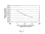
- the pressure application support member 2 is regulated in the above description by a range of the thickness.
- C 2 is a heat capacity of the pressure application support member 2
- a range of the heat capacity C 2 is preferably configured in a range of 11.75 J/K or greater and 24.2 J/K or less.
- C 1 is a heat capacity of the heat diffusion member 3
- the heat capacity C 2 is preferably configured at 30% or greater and 62% or less of the heat capacity C 1 .
- FIG. 11 is a side view of the fixing device (hereinafter referred to as a reference fixing device) illustrated for comparison with the first embodiment.
- the reference fixing device is configured similarly to the fixing device 45 of the first embodiment shown in FIG. 1 with exceptions that the pressure application support member 2 is removed from the fixing device 45 of the first embodiment, and that the overtemperature protector 15 directly abuts the sheet heating body 1 .
- the value a that corresponds to the boarder value is calculated by plugging the above-described design values in the below equation. T 2max ⁇ ( C 1 ⁇ T 1max)/( C 2 ⁇ )
- the heat conduction is made uniform in the longitudinal direction because the deformation by the external force and warping due to heat are prevented by forming the pressure application support member 16 in the U shape. Moreover, because of this, the uneven surface temperature of the fixing belt 4 is prevented. Therefore, there is an advantage that the fixing of the toner image without uneven gloss is achieved.
- the fixing device is explained that is installed in an electrographic printer as an image forming device. However, the above embodiments are also applicable in the multifunction peripheral (MPF), facsimile machines, photocopy machines and the like.
- MPF multifunction peripheral
Landscapes
- Physics & Mathematics (AREA)
- General Physics & Mathematics (AREA)
- Fixing For Electrophotography (AREA)
Abstract
Description
-
- fixing belt 4: Inner diameter being 45 mm; the base being of polyimide and having a thickness of 80 μm; elastic layer being silicon rubber and having a thickness of 150 μm; and releasing layer being of PFA and having a thickness of 30 μm
- Peripheral velocity of fixing belt 4: 60 mm/s
- fixing roller 6: φ=16, cored bar having C hardness of 80 degrees measured by ASKER; elastic layer being spongy silicon rubber and having a thickness of 1.5 mm
- Pressure application roller 7: (φ=36; cored bar having C hardness of 80 degrees measured by ASKER; elastic layer being spongy silicon rubber and having a thickness of 1.2 mm
- Pressure application member 5: Base material being a metal material, such as aluminum; elastic layer being silicon rubber having JIS-A hardness of 20 degrees and a thickness of 1 mm
- Pressure application force of pressure application member 5: 35 kg
- Sheet heating body 1: Stainless heater; width being 12 mm; 1200 W
- Heat diffusion member 3: Aluminum plate having thickness of 1 mm; heat capacity C1=39.1 J/K
- Nip part: Width (length) being 13 mm
T2max≧(C1×T1max)/(C2×α) (1)
where C1 is the heat capacity of the
T2max≧(C1×T1max)/(C2×α)
T2max≧(C1×T1max)/(C2×2.14) (2)
Claims (16)
T2max≧(C1×T1max)/(C2×α)
Priority Applications (1)
| Application Number | Priority Date | Filing Date | Title |
|---|---|---|---|
| US14/690,833 US9329539B2 (en) | 2011-09-28 | 2015-04-20 | Fixing device including heating body and protector and image forming apparatus |
Applications Claiming Priority (2)
| Application Number | Priority Date | Filing Date | Title |
|---|---|---|---|
| JP2011213544A JP5611921B2 (en) | 2011-09-28 | 2011-09-28 | Fixing apparatus and image forming apparatus |
| JP2011-213544 | 2011-09-28 |
Related Child Applications (1)
| Application Number | Title | Priority Date | Filing Date |
|---|---|---|---|
| US14/690,833 Continuation US9329539B2 (en) | 2011-09-28 | 2015-04-20 | Fixing device including heating body and protector and image forming apparatus |
Publications (2)
| Publication Number | Publication Date |
|---|---|
| US20130078018A1 US20130078018A1 (en) | 2013-03-28 |
| US9042749B2 true US9042749B2 (en) | 2015-05-26 |
Family
ID=47911453
Family Applications (2)
| Application Number | Title | Priority Date | Filing Date |
|---|---|---|---|
| US13/628,680 Expired - Fee Related US9042749B2 (en) | 2011-09-28 | 2012-09-27 | Fixing device including heating body and overtemperature protector, image forming apparatus and fixing device heating unit therewith |
| US14/690,833 Active US9329539B2 (en) | 2011-09-28 | 2015-04-20 | Fixing device including heating body and protector and image forming apparatus |
Family Applications After (1)
| Application Number | Title | Priority Date | Filing Date |
|---|---|---|---|
| US14/690,833 Active US9329539B2 (en) | 2011-09-28 | 2015-04-20 | Fixing device including heating body and protector and image forming apparatus |
Country Status (2)
| Country | Link |
|---|---|
| US (2) | US9042749B2 (en) |
| JP (1) | JP5611921B2 (en) |
Cited By (1)
| Publication number | Priority date | Publication date | Assignee | Title |
|---|---|---|---|---|
| US20150227094A1 (en) * | 2011-09-28 | 2015-08-13 | Oki Data Corporation | Fixing device and image forming apparatus |
Families Citing this family (10)
| Publication number | Priority date | Publication date | Assignee | Title |
|---|---|---|---|---|
| JP5674711B2 (en) * | 2012-05-31 | 2015-02-25 | 株式会社沖データ | Fixing apparatus and image forming apparatus |
| JP5812963B2 (en) * | 2012-10-01 | 2015-11-17 | 株式会社沖データ | Fixing apparatus and image forming apparatus |
| JP2015072395A (en) * | 2013-10-03 | 2015-04-16 | 富士ゼロックス株式会社 | Fixing device, and image forming apparatus |
| JP6198580B2 (en) * | 2013-11-18 | 2017-09-20 | キヤノン株式会社 | Image heating apparatus and image forming apparatus equipped with the image heating apparatus |
| JP6242181B2 (en) * | 2013-11-20 | 2017-12-06 | キヤノン株式会社 | Fixing device |
| JP5808451B2 (en) * | 2014-04-15 | 2015-11-10 | 株式会社沖データ | Fixing apparatus and image forming apparatus |
| JP6221997B2 (en) * | 2014-08-20 | 2017-11-01 | 京セラドキュメントソリューションズ株式会社 | Fixing apparatus and image forming apparatus |
| JP2016156951A (en) * | 2015-02-24 | 2016-09-01 | 株式会社沖データ | Belt unit and image forming apparatus |
| JP6456724B2 (en) | 2015-02-27 | 2019-01-23 | 株式会社沖データ | Image forming apparatus and fixing apparatus |
| KR102210406B1 (en) | 2017-12-18 | 2021-02-01 | 휴렛-팩커드 디벨롭먼트 컴퍼니, 엘.피. | Heater for fusing device having pairs of heating element and fusing device using the heater |
Citations (5)
| Publication number | Priority date | Publication date | Assignee | Title |
|---|---|---|---|---|
| JPH07199701A (en) | 1993-12-28 | 1995-08-04 | Canon Inc | Heating device |
| US6075228A (en) * | 1997-07-03 | 2000-06-13 | Canon Kabushiki Kaisha | Image heating device with bimetal thermoprotector |
| JP2004191514A (en) | 2002-12-09 | 2004-07-08 | Ricoh Co Ltd | Fixing device and image forming device |
| JP2007322888A (en) | 2006-06-02 | 2007-12-13 | Oki Data Corp | Fixing apparatus and image forming apparatus |
| US8412084B2 (en) * | 2009-11-30 | 2013-04-02 | Brother Kogyo Kabushiki Kaisha | Fixing device provided with temperature sensor |
Family Cites Families (1)
| Publication number | Priority date | Publication date | Assignee | Title |
|---|---|---|---|---|
| JP5611921B2 (en) * | 2011-09-28 | 2014-10-22 | 株式会社沖データ | Fixing apparatus and image forming apparatus |
-
2011
- 2011-09-28 JP JP2011213544A patent/JP5611921B2/en active Active
-
2012
- 2012-09-27 US US13/628,680 patent/US9042749B2/en not_active Expired - Fee Related
-
2015
- 2015-04-20 US US14/690,833 patent/US9329539B2/en active Active
Patent Citations (5)
| Publication number | Priority date | Publication date | Assignee | Title |
|---|---|---|---|---|
| JPH07199701A (en) | 1993-12-28 | 1995-08-04 | Canon Inc | Heating device |
| US6075228A (en) * | 1997-07-03 | 2000-06-13 | Canon Kabushiki Kaisha | Image heating device with bimetal thermoprotector |
| JP2004191514A (en) | 2002-12-09 | 2004-07-08 | Ricoh Co Ltd | Fixing device and image forming device |
| JP2007322888A (en) | 2006-06-02 | 2007-12-13 | Oki Data Corp | Fixing apparatus and image forming apparatus |
| US8412084B2 (en) * | 2009-11-30 | 2013-04-02 | Brother Kogyo Kabushiki Kaisha | Fixing device provided with temperature sensor |
Cited By (2)
| Publication number | Priority date | Publication date | Assignee | Title |
|---|---|---|---|---|
| US20150227094A1 (en) * | 2011-09-28 | 2015-08-13 | Oki Data Corporation | Fixing device and image forming apparatus |
| US9329539B2 (en) * | 2011-09-28 | 2016-05-03 | Oki Data Corporation | Fixing device including heating body and protector and image forming apparatus |
Also Published As
| Publication number | Publication date |
|---|---|
| US9329539B2 (en) | 2016-05-03 |
| JP2013073121A (en) | 2013-04-22 |
| JP5611921B2 (en) | 2014-10-22 |
| US20150227094A1 (en) | 2015-08-13 |
| US20130078018A1 (en) | 2013-03-28 |
Similar Documents
| Publication | Publication Date | Title |
|---|---|---|
| US9042749B2 (en) | Fixing device including heating body and overtemperature protector, image forming apparatus and fixing device heating unit therewith | |
| US10564579B2 (en) | Fixing apparatus | |
| JP6639180B2 (en) | Image heating device | |
| JP6476620B2 (en) | Fixing apparatus and image forming apparatus | |
| US9188916B2 (en) | Fuser and image forming apparatus | |
| JP6282141B2 (en) | Fixing device | |
| US9280109B2 (en) | Fixation device and image formation apparatus | |
| JP2008275756A (en) | Heat fixing device | |
| JP2011227377A (en) | Fixing device and image forming apparatus | |
| JP2010134094A (en) | Image heating device | |
| US9753429B2 (en) | Image heating apparatus | |
| JP6786697B2 (en) | Image heating device | |
| JP5808451B2 (en) | Fixing apparatus and image forming apparatus | |
| JP4810117B2 (en) | Image forming apparatus | |
| US9110417B2 (en) | Fixing apparatus and image forming apparatus including the fixing apparatus | |
| JP6740333B2 (en) | Fixing device | |
| JP2016004161A (en) | Fixing apparatus and image forming apparatus | |
| JP2016048323A (en) | Fixing rotator and fixing device | |
| JP7491069B2 (en) | Heating device and image forming apparatus | |
| JP7271134B2 (en) | image heating device | |
| JP2023086090A (en) | NIP FORMING UNIT AND IMAGE FORMING APPARATUS | |
| JP2008164770A (en) | Heating element and image forming apparatus | |
| JP2007328020A (en) | Image heating device | |
| JP2008170677A (en) | Heating element and image forming apparatus | |
| JP2009300775A (en) | Image heating apparatus |
Legal Events
| Date | Code | Title | Description |
|---|---|---|---|
| AS | Assignment |
Owner name: OKI DATA CORPORATION, JAPAN Free format text: ASSIGNMENT OF ASSIGNORS INTEREST;ASSIGNOR:YABUKI, RYOJI;REEL/FRAME:029038/0357 Effective date: 20120927 |
|
| STCF | Information on status: patent grant |
Free format text: PATENTED CASE |
|
| FEPP | Fee payment procedure |
Free format text: PAYOR NUMBER ASSIGNED (ORIGINAL EVENT CODE: ASPN); ENTITY STATUS OF PATENT OWNER: LARGE ENTITY |
|
| MAFP | Maintenance fee payment |
Free format text: PAYMENT OF MAINTENANCE FEE, 4TH YEAR, LARGE ENTITY (ORIGINAL EVENT CODE: M1551); ENTITY STATUS OF PATENT OWNER: LARGE ENTITY Year of fee payment: 4 |
|
| FEPP | Fee payment procedure |
Free format text: MAINTENANCE FEE REMINDER MAILED (ORIGINAL EVENT CODE: REM.); ENTITY STATUS OF PATENT OWNER: LARGE ENTITY |
|
| LAPS | Lapse for failure to pay maintenance fees |
Free format text: PATENT EXPIRED FOR FAILURE TO PAY MAINTENANCE FEES (ORIGINAL EVENT CODE: EXP.); ENTITY STATUS OF PATENT OWNER: LARGE ENTITY |
|
| STCH | Information on status: patent discontinuation |
Free format text: PATENT EXPIRED DUE TO NONPAYMENT OF MAINTENANCE FEES UNDER 37 CFR 1.362 |
|
| FP | Lapsed due to failure to pay maintenance fee |
Effective date: 20230526 |