US9032938B2 - In-cylinder charging system for fuel delivery systems and methods - Google Patents
In-cylinder charging system for fuel delivery systems and methods Download PDFInfo
- Publication number
- US9032938B2 US9032938B2 US13/626,716 US201213626716A US9032938B2 US 9032938 B2 US9032938 B2 US 9032938B2 US 201213626716 A US201213626716 A US 201213626716A US 9032938 B2 US9032938 B2 US 9032938B2
- Authority
- US
- United States
- Prior art keywords
- valve
- accumulator
- engine
- air
- compressed air
- Prior art date
- Legal status (The legal status is an assumption and is not a legal conclusion. Google has not performed a legal analysis and makes no representation as to the accuracy of the status listed.)
- Active, expires
Links
Images


Classifications
-
- F—MECHANICAL ENGINEERING; LIGHTING; HEATING; WEAPONS; BLASTING
- F02—COMBUSTION ENGINES; HOT-GAS OR COMBUSTION-PRODUCT ENGINE PLANTS
- F02M—SUPPLYING COMBUSTION ENGINES IN GENERAL WITH COMBUSTIBLE MIXTURES OR CONSTITUENTS THEREOF
- F02M67/00—Apparatus in which fuel-injection is effected by means of high-pressure gas, the gas carrying the fuel into working cylinders of the engine, e.g. air-injection type
- F02M67/02—Apparatus in which fuel-injection is effected by means of high-pressure gas, the gas carrying the fuel into working cylinders of the engine, e.g. air-injection type the gas being compressed air, e.g. compressed in pumps
-
- F—MECHANICAL ENGINEERING; LIGHTING; HEATING; WEAPONS; BLASTING
- F02—COMBUSTION ENGINES; HOT-GAS OR COMBUSTION-PRODUCT ENGINE PLANTS
- F02M—SUPPLYING COMBUSTION ENGINES IN GENERAL WITH COMBUSTIBLE MIXTURES OR CONSTITUENTS THEREOF
- F02M47/00—Fuel-injection apparatus operated cyclically with fuel-injection valves actuated by fluid pressure
- F02M47/02—Fuel-injection apparatus operated cyclically with fuel-injection valves actuated by fluid pressure of accumulator-injector type, i.e. having fuel pressure of accumulator tending to open, and fuel pressure in other chamber tending to close, injection valves and having means for periodically releasing that closing pressure
-
- F—MECHANICAL ENGINEERING; LIGHTING; HEATING; WEAPONS; BLASTING
- F02—COMBUSTION ENGINES; HOT-GAS OR COMBUSTION-PRODUCT ENGINE PLANTS
- F02B—INTERNAL-COMBUSTION PISTON ENGINES; COMBUSTION ENGINES IN GENERAL
- F02B33/00—Engines characterised by provision of pumps for charging or scavenging
- F02B33/02—Engines with reciprocating-piston pumps; Engines with crankcase pumps
- F02B33/06—Engines with reciprocating-piston pumps; Engines with crankcase pumps with reciprocating-piston pumps other than simple crankcase pumps
-
- F—MECHANICAL ENGINEERING; LIGHTING; HEATING; WEAPONS; BLASTING
- F02—COMBUSTION ENGINES; HOT-GAS OR COMBUSTION-PRODUCT ENGINE PLANTS
- F02D—CONTROLLING COMBUSTION ENGINES
- F02D41/00—Electrical control of supply of combustible mixture or its constituents
- F02D41/0025—Controlling engines characterised by use of non-liquid fuels, pluralities of fuels, or non-fuel substances added to the combustible mixtures
-
- F—MECHANICAL ENGINEERING; LIGHTING; HEATING; WEAPONS; BLASTING
- F02—COMBUSTION ENGINES; HOT-GAS OR COMBUSTION-PRODUCT ENGINE PLANTS
- F02M—SUPPLYING COMBUSTION ENGINES IN GENERAL WITH COMBUSTIBLE MIXTURES OR CONSTITUENTS THEREOF
- F02M25/00—Engine-pertinent apparatus for adding non-fuel substances or small quantities of secondary fuel to combustion-air, main fuel or fuel-air mixture
-
- F—MECHANICAL ENGINEERING; LIGHTING; HEATING; WEAPONS; BLASTING
- F02—COMBUSTION ENGINES; HOT-GAS OR COMBUSTION-PRODUCT ENGINE PLANTS
- F02M—SUPPLYING COMBUSTION ENGINES IN GENERAL WITH COMBUSTIBLE MIXTURES OR CONSTITUENTS THEREOF
- F02M49/00—Fuel-injection apparatus in which injection pumps are driven or injectors are actuated, by the pressure in engine working cylinders, or by impact of engine working piston
- F02M49/02—Fuel-injection apparatus in which injection pumps are driven or injectors are actuated, by the pressure in engine working cylinders, or by impact of engine working piston using the cylinder pressure, e.g. compression end pressure
-
- F—MECHANICAL ENGINEERING; LIGHTING; HEATING; WEAPONS; BLASTING
- F02—COMBUSTION ENGINES; HOT-GAS OR COMBUSTION-PRODUCT ENGINE PLANTS
- F02M—SUPPLYING COMBUSTION ENGINES IN GENERAL WITH COMBUSTIBLE MIXTURES OR CONSTITUENTS THEREOF
- F02M67/00—Apparatus in which fuel-injection is effected by means of high-pressure gas, the gas carrying the fuel into working cylinders of the engine, e.g. air-injection type
- F02M67/02—Apparatus in which fuel-injection is effected by means of high-pressure gas, the gas carrying the fuel into working cylinders of the engine, e.g. air-injection type the gas being compressed air, e.g. compressed in pumps
- F02M67/04—Apparatus in which fuel-injection is effected by means of high-pressure gas, the gas carrying the fuel into working cylinders of the engine, e.g. air-injection type the gas being compressed air, e.g. compressed in pumps the air being extracted from working cylinders of the engine
-
- F—MECHANICAL ENGINEERING; LIGHTING; HEATING; WEAPONS; BLASTING
- F02—COMBUSTION ENGINES; HOT-GAS OR COMBUSTION-PRODUCT ENGINE PLANTS
- F02N—STARTING OF COMBUSTION ENGINES; STARTING AIDS FOR SUCH ENGINES, NOT OTHERWISE PROVIDED FOR
- F02N19/00—Starting aids for combustion engines, not otherwise provided for
- F02N19/001—Arrangements thereof
-
- F—MECHANICAL ENGINEERING; LIGHTING; HEATING; WEAPONS; BLASTING
- F02—COMBUSTION ENGINES; HOT-GAS OR COMBUSTION-PRODUCT ENGINE PLANTS
- F02N—STARTING OF COMBUSTION ENGINES; STARTING AIDS FOR SUCH ENGINES, NOT OTHERWISE PROVIDED FOR
- F02N19/00—Starting aids for combustion engines, not otherwise provided for
- F02N2019/002—Aiding engine start by acting on fuel
Definitions
- the present disclosure is directed to fuel systems, and more particularly directed to providing compressed gas for fuel delivery systems that use multiple fluids to deliver fuel to an engine.
- stoichiometricity is a condition where the amount of oxidant required to completely burn a given amount of fuel is supplied in a homogeneous mixture resulting in optimally correct combustion with no residues remaining from incomplete or inefficient oxidation.
- the fuel should be completely vaporized, intermixed with air, and homogenized prior to ignition for proper oxidation.
- Non-vaporized fuel droplets do not ignite or combust completely in conventional internal and external combustion engines, which degrades fuel efficiency and increases engine out pollution.
- Some types of fuel delivery systems require a source of compressed air to properly delivery fuel to the cylinder for combustion.
- the compressed air is typically provided by the engine, a compressor component operated by the engine, or electrically off-board of the engine. Challenges exist related in providing a source of compressed air for the fuel delivery system when starting the engine before the compressor is operating.
- One aspect provides an air charging system that includes a valve providing access to an engine cylinder, an accumulator coupled in flow communication with the valve, and a controller operable to open and close the valve until a threshold pressure condition is reached in the accumulator.
- the valve may include a poppet valve.
- the poppet valve may be biased into a closed position.
- the controller may open the valve during a compression cycle during the engine start cycle.
- the controller may operate to control flow of compressed air stored in the accumulator to a fuel delivery system.
- the accumulator may include a storage tank.
- the accumulator may hold a volume of compressed air sufficient for at least one engine firing sequence.
- the valve may include a poppet valve opening in the cylinder that is arranged outward opening.
- the charging system may include a solenoid configured to move the valve between opened and closed positions.
- the method may also include closing the valve upon reaching a predetermined pressure condition in the accumulator.
- the method may include closing the valve upon completion of the engine compression stroke.
- the valve may include a valve opening directly into the cylinder, a valve seat positioned within the cylinder, and a poppet valve movable into and out of sealing contact with the valve seat.
- the method may include biasing the valve into a closed position.
- the method includes providing an air charging system and a fuel delivery system, wherein the air charging system includes a valve configured to access a power cylinder of the engine, and an accumulator connected in flow communication with the valve and the fuel delivery system.
- the method includes opening the valve during a compression cycle of the engine, collecting compressed air from the cylinder into the accumulator, delivering the compressed air from the accumulator to the fuel delivery system, and delivering fuel from the fuel delivery system to the cylinder to start the engine.
- the method may include closing the valve after completing the compression cycle of the engine.
- the method may include closing the valve after a predetermined pressure condition is reached in the accumulator.
- the method may include delivering the compressed air to the fuel delivery system only after a predetermined pressure condition is reached in the accumulator.
- the method may include shutting off the compressed air from the accumulator to the fuel delivery system after the engine is started.
- the method may further include using multiple compression cycles of the engine to reach the predetermined pressure condition in the accumulator.
- the method may also include providing a solenoid to operate the valve between opened and closed positions based on a compression cycle of the cylinder and a pressure condition in the accumulator.
- FIG. 1 is a schematic diagram showing an example air charging system in accordance with the present disclosure.
- FIG. 2 is a schematic diagram showing another example air charging system in accordance with the present disclosure.
- FIG. 3 is a schematic diagram showing another example air charging system in accordance with the present disclosure.
- FIGS. 5A and 5B are cross-sectional views of an example valve assembly in accordance with the present disclosure arranged in closed and open positions, respectively.
- FIG. 6 shows a flow diagram of an example functional strategy in accordance with the present disclosure.
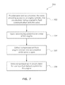
- FIG. 7 shows a flow diagram of another example functional strategy in accordance with the present disclosure.
- the present disclosure is directed to fuel preparation systems and methods, and related systems and methods for creating charged air that is used for the fuel preparation system.
- One type of fuel preparation system has a dual fluids input, wherein one of the fluids is gas (e.g., air) and the other fluid is a liquid (e.g., liquid fuel such as gasoline).
- a supply of the gas is needed to commence operation of the fuel preparation system in order to deliver a prepared fuel charge to the engine for starting the engine.
- a mechanically or electrically driven compressor may assume the task of providing a source of the compressed gas to the fuel preparation system.
- the supply of compressed gas prior to starting the engine may be provided using, for example, a charge accumulator tank, a converter, a reformer, or other charge supply device.
- An example air charging system in accordance with the present disclosure collects compressed air from a cylinder of the engine during a compression stroke of an initial engine rotation while the engine is cranking for startup.
- the compressed air is stored in an accumulator to provide sufficient air volume for operating the fuel preparation system to start the engine.
- At least one compression cycle may be required to sufficiently charge the air charging system to provide adequate air volume for starting the engine.
- Air pressure within the accumulator may be monitored during engine start cranking to determine when the firing sequence may commence (e.g., delivery of fuel from a fuel preparation system).
- an engine driven or off-engine compressor may assume responsibility for providing compressed air to the fuel preparation system.
- a variable displacement compressor may be applied at transient engine demand volumes—thus reducing parasitic losses at lower volumes.
- the example air charging systems disclosed herein may operate to scavenge gases (e.g., air) from a power cylinder of an engine during engine start cranking.
- gases e.g., air
- the scavenged compressed air may be used with a fuel preparation system such as a dual fluid injection system to start the engine.
- a fuel preparation system such as a dual fluid injection system to start the engine.
- An example air charging system in accordance with the present disclosure includes a charge valve assembly, an accumulator, a control valve and a controller (e.g., an engine control unit (ECU)).
- the charge valve assembly may include a valve member (e.g., a poppet valve) that provides access into a power cylinder combustion chamber of the engine. Compressed air is extracted from the engine power cylinder through the charge valve assembly during a compression cycle of the engine. The compressed air is stored in the accumulator.
- the charge valve assembly operates between open and closed positions to collect the compressed air from the engine power cylinder (typically during the compression stroke). Air may be collected from the power cylinder compression stroke in multiple cycles until a threshold pressure is reached in the accumulator.
- the controller then initiates an engine starting sequence in which compressed air from the accumulator is delivered to an air metering device that supplies compressed air to a fuel delivery device, which delivers fuel to the engine.
- the control valve switches from the accumulator to a compressor that operates under power of the engine, either mechanically or electrically, for supply of compressed air to the air metering device.
- FIG. 1 a schematic diagram of an example air charging system 10 is shown including a charge valve assembly 12 , an accumulator 14 , a control valve 16 , a compressor 18 , a one-way valve 20 , a controller 22 and an air metering device 24 .
- the charge valve assembly 12 provides flow of gases from the engine cylinder 30 .
- the gases accessed using the charge valve assembly 12 travel through the one-way valve 20 to the control valve 16 .
- the control valve 16 controls flow of the gases to the accumulator 14 .
- the accumulator 14 is coupled to the air metering device 24 .
- the air metering device 24 controls flow rate and pressure of the air delivered to fuel delivery device 26 .
- the air metering device 24 may include a regulator valve (e.g., a preset or variable valve).
- the regulator valve may be variable via, for example, the engine control unit (ECU) based on system parameters or duty cycle/demand.
- the fuel delivery device 26 uses the compressed air from air metering device 24 to generate a fuel charge and deliver the fuel charge to the engine 28 .
- the control valve 16 may operate between a position in which gases flow from the charge valve assembly 12 to the air metering device 24 and a position where air flows from the compressor 18 to the air metering device 24 .
- the controller 22 may control operation of a plurality of features of air charging system 10 .
- controller 22 may receive sensor signals from engine 28 related to a position of the piston in engine cylinder 30 to help determine when the charge valve assembly 12 should be operated between opened and closed positions.
- Sensor signals from the air system e.g., from sensor 329 on the air supply rail, manifold or other portion of the system as shown in FIG. 4A , which directly communicate air system information
- controller 22 may also be used by controller 22 to help determine, for example, when to initiate an ignition cycle by delivering compressed air from the air metering device 24 to the fuel delivery device 26 .
- the control valve 16 operates to provide flow of communication between accumulator 14 and compressor 18 only after the engine 28 has started and the compressor 18 is operating to generate compressed air.
- the charge valve assembly 12 includes a valve member 40 , a valve seat 42 , a valve opening 44 , a solenoid 46 , and a biasing member 48 .
- the valve member 40 includes a stem 50 and a head 52 .
- the head 52 seals against the valve seat 42 when the charge valve assembly 12 is in a closed position as shown in FIG. 5A .
- Operating the solenoid 46 moves the head 52 away from the valve seat 42 to permit flow of gases (e.g., air) through the valve opening 44 as shown in FIG. 5B .
- the biasing member 48 biases the head 52 into the closed position of FIG. 5A .
- the charge valve assembly 12 shown in FIGS. 5A and 5B is typically referred to as a poppet valve or poppet valve assembly.
- Other types of valves may be used in place of a poppet valve such as, for example, a rotary valve.
- Poppet valves typically provide the advantage of minimum weight requirement, a generally reliable seal at the interface of the head 52 and valve seat 42 , and a failure mode into a closed position by operation of the biasing member 48 . Further, the poppet valve does not require alteration of the combustion chamber geometry.
- the poppet valve opens into the combustion chamber in an outward direction, thereby permitting maximum air flow around the valve member 40 and through the valve opening 44 for use by the air charging system 10 . Further, the poppet valve may maintain a relatively tight seal when the engine is firing and the piston is moving because the top of the head 52 is forced back into the valve seat 42 .
- a sensor may be used to determine a position of the piston operating in engine cylinder 30 .
- the controller 22 operates the charge valve assembly 12 between closed and opened positions based on a position of the piston operating within engine cylinder 30 (e.g., a crank position).
- a plurality of sensors may be used, wherein one sensor indicates a crank position while another sensor determines which cycle the cylinder is in.
- the charge valve assembly 12 is operated into an open position during a compression stroke and is closed during the remaining crank positions.
- the charge valve assembly 12 may be opened and closed several times (e.g., an opening cycle) in order to obtain the amount of compressed air in accumulator 14 needed to operate the fuel delivery device 26 .
- the accumulator 14 may have any desired shape, size, and volume.
- the accumulator 14 may be a separately formed structure that is mounted outside of engine 28 .
- the accumulator 14 is integrated into the engine 28 , such as being formed (e.g., cast) into a portion of the engine block or head.
- FIG. 3 shows an example air charging system 200 that includes the accumulator 14 integrated into engine 28 .
- the accumulator 14 is provided as a separate component.
- At least one sensor may be associated with accumulator 14 to determine a pressure condition within the accumulator 14 .
- An example accumulator 14 may have a volume in the range of about 1 L to about 3 L, and more preferably about 2 L for a multicylinder engine of 4 cylinders.
- the control valve 16 may be, for example and without limitation, a three-way valve or a shuttle valve.
- a control valve 16 operates between a first position in which gases flow from the charge valve assembly 12 to accumulator 14 , and a second position in which the flow path from the charge valve assembly 12 to the accumulator 14 is closed and a separate flow path between the compressor 18 and the accumulator 14 is opened.
- the control valve 16 may be operated between the first and second positions based on, for example, a pressure condition sensed within accumulator 14 , an operating state of compressor 18 , and an operating condition of engine 28 .
- the compressor 18 may be a mechanically driven or electric compressor.
- a mechanically driven compressor 18 is typically operable after the engine 28 has started and is powered by engine 28 .
- An electric compressor may operate using power generated by engine 28 or may draw power from a different power source such as batteries that are independent of engine operation.
- Using a mechanically driven compressor 18 may provide a low cost, low weight, simple option for providing the minimum requirements for compressed air for the fuel delivery device 26 .
- the one-way valve 20 is positioned in the flow line between the charge valve assembly 12 and the accumulator 14 or control valve 16 .
- the one-way valve 20 helps prevent backflow of compressed air collected from the charge valve assembly 12 .
- the controller 22 may be part of an engine control unit (ECU).
- the controller 22 may receive inputs from a variety of sensors of the air exchange system 10 and engine 28 , and receive feedback concerning operation of various components of the air charging system 10 , fuel delivery device 26 and engine 28 .
- the controller 22 typically controls operation of the charge valve assembly 12 between opened and closed positions, controls operation of the control valve 16 between first and second positions, and controls delivery of compressed air stored in accumulator 14 or delivered from compressor 18 to the air metering device 24 .
- the controller 22 may provide other operations and related methods for the air charging system 10 .
- the air metering device 24 may regulate the flow rate and pressure condition of compressed air stored in the accumulator 14 that is delivered to the fuel delivery device 26 .
- the air metering device 24 provides a flow of air at a pressure of about 4 Bar/58 psi to about 6 Bar/87 psi and at a flow rate of about 2.2 kg/hr to about 22 kg/hr.
- the accumulator 14 may act as a buffer for the compressed air being delivered from either the charge valve assembly 12 or the compressor 18 to the air metering device 24 .
- compressed air supplied via the charge valve assembly 12 may be delivered to the accumulator 14 in short bursts collected during the compression cycle of the engine until a threshold pressure condition is reached in accumulator 14 .
- the compressor 18 may have a compressed air output that modulates based on, for example, an operating condition of engine 28 .
- the accumulator 14 may regulate or buffer the peak and valley pressures delivered from the source of air pressure (e.g., the engine cylinder 30 or compressor 18 ) so that conditions of the compressed air delivered to the air metering device 24 are relatively consistent.
- FIG. 3 shows an air charging system 200 in which the accumulator 14 is integrated as a portion or a component of engine 28 .
- other features or components of air charging system 200 may be integrated into engine 28 or combined with each other to provide, for example, a more compact, less complex system having fewer parts.
- FIGS. 4A and 4B show another example air charging system 300 that is similar in some respects to the schematic air charging system 10 described above with reference to FIG. 1 .
- Air charging system 300 includes first and second charge valve assemblies 312 A, 312 B, an accumulator 314 , a control valve 316 , a compressor 318 , an air metering device 324 (also referred to as a pressure regulator), and a pressure sensor 334 .
- the air charging system 300 may be connected to first and second fuel delivery devices 326 A, 326 B, which are mounted to an engine 328 .
- the compressor 318 may be a mechanical, engine driven compressor that operates to provide compressed air after the engine 328 is operating.
- the accumulator 314 is positioned in the line between control valve 316 and the first and second fuel delivery devices 326 A, 326 B.
- the first and second charge valve assemblies 312 A, 312 B are connected in flow communication with the control valve 316 .
- An initial step 402 of the method may include an initial pressure check within the accumulator 14 .
- a step 403 includes determining if the accumulator pressure is above a threshold pressure level, and if so the system may automatically move to the step of starting the engine 418 by delivering compressed air from the accumulator through the air metering device to a fuel delivery device. If the pressure condition of the accumulator is lower than the threshold level, a step 404 provides reading an engine position sensor to determine an engine position and cycle in a step 406 . The charge valve is open in a step 408 during a compression cycle of the engine.
- Further steps of the method 400 may include operating the control valve after the engine starts to receive compressed air from a compressor (e.g., a mechanical or electric compressor), which is operated using power from the engine.
- a compressor e.g., a mechanical or electric compressor
- the compressed air provided by the compressor may be used to operate the fuel delivery device to continue operation of the engine.
- the air charging systems disclosed herein may be used as back-up systems for the compressor after the engine has started.
- the compressor may malfunction during operation of the engine.
- the controller of the air charging system may identify that the compressor has malfunctioned (e.g., senses a drop in pressure supplied to the fuel delivery device via the air metering device), and switch the control valve 16 to receive compressed air from the charge valve assembly for ongoing operation of the engine.
- another example functional strategy or method 500 in accordance with the present disclosure includes a first operational step 502 of providing a valve and an accumulator, wherein the valve provides access to an engine cylinder and the accumulator is coupled in fluid communication with the valve.
- a step 504 includes opening the valve during a compression stroke of the engine.
- a step 506 includes collecting compressed air from the engine cylinder into an accumulator while the valve is opened. The compressed air is stored in the accumulator for later use by a fuel delivery system for delivering fuel to the engine in a step 508 .
- the in-cylinder charge valve(s) and accumulator(s) may be used during braking to provide “regenerative braking” power by storing air compressed by the engine.
- the pressure buildup during compression into the accumulator provides engine braking, thus more efficient braking of the vehicle.
- the stored gas e.g., air
- the stored gas is then routed to a pneumatic motor or other air operated driveline component to provide vehicle launch or torque assist during higher torque demand modes thus reducing fuel consumption.
- the method may include forming (e.g., drilling) a valve opening and valve seat in the housing in which the engine cylinder is formed.
- the valve member is mounted to the engine and operable in the valve opening to control flow of gases from the engine cylinder 30 to the accumulator 14 .
- the accumulator 14 is coupled in flow communication with the air metering device 24 and the air metering device 24 is coupled in flow communication with the fuel delivery device 26 .
- the compressor 18 may also be coupled in flow communication with the air metering device 24 .
- a control valve may be positioned in the flow line between the charge valve and the accumulator, or between the accumulator and the air metering device as described above with reference to FIGS. 1 and 2 .
- One advantage associated with using the air charging systems disclosed herein is facilitating engine starting using the engine as an air pump during engine cranking, thereby eliminating the need for a separately powered air source during start up of the engine.
- Another potential advantage is mitigating the risks associated with attempting to store compressed air for use by a fuel delivery device during start up of an engine. Dissipation of stored air may result from permeability of the storage device or leaks in the system that may occur when the engine is not running. Dissipation of the stored air charge would other inhibit operation of a dual fluids fuel delivery device.
- the air charging systems disclosed herein may avoid reliance upon stored compressed air by collecting a volume of compressed air while cranking the engine during or just before starting.
- Another potential advantage relates to eliminating the need for an electrical pump to charge the accumulator or otherwise supply compressed air to the fuel delivery device prior to starting the engine. Avoiding the use of an electric pump may conserve battery capacity that may otherwise be needed for operation of the engine and other components such as components of a vehicle that carries the engine.
- a further potential advantage may relate to implementation of a mechanical, engine driven compressor pump to provide a source of compressed air after the engine is started.
- the use of a mechanical compressor pump may be advantageous where there is limited electrical load available.
- a still further potential advantage relates to the added functionality provided by the air charging system with relatively little or no increased reciprocating mass, parasitic load or inertia.
- a dual fluids system may be ideal for employing a variety of oxidants and mixtures tailored to a specific mission.
Landscapes
- Engineering & Computer Science (AREA)
- Chemical & Material Sciences (AREA)
- Combustion & Propulsion (AREA)
- Mechanical Engineering (AREA)
- General Engineering & Computer Science (AREA)
- Physics & Mathematics (AREA)
- Fluid Mechanics (AREA)
- Output Control And Ontrol Of Special Type Engine (AREA)
- Electrical Control Of Air Or Fuel Supplied To Internal-Combustion Engine (AREA)
- Filling Or Discharging Of Gas Storage Vessels (AREA)
- Fuel-Injection Apparatus (AREA)
Priority Applications (9)
| Application Number | Priority Date | Filing Date | Title |
|---|---|---|---|
| US13/626,716 US9032938B2 (en) | 2012-09-25 | 2012-09-25 | In-cylinder charging system for fuel delivery systems and methods |
| CN201380055912.2A CN104755719A (zh) | 2012-09-25 | 2013-09-09 | 用于燃料输送系统的气缸内充气系统和方法 |
| PCT/US2013/058701 WO2014051974A1 (en) | 2012-09-25 | 2013-09-09 | In-cylinder charging system for fuel delivery systems and methods |
| JP2015533093A JP6301338B2 (ja) | 2012-09-25 | 2013-09-09 | 燃料供給システムのためのシリンダー内給気システムおよびその方法 |
| EP13843003.8A EP2900954A4 (en) | 2012-09-25 | 2013-09-09 | CYLINDER INTERNAL CHARGING SYSTEM FOR FUEL FEEDING SYSTEMS AND METHOD |
| MX2015003798A MX2015003798A (es) | 2012-09-25 | 2013-09-09 | Sistema de carga en cilindro para sistemas y metodos de suministro de combustible. |
| IN2887DEN2015 IN2015DN02887A (https=) | 2012-09-25 | 2013-09-09 | |
| KR1020157010371A KR20150086241A (ko) | 2012-09-25 | 2013-09-09 | 연료 공급 시스템들 및 방법들을 위한 기통내 충전 시스템 |
| US14/694,941 US20150226164A1 (en) | 2012-09-25 | 2015-04-23 | In-cylinder charging system for fuel delivery systems and methods |
Applications Claiming Priority (1)
| Application Number | Priority Date | Filing Date | Title |
|---|---|---|---|
| US13/626,716 US9032938B2 (en) | 2012-09-25 | 2012-09-25 | In-cylinder charging system for fuel delivery systems and methods |
Related Child Applications (1)
| Application Number | Title | Priority Date | Filing Date |
|---|---|---|---|
| US14/694,941 Continuation US20150226164A1 (en) | 2012-09-25 | 2015-04-23 | In-cylinder charging system for fuel delivery systems and methods |
Publications (2)
| Publication Number | Publication Date |
|---|---|
| US20140083395A1 US20140083395A1 (en) | 2014-03-27 |
| US9032938B2 true US9032938B2 (en) | 2015-05-19 |
Family
ID=50337628
Family Applications (2)
| Application Number | Title | Priority Date | Filing Date |
|---|---|---|---|
| US13/626,716 Active 2033-05-28 US9032938B2 (en) | 2012-09-25 | 2012-09-25 | In-cylinder charging system for fuel delivery systems and methods |
| US14/694,941 Abandoned US20150226164A1 (en) | 2012-09-25 | 2015-04-23 | In-cylinder charging system for fuel delivery systems and methods |
Family Applications After (1)
| Application Number | Title | Priority Date | Filing Date |
|---|---|---|---|
| US14/694,941 Abandoned US20150226164A1 (en) | 2012-09-25 | 2015-04-23 | In-cylinder charging system for fuel delivery systems and methods |
Country Status (8)
| Country | Link |
|---|---|
| US (2) | US9032938B2 (https=) |
| EP (1) | EP2900954A4 (https=) |
| JP (1) | JP6301338B2 (https=) |
| KR (1) | KR20150086241A (https=) |
| CN (1) | CN104755719A (https=) |
| IN (1) | IN2015DN02887A (https=) |
| MX (1) | MX2015003798A (https=) |
| WO (1) | WO2014051974A1 (https=) |
Cited By (1)
| Publication number | Priority date | Publication date | Assignee | Title |
|---|---|---|---|---|
| US20180080424A1 (en) * | 2013-04-05 | 2018-03-22 | Enginetics, Llc | System control strategy and methods for multi-physics fluid atomizing |
Families Citing this family (2)
| Publication number | Priority date | Publication date | Assignee | Title |
|---|---|---|---|---|
| EP3559427B1 (en) * | 2016-12-22 | 2021-03-10 | Volvo Truck Corporation | A gas feeding arrangement |
| CN116505033B (zh) * | 2023-06-28 | 2023-12-22 | 佛山市清极能源科技有限公司 | 一种燃料电池空气系统泄漏诊断方法 |
Citations (19)
| Publication number | Priority date | Publication date | Assignee | Title |
|---|---|---|---|---|
| US2522456A (en) * | 1948-11-13 | 1950-09-12 | Mallory Marion | Internal-combustion engine |
| US2693311A (en) | 1952-05-16 | 1954-11-02 | Herbert J Kratzer | Combined engine and air compressor |
| US2696343A (en) * | 1953-06-15 | 1954-12-07 | Mallory Res Co | Internal-combustion engine with compressor |
| US2818931A (en) | 1956-03-19 | 1958-01-07 | Mallory Marion | Internal combustion engine |
| US2867375A (en) | 1949-01-14 | 1959-01-06 | Petersen Hans | Internal combustion engine-air compressor |
| US3963379A (en) * | 1973-06-11 | 1976-06-15 | Takahiro Ueno | Convertible engine-air compressor apparatus for driving a vehicle |
| US4210062A (en) * | 1976-07-12 | 1980-07-01 | Plesko Edward J | Air conversion for internal combustion engines |
| US4741164A (en) | 1985-10-15 | 1988-05-03 | Slaughter Eldon E | Combustion engine having fuel cut-off at idle speed and compressed air starting and method of operation |
| US5529549A (en) | 1994-09-21 | 1996-06-25 | Moyer; David F. | Hybrid internal combustion engine |
| US5997259A (en) | 1998-04-30 | 1999-12-07 | Navistar International Transportation Corp. | Electronic engine - air compressor system |
| US6109886A (en) * | 1997-10-02 | 2000-08-29 | Wabco Gmbh | Compressed-air supply installation with reduced idling power |
| US20030140911A1 (en) * | 2002-01-29 | 2003-07-31 | Jui-Yang Lo | Power enhancement control system for combustion engine |
| US20050166592A1 (en) * | 2004-02-03 | 2005-08-04 | Larson Gerald L. | Engine based kinetic energy recovery system for vehicles |
| US20070246008A1 (en) * | 2004-10-01 | 2007-10-25 | Knorr-Bremse Systeme Fuer Nutzfahrzeuge Gmbh | Method and device for increasing the torque of a reciprocating piston internal combustion engine, in particular of a diesel engine |
| US20100122687A1 (en) * | 2007-06-19 | 2010-05-20 | Knorr-Bremse Systeme Fuer Nutzfahrzeuge Gmbh | Method and Device for Increasing the Engine Brake Power of a Reciprocating Piston Internal Combustion Engine of a Vehicle, Particularly of a Diesel Engine |
| US20100270097A1 (en) | 2009-04-22 | 2010-10-28 | Amit Prakash | Pneumatic - ic engine based power management system for automobiles and the like |
| US20100307440A1 (en) * | 2008-02-28 | 2010-12-09 | Brunel University | Engine for an Air Hybrid Vehicle |
| US20110144894A1 (en) * | 2009-12-15 | 2011-06-16 | Gm Global Technology Operations, Inc. | Air Assist Start Stop Methods and Systems |
| US20110284652A1 (en) | 2010-05-20 | 2011-11-24 | Lytesyde, Llc | Multi-physics fuel atomizer and methods |
Family Cites Families (8)
| Publication number | Priority date | Publication date | Assignee | Title |
|---|---|---|---|---|
| DE3321813A1 (de) * | 1983-06-16 | 1984-10-11 | Daimler-Benz Ag, 7000 Stuttgart | Kraftstoffeinspritzanlage fuer eine mehrzylindrige brennkraftmaschine mit einer sich aus gemisch- und fluessigkeitsduese zusammensetzenden zerstaeubungsduese |
| CA1306394C (en) * | 1987-04-15 | 1992-08-18 | Peter William Ragg | Direct fuel injection systems |
| AUPO095096A0 (en) * | 1996-07-10 | 1996-08-01 | Orbital Engine Company (Australia) Proprietary Limited | Pressurising a gas injection type fuel injection system |
| DE19834852A1 (de) * | 1998-08-01 | 2000-02-03 | Daimler Chrysler Ag | Brennstoffzuführsystem für eine fremdgezündete Brennkraftmaschine |
| US6273037B1 (en) * | 1998-08-21 | 2001-08-14 | Design & Manufacturing Solutions, Inc. | Compressed air assisted fuel injection system |
| DE19838843A1 (de) * | 1998-08-27 | 2000-02-03 | Daimler Chrysler Ag | Brennstoffzuführsystem für eine fremdgezündete Brennkraftmaschine und Verfahren zum Betrieb des Brennstoffzuführsystems |
| DE602004004133T2 (de) * | 2004-09-28 | 2007-11-15 | Magneti Marelli Powertrain S.P.A. | Einlasskrümmer mit Luftbehälter für eine Brennkraftmaschine |
| WO2008067623A1 (en) * | 2006-12-06 | 2008-06-12 | Delphi Technologies, Inc. | Pneumatic cold start system for multifuel vehicles |
-
2012
- 2012-09-25 US US13/626,716 patent/US9032938B2/en active Active
-
2013
- 2013-09-09 EP EP13843003.8A patent/EP2900954A4/en not_active Withdrawn
- 2013-09-09 KR KR1020157010371A patent/KR20150086241A/ko not_active Withdrawn
- 2013-09-09 CN CN201380055912.2A patent/CN104755719A/zh active Pending
- 2013-09-09 IN IN2887DEN2015 patent/IN2015DN02887A/en unknown
- 2013-09-09 WO PCT/US2013/058701 patent/WO2014051974A1/en not_active Ceased
- 2013-09-09 JP JP2015533093A patent/JP6301338B2/ja active Active
- 2013-09-09 MX MX2015003798A patent/MX2015003798A/es unknown
-
2015
- 2015-04-23 US US14/694,941 patent/US20150226164A1/en not_active Abandoned
Patent Citations (19)
| Publication number | Priority date | Publication date | Assignee | Title |
|---|---|---|---|---|
| US2522456A (en) * | 1948-11-13 | 1950-09-12 | Mallory Marion | Internal-combustion engine |
| US2867375A (en) | 1949-01-14 | 1959-01-06 | Petersen Hans | Internal combustion engine-air compressor |
| US2693311A (en) | 1952-05-16 | 1954-11-02 | Herbert J Kratzer | Combined engine and air compressor |
| US2696343A (en) * | 1953-06-15 | 1954-12-07 | Mallory Res Co | Internal-combustion engine with compressor |
| US2818931A (en) | 1956-03-19 | 1958-01-07 | Mallory Marion | Internal combustion engine |
| US3963379A (en) * | 1973-06-11 | 1976-06-15 | Takahiro Ueno | Convertible engine-air compressor apparatus for driving a vehicle |
| US4210062A (en) * | 1976-07-12 | 1980-07-01 | Plesko Edward J | Air conversion for internal combustion engines |
| US4741164A (en) | 1985-10-15 | 1988-05-03 | Slaughter Eldon E | Combustion engine having fuel cut-off at idle speed and compressed air starting and method of operation |
| US5529549A (en) | 1994-09-21 | 1996-06-25 | Moyer; David F. | Hybrid internal combustion engine |
| US6109886A (en) * | 1997-10-02 | 2000-08-29 | Wabco Gmbh | Compressed-air supply installation with reduced idling power |
| US5997259A (en) | 1998-04-30 | 1999-12-07 | Navistar International Transportation Corp. | Electronic engine - air compressor system |
| US20030140911A1 (en) * | 2002-01-29 | 2003-07-31 | Jui-Yang Lo | Power enhancement control system for combustion engine |
| US20050166592A1 (en) * | 2004-02-03 | 2005-08-04 | Larson Gerald L. | Engine based kinetic energy recovery system for vehicles |
| US20070246008A1 (en) * | 2004-10-01 | 2007-10-25 | Knorr-Bremse Systeme Fuer Nutzfahrzeuge Gmbh | Method and device for increasing the torque of a reciprocating piston internal combustion engine, in particular of a diesel engine |
| US20100122687A1 (en) * | 2007-06-19 | 2010-05-20 | Knorr-Bremse Systeme Fuer Nutzfahrzeuge Gmbh | Method and Device for Increasing the Engine Brake Power of a Reciprocating Piston Internal Combustion Engine of a Vehicle, Particularly of a Diesel Engine |
| US20100307440A1 (en) * | 2008-02-28 | 2010-12-09 | Brunel University | Engine for an Air Hybrid Vehicle |
| US20100270097A1 (en) | 2009-04-22 | 2010-10-28 | Amit Prakash | Pneumatic - ic engine based power management system for automobiles and the like |
| US20110144894A1 (en) * | 2009-12-15 | 2011-06-16 | Gm Global Technology Operations, Inc. | Air Assist Start Stop Methods and Systems |
| US20110284652A1 (en) | 2010-05-20 | 2011-11-24 | Lytesyde, Llc | Multi-physics fuel atomizer and methods |
Non-Patent Citations (1)
| Title |
|---|
| PCT International Search Report for International Application No. PCT/US2013/058701, mailed Feb. 3, 2014 (2 pp.). |
Cited By (3)
| Publication number | Priority date | Publication date | Assignee | Title |
|---|---|---|---|---|
| US20180080424A1 (en) * | 2013-04-05 | 2018-03-22 | Enginetics, Llc | System control strategy and methods for multi-physics fluid atomizing |
| US10330069B2 (en) * | 2013-04-05 | 2019-06-25 | Enginetics, Llc | System control strategy and methods for multi-physics fluid atomizing |
| US11231003B2 (en) * | 2013-04-05 | 2022-01-25 | Enginetics, Llc | System control strategy and methods for multi-physics fluid atomizing |
Also Published As
| Publication number | Publication date |
|---|---|
| EP2900954A4 (en) | 2016-07-13 |
| WO2014051974A1 (en) | 2014-04-03 |
| US20140083395A1 (en) | 2014-03-27 |
| JP2015532961A (ja) | 2015-11-16 |
| US20150226164A1 (en) | 2015-08-13 |
| JP6301338B2 (ja) | 2018-03-28 |
| CN104755719A (zh) | 2015-07-01 |
| EP2900954A1 (en) | 2015-08-05 |
| IN2015DN02887A (https=) | 2015-09-11 |
| MX2015003798A (es) | 2016-02-05 |
| KR20150086241A (ko) | 2015-07-27 |
Similar Documents
| Publication | Publication Date | Title |
|---|---|---|
| US8327831B2 (en) | Dual fuel compression ignition engines and methods | |
| CA2538980C (en) | Method and apparatus for operating a dual fuel internal combustion engine | |
| US8887690B1 (en) | Ammonia fueled mobile and stationary systems and methods | |
| CN106246413B (zh) | 气体喷射组件、气体喷射组件的运行方法及内燃机 | |
| US20110251776A1 (en) | Fuel accumulator and fuel system using the same | |
| US11512654B2 (en) | Method for controlling injection in a combustion engine | |
| CN101137832A (zh) | 气体燃料直喷系统 | |
| US9032938B2 (en) | In-cylinder charging system for fuel delivery systems and methods | |
| JP2005307977A (ja) | ガス機関を運転する方法 | |
| US11231003B2 (en) | System control strategy and methods for multi-physics fluid atomizing | |
| US11808201B2 (en) | System, a method of controlling a system, and a vehicle comprising a system | |
| US20230019785A1 (en) | Fuel injection device for an internal combustion engine, in particular for a hydrogen combustion engine | |
| KR101509676B1 (ko) | 하이브리드 전기 자동차용 엔진 | |
| EP1489348A2 (en) | Method and apparatus for generating compressed air from liquefied air, for supplying compressed air to an engine | |
| CN113715601B (zh) | 一种组合动力装置 | |
| US20180355786A1 (en) | Control system and control method for an internal combustion engine | |
| EP4495413B1 (en) | Hydrogen fuel pressure energy recovery for hydrogen engine vehicles | |
| JP7837652B2 (ja) | 内燃機関 |
Legal Events
| Date | Code | Title | Description |
|---|---|---|---|
| AS | Assignment |
Owner name: ENGINETICS, LLC, FLORIDA Free format text: ASSIGNMENT OF ASSIGNORS INTEREST;ASSIGNORS:HARRIS, RODERICK;LULL, JOSEPH;WARNER, JUSTIN;REEL/FRAME:029023/0472 Effective date: 20120924 |
|
| AS | Assignment |
Owner name: ENGINETICS, LLC, FLORIDA Free format text: CORRECTIVE ASSIGNMENT TO CORRECT THE ASSIGNEE'S NAME ON PAGE 2 OF THE ORIGNIAL ASSIGNMENT PREVIOUSLY RECORDED ON REEL 029023 FRAME 0472. ASSIGNOR(S) HEREBY CONFIRMS THE TRANSFER O ASSIGNOR'S ENTRIE RIGHT, TITLE & INTEREST, INCL. THE RIGHT OF PRIORITY IN, TO AND UNDER APPLICATION NO. 13626716;ASSIGNORS:HARRIS, RODERICK;LULL, JOSEPH;WARNER, JUSTIN;SIGNING DATES FROM 20121210 TO 20121212;REEL/FRAME:029612/0219 |
|
| STCF | Information on status: patent grant |
Free format text: PATENTED CASE |
|
| MAFP | Maintenance fee payment |
Free format text: PAYMENT OF MAINTENANCE FEE, 4TH YR, SMALL ENTITY (ORIGINAL EVENT CODE: M2551); ENTITY STATUS OF PATENT OWNER: SMALL ENTITY Year of fee payment: 4 |
|
| MAFP | Maintenance fee payment |
Free format text: PAYMENT OF MAINTENANCE FEE, 8TH YR, SMALL ENTITY (ORIGINAL EVENT CODE: M2552); ENTITY STATUS OF PATENT OWNER: SMALL ENTITY Year of fee payment: 8 |
|
| AS | Assignment |
Owner name: V-STAX, LLC, FLORIDA Free format text: ASSIGNMENT OF ASSIGNORS INTEREST;ASSIGNOR:ENGINETICS, LLC;REEL/FRAME:072206/0444 Effective date: 20250718 |