US9032793B1 - Wheel balancer - Google Patents
Wheel balancer Download PDFInfo
- Publication number
- US9032793B1 US9032793B1 US13/432,922 US201213432922A US9032793B1 US 9032793 B1 US9032793 B1 US 9032793B1 US 201213432922 A US201213432922 A US 201213432922A US 9032793 B1 US9032793 B1 US 9032793B1
- Authority
- US
- United States
- Prior art keywords
- cable
- base
- wheel
- piston
- wheel balancer
- Prior art date
- Legal status (The legal status is an assumption and is not a legal conclusion. Google has not performed a legal analysis and makes no representation as to the accuracy of the status listed.)
- Active, expires
Links
Images


Classifications
-
- G—PHYSICS
- G01—MEASURING; TESTING
- G01M—TESTING STATIC OR DYNAMIC BALANCE OF MACHINES OR STRUCTURES; TESTING OF STRUCTURES OR APPARATUS, NOT OTHERWISE PROVIDED FOR
- G01M1/00—Testing static or dynamic balance of machines or structures
- G01M1/02—Details of balancing machines or devices
-
- G—PHYSICS
- G01—MEASURING; TESTING
- G01M—TESTING STATIC OR DYNAMIC BALANCE OF MACHINES OR STRUCTURES; TESTING OF STRUCTURES OR APPARATUS, NOT OTHERWISE PROVIDED FOR
- G01M1/00—Testing static or dynamic balance of machines or structures
- G01M1/02—Details of balancing machines or devices
- G01M1/04—Adaptation of bearing support assemblies for receiving the body to be tested
- G01M1/045—Adaptation of bearing support assemblies for receiving the body to be tested the body being a vehicle wheel
-
- G—PHYSICS
- G01—MEASURING; TESTING
- G01M—TESTING STATIC OR DYNAMIC BALANCE OF MACHINES OR STRUCTURES; TESTING OF STRUCTURES OR APPARATUS, NOT OTHERWISE PROVIDED FOR
- G01M1/00—Testing static or dynamic balance of machines or structures
- G01M1/12—Static balancing; Determining position of centre of gravity
-
- B—PERFORMING OPERATIONS; TRANSPORTING
- B60—VEHICLES IN GENERAL
- B60B—VEHICLE WHEELS; CASTORS; AXLES FOR WHEELS OR CASTORS; INCREASING WHEEL ADHESION
- B60B2320/00—Manufacturing or maintenance operations
- B60B2320/30—Balancing
-
- B—PERFORMING OPERATIONS; TRANSPORTING
- B60—VEHICLES IN GENERAL
- B60B—VEHICLE WHEELS; CASTORS; AXLES FOR WHEELS OR CASTORS; INCREASING WHEEL ADHESION
- B60B30/00—Means for holding wheels or parts thereof
Definitions
- the invention relates generally to the field of devices for balancing wheel and tire assemblies. Balancing a wheel and tire assembly, such as that used on aircraft and other vehicles, typically refers to placing weight on the wheel such that the assembly spins in use without causing vibration or uneven wear.
- the current invention relates specifically to an apparatus and method for use in determining where weight should be distributed about a wheel when balancing a wheel and tire assembly.
- a wheel balancer includes a cable, a piston, and a base.
- the piston has proximal and distal ends and a hollow interior area for passing the cable therethrough.
- the base similarly has proximal and distal ends and a hollow interior area for passing the cable therethrough.
- the piston is extendable and retractable relative to the base such that the piston distal end is movable toward and away from the base distal end.
- the cable passes through the piston interior area and the base interior area and is operatively coupled to the base.
- a restriction is along the hollow interior area of the piston; the restriction is movable with the piston and forms a pivot point for the cable.
- a wheel balancer includes a cable, a first member, and a second member.
- the cable has a support end for being fastened to a support.
- the first member has proximal and distal ends and a hollow interior area for passing the cable therethrough.
- the cable passes through the first member interior area and is operatively coupled to the first member such that a distance between the cable support end and the first member distal end is generally constant when the cable is extended.
- the second member is extendable and retractable relative to the first member such that a distal end of the second member is movable toward and away from the first member distal end.
- the cable passes through a hollow interior area of the second member.
- a restriction is along the hollow interior area of the second member; the restriction is movable with the second member and forms a pivot point for the cable. Structure is included for indicating orientation of the second member relative to the cable.
- a wheel balancer includes a cable and a base.
- the cable has a support end for being fastened to a support.
- the base is configured for receipt inside a wheel, and the base has proximal and distal ends and a hollow interior area for passing the cable therethrough.
- the cable passes through the base interior area and is operatively coupled to the base such that a distance between the cable support end and the base distal end is generally constant when the cable is extended.
- a pivot point for the cable is movable relative to the base between the base distal end and the cable support end.
- FIG. 1 is an isometric view of a wheel balancer according to an embodiment.
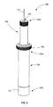
- FIG. 2 is a partial view of the wheel balancer of FIG. 1 .
- FIG. 3 is an exploded view of the wheel balancer of FIG. 1 .
- FIG. 4 a is a cross-sectional view of part of the wheel balancer of FIG. 1 , shown in use with a wheel and tire assembly.
- FIG. 4 b is a partial view taken from FIG. 4 a.
- Embodiments of the present invention provide wheel balancers and methods of using wheel balancers.
- FIGS. 1 through 4 b disclose a wheel balancer 100 that may be used to balance wheel and tire assemblies 10 , such as those used on aircraft and other vehicles.
- the wheel balancer 100 includes a cable 110 having a support end 110 a ( FIGS. 1 and 3 ) for being fastened to a support; a base 120 ( FIGS. 1-4 b ) having proximal and distal ends 120 a , 120 b ; and a pivot point 150 ( FIG. 4 b ) for the cable 110 that is movable relative to the base 120 between the base distal end 120 b and the cable support end 110 a .
- Means may be included for coupling the cable 110 to the support.
- a loop 112 may be formed at the cable support end 110 a
- a hook may be coupled to the cable support end 110 a
- any other appropriate fastening mechanisms may be utilized.
- the base 120 is configured for receipt inside a wheel of the wheel and tire assemblies 10 ( FIG. 4 b ) and may include an external lip 121 at the distal end 120 b .
- the base 120 may be configured for receipt specifically inside wheel bearings 12 .
- the base 120 may be constructed of metals (e.g., aluminum, steel, etc.), wood, plastics, composites, and/or other appropriate materials, and includes a hollow interior area 125 for passing the cable 110 therethrough.
- the cable 110 extends through the hollow interior area 125 and is operatively coupled to the base 120 .
- the cable 110 may be operatively coupled to the base 120 at the base distal end 120 b , and the cable 110 may be operatively coupled to the base 120 in various ways.
- a terminal end 110 b of the cable 110 may be seated in a complementary cavity 126 at the base distal end 120 b .
- a distance between the base distal end 120 b and the cable support end 110 a is generally constant when the cable 110 is extended.
- a second member (or “piston”) 140 having proximal and distal ends 140 a , 140 b is extendable and retractable relative to the base 120 such that the distal end 140 b is movable toward and away from the base distal end 120 b .
- the second member 140 may be extended and retracted relative to the base 120 in various ways; it may be particularly desirable, as shown in the drawings, for the members 120 , 140 to be slidable relative to one another (e.g., with the piston 140 extending inside the base 120 ).
- a snap ring 141 FIG. 3
- packing material, or other appropriate substances may aid in maintaining the position of the base 120 and the second member 140 constant relative to one another except for when adjustment is desired.
- the members 120 , 140 may be threadably connected or otherwise adjustable.
- the piston 140 has a hollow interior area 145 for passing the cable 110 therethrough, and the cable 110 passes through the interior area 145 .
- a restriction 150 along the hollow interior area 145 of the piston 140 is movable with the piston 140 and forms a pivot point for the cable 110 . While the restriction 150 may be at various locations along the interior area 145 , it may be particularly desirable for the restriction 150 to be at the distal end 140 b .
- the piston 140 may be constructed of metals (e.g., aluminum, steel, etc.), wood, plastics, composites, and/or other appropriate materials.
- Structure may be desirable for indicating orientation of the piston 140 (and the accompanying base 120 ) relative to the cable 110 .
- Various structure may be utilized, such as a circular opening 155 ( FIGS. 1 and 2 ). If a circular opening 155 is not used, indicia (e.g., crosshairs) on the structure may be particularly helpful in indicating orientation; however, indicia may be used with a circular opening 155 as well.
- the cable 110 may pass through a centerpoint of the circular opening 155 when the cable 110 extends linearly from the base distal end 120 b to past the piston proximal end 140 a.
- a retaining nut 160 (shown throughout the drawings) and bushings 170 ( FIGS. 1 , 3 , and 4 b ) may be included for handling and attachment purposes.
- the retaining nut 160 may, for example, be removably coupled to the base 120 adjacent the base proximal end 120 a , and may keep the base 120 in the wheel and tire assemblies 10 while handling.
- the bushings 170 may allow the base 120 to be used with wheel and tire assemblies 10 having different axle sizes, as described in further detail below.
- the wheel balancer 100 may initially appear as set forth in FIG. 1 .
- the retaining nut 160 is removed and the base 120 is passed through the wheel (in some embodiments, through the wheel bearings 12 and seals 14 ) such that the assembly 10 is coupled to the base 120 ; the retaining nut 160 may then be reattached.
- the retaining nut 160 may be removed, one of the bushings 170 may be slid over the base 120 , and the base 120 may be passed through the wheel (in some embodiments, through the wheel bearings 12 and seals 14 ).
- the second bushing 170 When in use with the wheel bearings 12 and seals 14 , the second bushing 170 may then be slid over the base 120 and through the seals 14 until a lip 171 of the bushing 170 contacts the wheel bearing 12 , and the retaining nut 160 may be reattached.
- the wheel and tire assembly 10 may generally include a brake disc or drum during balancing if the wheel is equipped with a brake disc or drum.
- the cable 110 may be suspended from any appropriate support (e.g., by the loop 112 ).
- the piston 140 may be raised to an uppermost position away from the base distal end 120 b , minimizing sensitivity in the wheel balancer 100 .
- weights may be added and distributed as needed to balance the wheel and tire assembly 10 . Balance is achieved when the cable 110 is centered in the circular opening 155 .
- the piston 140 may then be lowered toward the base distal end 120 b —causing the restriction 150 (and, thus, the pivot point for the cable 110 ) to move closer to the base distal end 120 b .
- Weights may again be added and distributed as needed to balance the wheel and tire assembly 10 , and balance is achieved when the cable 110 is centered in the circular opening 155 .
- the piston 140 may be successively lowered and weights may be added and distributed until the desired balance precision is achieved.
- the retaining nut 160 may be removed and the wheel and tire assembly 10 may be separated from the wheel balancer 100 .
- the weights may then be fixed to the wheel. To obtain the best dynamic balance results, it may be desirable for the weights to be evenly distributed between top and bottom surfaces.
- the wheel and tire assembly 10 may be reinstalled on the wheel balancer 10 to verify balance, and weights may be added or adjusted if needed.
Landscapes
- Physics & Mathematics (AREA)
- General Physics & Mathematics (AREA)
- Engineering & Computer Science (AREA)
- Aviation & Aerospace Engineering (AREA)
- Testing Of Balance (AREA)
Abstract
Description
Claims (20)
Priority Applications (1)
| Application Number | Priority Date | Filing Date | Title |
|---|---|---|---|
| US13/432,922 US9032793B1 (en) | 2012-03-06 | 2012-03-28 | Wheel balancer |
Applications Claiming Priority (2)
| Application Number | Priority Date | Filing Date | Title |
|---|---|---|---|
| US201213413398A | 2012-03-06 | 2012-03-06 | |
| US13/432,922 US9032793B1 (en) | 2012-03-06 | 2012-03-28 | Wheel balancer |
Related Parent Applications (1)
| Application Number | Title | Priority Date | Filing Date |
|---|---|---|---|
| US201213413398A Continuation | 2012-03-06 | 2012-03-06 |
Publications (1)
| Publication Number | Publication Date |
|---|---|
| US9032793B1 true US9032793B1 (en) | 2015-05-19 |
Family
ID=53054515
Family Applications (1)
| Application Number | Title | Priority Date | Filing Date |
|---|---|---|---|
| US13/432,922 Active 2033-09-15 US9032793B1 (en) | 2012-03-06 | 2012-03-28 | Wheel balancer |
Country Status (1)
| Country | Link |
|---|---|
| US (1) | US9032793B1 (en) |
Citations (13)
| Publication number | Priority date | Publication date | Assignee | Title |
|---|---|---|---|---|
| US2512231A (en) | 1945-09-29 | 1950-06-20 | Hart Henry | Balancing apparatus |
| US3992950A (en) | 1975-05-05 | 1976-11-23 | Theodore Joseph Pflieger | Wheel balancing device |
| US4051733A (en) | 1976-10-26 | 1977-10-04 | Sam Tomkin | Wheel balancing instrument |
| US4194399A (en) | 1978-10-05 | 1980-03-25 | Wilson E Robert | Wheel balancing tool |
| US4448073A (en) | 1982-06-28 | 1984-05-15 | Louison Patry | Wheel balancing device |
| US5097580A (en) * | 1990-07-02 | 1992-03-24 | Story Albert J | Apparatus for installing and removing valve stems |
| US5109213A (en) * | 1991-07-05 | 1992-04-28 | Williams John J | Tire pressure monitor |
| US5929334A (en) | 1998-04-30 | 1999-07-27 | Kautzky; Hans | Ultrasensitive balancing device for automotive wheels |
| US20050108871A1 (en) * | 2003-11-25 | 2005-05-26 | Sicam S.R.L. | Device for applying balancing weights to vehicle wheels in wheel balancing machines |
| US20050211965A1 (en) * | 2004-03-25 | 2005-09-29 | Korea Hoist Co., Ltd. | Safety device of air balancing hoist |
| US20080174166A1 (en) * | 2007-01-19 | 2008-07-24 | Russell John Kalil | Momentum management in a wheel such as a traction wheel under a changing load |
| US20080216567A1 (en) * | 2000-09-08 | 2008-09-11 | Automotive Technologies International, Inc. | Tire Monitoring System |
| US20140151169A1 (en) * | 2011-07-28 | 2014-06-05 | Robert H. Wehr | Inertial terrain transit event manager apparatus |
-
2012
- 2012-03-28 US US13/432,922 patent/US9032793B1/en active Active
Patent Citations (13)
| Publication number | Priority date | Publication date | Assignee | Title |
|---|---|---|---|---|
| US2512231A (en) | 1945-09-29 | 1950-06-20 | Hart Henry | Balancing apparatus |
| US3992950A (en) | 1975-05-05 | 1976-11-23 | Theodore Joseph Pflieger | Wheel balancing device |
| US4051733A (en) | 1976-10-26 | 1977-10-04 | Sam Tomkin | Wheel balancing instrument |
| US4194399A (en) | 1978-10-05 | 1980-03-25 | Wilson E Robert | Wheel balancing tool |
| US4448073A (en) | 1982-06-28 | 1984-05-15 | Louison Patry | Wheel balancing device |
| US5097580A (en) * | 1990-07-02 | 1992-03-24 | Story Albert J | Apparatus for installing and removing valve stems |
| US5109213A (en) * | 1991-07-05 | 1992-04-28 | Williams John J | Tire pressure monitor |
| US5929334A (en) | 1998-04-30 | 1999-07-27 | Kautzky; Hans | Ultrasensitive balancing device for automotive wheels |
| US20080216567A1 (en) * | 2000-09-08 | 2008-09-11 | Automotive Technologies International, Inc. | Tire Monitoring System |
| US20050108871A1 (en) * | 2003-11-25 | 2005-05-26 | Sicam S.R.L. | Device for applying balancing weights to vehicle wheels in wheel balancing machines |
| US20050211965A1 (en) * | 2004-03-25 | 2005-09-29 | Korea Hoist Co., Ltd. | Safety device of air balancing hoist |
| US20080174166A1 (en) * | 2007-01-19 | 2008-07-24 | Russell John Kalil | Momentum management in a wheel such as a traction wheel under a changing load |
| US20140151169A1 (en) * | 2011-07-28 | 2014-06-05 | Robert H. Wehr | Inertial terrain transit event manager apparatus |
Non-Patent Citations (3)
| Title |
|---|
| "McFarlane Aviation Products-Aircraft Wheel Balancer," Mar. 21, 2012, McFarlane Aviation Products, http://www.mcfarlaneaviation.com/Details.aspx?ID=54529635&Article=348; accessed on Feb. 9, 2015. * |
| "McFarlane Aviation Products—Aircraft Wheel Balancer," Mar. 21, 2012, McFarlane Aviation Products, http://www.mcfarlaneaviation.com/Details.aspx?ID=54529635&Article=348; accessed on Feb. 9, 2015. * |
| McFarlane ("McFarlane Aviation Wheel Balancer," Aug. 18, 2011, McFarlane Aviation, Inc., http://www.mcfarlane-aviation.com/pdfDocuments/TOOL108%20Instructions.pdf; accessed on Feb. 9, 2015). * |
Similar Documents
| Publication | Publication Date | Title |
|---|---|---|
| CN104828691B (en) | The stepless adjustable suspender of large-tonnage bias box beam | |
| US20140299726A1 (en) | Adjustable equipment support | |
| EP2935971B1 (en) | Spring balanced support device | |
| EP2778047A3 (en) | Damping arrangement for aircraft landing gear, for example a nosewheel | |
| CA2876700C (en) | Camera isolators and swing heads | |
| KR101652001B1 (en) | Spring-load type caster structure | |
| US20140008850A1 (en) | Camera platform horizontal axis shock and vibration isolator | |
| US9032793B1 (en) | Wheel balancer | |
| US20130327579A1 (en) | Method And Apparatus For Measuring The Weight Of A C-130 Aircraft With Jack-Screw Retraction Mechanism For The Main Landing Gear | |
| CN107963544A (en) | Hanging beam and suspender | |
| GB2539866A8 (en) | Wheel within the wheel | |
| EP2775281B1 (en) | Wheel balancing device | |
| CN105021410B (en) | Tire lip-off testing device | |
| EP3230619B1 (en) | Hingeless, large-throw negative stiffness structure | |
| US7544001B2 (en) | Balancing system for a camera crane | |
| EP4364631A3 (en) | A wheel support assembly for a floor surfacing machine | |
| US20230118117A1 (en) | Isolator Assembly with Adjustable Preload for Damping Air Load Forces | |
| US12343615B2 (en) | Skateboard truck with friction bushing | |
| CN103630124A (en) | Digital display centering device | |
| US5929334A (en) | Ultrasensitive balancing device for automotive wheels | |
| CN113202899A (en) | Airborne laser radar damping device | |
| CN110146248B (en) | Suspension mechanism for scaling model and vehicle scaling wind tunnel test equipment | |
| CN103154695B (en) | Anti-fall devices for two-wheeled vehicles | |
| US1832479A (en) | Tire balancing mechanism | |
| CN106968446B (en) | A special guardrail for building construction |
Legal Events
| Date | Code | Title | Description |
|---|---|---|---|
| AS | Assignment |
Owner name: HORIZON, LLC, KANSAS Free format text: ASSIGNMENT OF ASSIGNORS INTEREST;ASSIGNORS:MCFARLANE, DAVID A.;DUNN, MATTHEW SCOTT;REEL/FRAME:030230/0232 Effective date: 20120306 |
|
| STCF | Information on status: patent grant |
Free format text: PATENTED CASE |
|
| MAFP | Maintenance fee payment |
Free format text: PAYMENT OF MAINTENANCE FEE, 4TH YR, SMALL ENTITY (ORIGINAL EVENT CODE: M2551); ENTITY STATUS OF PATENT OWNER: SMALL ENTITY Year of fee payment: 4 |
|
| AS | Assignment |
Owner name: BMO HARRIS BANK N.A., AS ADMIN. AGENT, ILLINOIS Free format text: SECURITY AGREEMENT;ASSIGNOR:HORIZON, LLC;REEL/FRAME:057787/0758 Effective date: 20211012 |
|
| MAFP | Maintenance fee payment |
Free format text: PAYMENT OF MAINTENANCE FEE, 8TH YR, SMALL ENTITY (ORIGINAL EVENT CODE: M2552); ENTITY STATUS OF PATENT OWNER: SMALL ENTITY Year of fee payment: 8 |
|
| AS | Assignment |
Owner name: HORIZON, LLC, KANSAS Free format text: RELEASE OF SECURITY INTEREST;ASSIGNOR:BMO BANK N.A. (F/K/A BMO HARRIS BANK, N.A.);REEL/FRAME:074316/0701 Effective date: 20260407 |