US9032522B1 - PLC backplane analyzer for field forensics and intrusion detection - Google Patents
PLC backplane analyzer for field forensics and intrusion detection Download PDFInfo
- Publication number
- US9032522B1 US9032522B1 US13/947,887 US201313947887A US9032522B1 US 9032522 B1 US9032522 B1 US 9032522B1 US 201313947887 A US201313947887 A US 201313947887A US 9032522 B1 US9032522 B1 US 9032522B1
- Authority
- US
- United States
- Prior art keywords
- data
- controller
- operational
- baseline
- backplane
- Prior art date
- Legal status (The legal status is an assumption and is not a legal conclusion. Google has not performed a legal analysis and makes no representation as to the accuracy of the status listed.)
- Active, expires
Links
Images


Classifications
-
- G—PHYSICS
- G06—COMPUTING; CALCULATING OR COUNTING
- G06F—ELECTRIC DIGITAL DATA PROCESSING
- G06F21/00—Security arrangements for protecting computers, components thereof, programs or data against unauthorised activity
- G06F21/50—Monitoring users, programs or devices to maintain the integrity of platforms, e.g. of processors, firmware or operating systems
- G06F21/55—Detecting local intrusion or implementing counter-measures
- G06F21/552—Detecting local intrusion or implementing counter-measures involving long-term monitoring or reporting
Definitions
- controllers e.g., a programmable logic controller (PLC)
- I/O input/output
- gathering process information e.g., measurements, data, values, parameters, variables, metadata, etc.
- STUXNET attack As highlighted by the STUXNET attack, discovered in June 2010, process control operations, and PLCs in particular, have become a focus for malicious attack, such as a computer worm, virus or other malware.
- STUXNET attack involved a computer worm taking control of a PLC, the PLC was controlled to effect destruction of a component and/or apparatus while at the same time, the PLC was reporting that the component/apparatus was operating correctly.
- a contemporary approach for verification of PLC integrity can involve requesting content of the PLC firmware and/or logic over a network, whereby the integrity of the PLC can be remotely determined.
- traffic e.g., data, commands, etc.
- traffic can be examined as it flows into and/or out of a control network associated with the PLC.
- firmware/logic read-back approach and the traffic on the control network can be subverted.
- an analyzer system can be configured to compare operational data with baseline data, wherein the operational data is captured for an operational state for which the baseline data has been previously captured. In another embodiment, based at least in part upon the comparison, a determination can be made regarding whether there is an anomaly between content of the operational data and content of the baseline data. In an embodiment, the operational data and baseline data can be captured from a backplane.
- Another exemplary embodiment comprises a method for determination of unexpected and/or malicious activity occurring between components communicatively coupled across a backplane.
- the method comprising determining, based at least on comparing operational data with baseline data, whether there is an anomaly between content of the operational data and content of the baseline data, wherein the operational data is captured for an operational state for which the baseline data has been previously captured.
- the operational data and the baseline data can be captured across a backplane.
- a further exemplary embodiment for determination of unexpected and/or malicious activity occurring between components communicatively coupled across a backplane comprises a computer-readable medium comprising instructions that, when executed by a processor, cause the processor to perform acts comprising capturing baseline data and operational data, wherein the operational data is captured for an operational state for which the baseline data has been previously captured, the baseline data and the operational data being captured between a controller and at least one device in communication with the controller.
- the communication being via a backplane connecting the controller with the at least one device.
- a determining operation based at least on comparing the operational data with the baseline data, to determine whether there is an anomaly between content of the operational data and content of the baseline data.
- FIG. 1 is a block diagram illustrating exemplary embodiments for determination of unexpected and/or malicious activity occurring between components communicatively coupled across a backplane.
- FIG. 2 is a block diagram illustrating exemplary embodiments for determination of unexpected and/or malicious activity occurring between components communicatively coupled across a backplane.
- FIG. 3 is a block diagram illustrating an exemplary analyzer system for analysis of data being communicated on a backplane.
- FIG. 4 is a block diagram illustrating an exemplary capture component for interception and forwarding of data being communicated on a backplane.
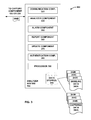
- FIG. 5 is a flow diagram illustrating an exemplary methodology for capturing an operational state baseline(s) of one or more devices connected to a backplane.
- FIG. 6 is a flow diagram illustrating an exemplary methodology for capturing operational data for one or more devices connected to a backplane.
- FIG. 7 is a flow diagram illustrating an exemplary methodology for selecting a diagnosis technique.
- FIG. 8 is a block diagram illustrating an exemplary configuration for a capture component in conjunction with a chassis and other components.
- FIG. 9 illustrates an exemplary computing device.
- the term “or” is intended to mean an inclusive “or” rather than an exclusive “or.” That is, unless specified otherwise, or clear from the context, the phrase “X employs A or B” is intended to mean any of the natural inclusive permutations. That is, the phrase “X employs A or B” is satisfied by any of the following instances: X employs A; X employs B; or X employs both A and B.
- the articles “a” and “an” as used in this application and the appended claims should generally be construed to mean “one or more” unless specified otherwise or clear from the context to be directed to a singular form.
- the term “exemplary” is intended to mean serving as an illustration or example of something, and is not intended to indicate a preference.
- Control data, instructions, measurements, and the like can be intercepted at a backplane where the backplane facilitates communication between a controller and at least one device.
- a copy of the control data can be made (e.g., the original control data can be replicated to generate a copy of the original control data).
- the original control data can continue on to either the controller or the at least one device, while the control data copy can be forwarded to an analyzer system to determine whether the control data contains unexpected content, e.g., a data anomaly.
- the content of the copy of the control data can be compared with a previously captured baseline data content, where the baseline data can be captured for a same operational state as the subsequently captured control data. Based on an anomaly being detected, a notification of the anomaly can be generated to facilitate the controller, at least one device, etc., associated with a process being controlled by the controller to be placed in a safe operating state.
- the content of a first control data instance can be compared with the content of a second control data instance to determine if there is a difference between the respective contents, whereby the second control data instance can act as a template to the first control data instance.
- FIG. 1 illustrates a process control configuration 100 in an industrial automation environment, according to an exemplary embodiment.
- a controller 110 is in communication, via backplane 130 , with one or more devices 140 A- 140 N, where N is a positive integer.
- Devices 140 A- 140 N can be any device associated with an operation controlled/monitored by controller 110 .
- devices 140 A- 140 N can be any of an I/O device, a controller, a sensor, an interface, a human machine interface (HMI), a graphical user interface (GUI), a device, a machine, a tool, a motor, a component, software, etc., to facilitate performing at least one operation in the industrial automation environment.
- HMI human machine interface
- GUI graphical user interface
- Capture component 120 can be utilized to capture data, information, a command, a command instruction, traffic, a control signal, etc. (hereinafter collectively referred to as “data” or “command instruction”), being conveyed across backplane 130 (e.g., between controller 110 and any of devices 140 A- 140 N) and along with facilitating conveyance of the data, across the backplane 130 , capture component 120 can also forward a copy of the data, to an analyzer system 150 .
- controller 110 can generate a command instruction 190 directed at device 140 B, with the command instruction 190 being initially conveyed on data-path 160 between controller 110 and capture component 120 .
- a command instruction 190 A can be forwarded by capture component 120 to device 140 B along data-path 170 .
- the sequence of content in the command instruction 190 can effectively be transmitted uninterrupted, as command instruction 190 A, to device 140 B.
- a replication of command instruction 190 can be generated at capture component 120 , whereupon the command instruction copy 190 B can be forwarded by capture component 120 to analyzer system 150 , e.g., via data path 180 .
- command instruction 190 B can be analyzed at analyzer system 150 to confirm that command instruction 190 B, and accordingly, command instruction 190 A, comprises expected content.
- Expected content can include any of a command, an instruction, a measurement, a setpoint, a device address, etc., as required to facilitate operation of one or more devices associated with controller 110 in the industrial automation environment.
- command instruction 190 B comprising expected content components included in process monitoring configuration 100 are considered to be operating correctly, e.g., firmware or logic of controller 110 has not been compromised.
- command instruction 190 B comprising unexpected content (e.g., an unexpected command directed to device 140 B)
- at least one component included in process monitoring configuration 100 can be considered to be operating incorrectly, e.g., firmware or logic of controller 110 has been compromised.
- FIG. 1 illustrates capture component 120 being located adjacent to backplane 130 (e.g., attached to backplane 130 ), capture component 120 can be located in any suitable location to facilitate operation of the various embodiments presented herein.
- capture component 120 can be co-located/incorporated into controller 110
- capture component 120 can be co-located/incorporated into backplane 130
- capture component 120 can be co-located/incorporated into any of devices 140 A- 140 N, etc.
- either of the capture component 120 or the analyzer system 150 can be interposed between the controller and the backplane thereby enabling either of the capture component 120 or the analyzer system 150 to act as a firewall or proxy device to regulate and/or validate behavior of any of the controller 110 , the backplane 130 , devices 140 A-N, etc.
- analyzer system 150 can be connected directly to capture component 120 to facilitate communication of data therebetween.
- analyzer system 150 can be connected to capture component 120 via the backplane 130 , whereby communication of data between capture component 120 and the analyzer system 150 is via backplane 130 .
- capture component 120 can be incorporated into analyzer system 150 , for example, analyzer system 150 may form part of a HMI or a GUI associated with the process control system, e.g., the HMI/GUI is operating on a machine, whereby the machine is being controlled at least in part by controller 110 which is in communication with capture component 120 .
- backplane 130 can be a shared backplane whereby a capture component (e.g., capture component 120 A) can be connected to backplane 130 and capture control data (e.g., command instruction 196 ) being transmitted between a controller (e.g., controller 110 A) connected directly to the backplane 130 .
- a capture component e.g., capture component 120 A
- capture control data e.g., command instruction 196
- controller 110 A can direct command instruction 196 directly to a device (e.g., any of devices 140 A-N), whereby command instruction 196 or return data 196 A from the device to controller 110 A can be captured by capture component 120 A.
- Command instruction 196 and/or return data 196 A can be replicated at capture component 120 A and forwarded as data 196 B to analysis system 150 .
- a plurality of capture components can be utilized in a process control/monitoring system, whereby each capture component can be operating directly with one or more controllers with data captured by each capture component being amalgamated at one or more analyzer systems to facilitate system-wide/process-wide monitoring in an industrial automation system.
- any command instruction and/or data being conveyed via network 175 can be transmitted in conjunction with a network component 198 , where network component 178 can be connected directly to backplane 130 (e.g., via a slot in a chassis associated with backplane 130 ) or network component 178 can be remotely connected.
- Capturing of data, etc., being conveyed on a network associated with one or more components comprising system 100 can supplement understanding of data (e.g., command instruction 190 or 196 ) being captured on the backplane 130 .
- controller 110 may have received instructional data which originated via network component 198 .
- controller 110 can generate a control instruction 190 for any of devices 140 A-N.
- controller 110 may have been compromised and generates data for transmission over network 175 . Analysis of the network based data can further understanding of how, when, etc., controller 110 may have been compromised.
- process monitoring configuration 200 includes a capture component 220 connected to a pair of configuration components 225 A and 225 B.
- Configuration components 225 A and 225 B can, in an embodiment, each operate as a protocol convertor(s), converting one or more protocols to a common protocol, as explained further below.
- Configuration component 225 A is connected, via data-path 260 A to controller 215
- configuration component 225 B is connected, via data-path 260 B to controller 210 .
- a plurality of manufacturers e.g., original equipment manufacturers (OEM's)
- OEMs original equipment manufacturers
- controllers 210 and 215 control components
- Each manufacturer can utilize their own proprietary control software/protocol, where a first proprietary control software may not be able to operate in conjunction with a second proprietary control software.
- controller 210 may be manufactured by a first OEM
- controller 215 may be manufactured by a second OEM, whereby the first OEM operating system may be incompatible with the second OEM operating system.
- one or more configuration components 225 A and 225 B can be incorporated into process monitoring configuration 200 to facilitate conversion of a proprietary control language to a common control language which can be analyzed at analyzer system 150 .
- configuration component 225 A can be utilized to convert operating instructions and data formatted in accordance with the second OEM operating system to a common format suitable for analysis by analyzer system 150
- configuration component 225 B can be utilized to convert operating instructions and data formatted in accordance with the first OEM operating system to the common format suitable for analysis by analyzer system 150 .
- configuration components 225 A and 225 B are illustrated as being separate from capture component 220 , the various embodiments presented herein are not so limited and one or more configuration components (e.g., any of configuration components 225 A and/or 225 B) can be located as required across process monitoring configurations 100 and 200 .
- the configuration component(s) can be incorporated into capture component 220 , or further incorporated into analyzer system 150 , etc.
- configuration components 225 A and 225 B are presented above facilitating conversion of data, etc., between a plurality of proprietary control software/protocols
- configuration components 225 A and 225 B can be configured in accordance with any situation requiring data to be converted from one protocol to another.
- configuration components 225 A and 225 B can be utilized to facilitate conversion from a first network protocol to a second network protocol to enable data to be transmitted between controller 110 and network component 198 .
- FIG. 3 illustrates an analyzer configuration 300 according to an exemplary embodiment.
- Analyzer configuration 300 can include an analyzer system 150 which can comprise of a plurality of components as described further herein.
- analyzer system 150 can be in communication with capture component 120 (or capture component 220 ), whereby analyzer system 150 can include a communication component 320 which be utilized to communicate with capture component 120 in accord with any communication protocol/format required to facilitate communication between analyzer system 150 and capture component 120 either directly, or via backplane 130 .
- a communication protocol/format can comprise of any of transmission control protocol (TCP), internet protocol (IP), a network protocol, a serial protocol, a parallel protocol, a hypertext transfer protocol (HTTP), an automation communication network protocol, common industrial protocol (CIP), a manufacturer specific protocol such as EtherNet/IP, Sinec H1, service request transport protocol (GE-SRTP), ControlNET, DeviceNET, peripheral component interconnect express (PCIe), RS-232, serial data interface (SDI-12), Modbus, etc.
- TCP transmission control protocol
- IP internet protocol
- HTTP hypertext transfer protocol
- CIP common industrial protocol
- EtherNet/IP Sinec H1
- GE-SRTP service request transport protocol
- ControlNET ControlNET
- DeviceNET deviceNET
- PCIe peripheral component interconnect express
- SDI-12 serial data interface
- Modbus Modbus
- Data received at analyzer system 150 can be stored, e.g., in data store(s) 340 .
- controller 110 can be operated in a number of ‘states’ to facilitate collection of baseline data, wherein the baseline data can act to identify communications (e.g., command instruction 190 B) that occurs between controller 110 and any other devices/components comprising process monitoring configuration 100 .
- baseline data e.g., baseline data 342 A- 342 N, where N is a positive integer
- capture component 120 can be captured (e.g., by capture component 120 ) and stored in data store(s) 340 .
- baseline data can be captured, hence in a first operational state baseline data 342 A is captured, in a second operational state baseline data 342 B is captured, in a third operational state baseline data 342 C is captured, in an Nth operational state baseline data 342 N is captured, etc.
- Each of the stored baseline data e.g., any of baseline data 342 A-N
- controller 110 may be issuing a command to a heater associated with device 140 A to increase a temperature of a furnace to a specific holding temperature, and thus baseline data (e.g., baseline data 342 A) captured during such an operational state of controller 110 can be identified as ‘furnace holding temperature’.
- controller 110 may be issuing a command to a motor associated with device 140 N to increase a speed of rotation from a first rotational velocity to a second rotational velocity to facilitate achievement of a particular operation, e.g., a milling operation, and thus baseline data (e.g., baseline data 342 N) captured during such an operational state of controller 110 can be identified as ‘milling speed’.
- any suitable identifier can be applied to a baseline data configuration, where the identifier can be alphanumeric, date, time, symbol, etc., to facilitate identification and hence, subsequent retrieval of a baseline data configuration (e.g., any of baseline data 342 A-N).
- content comprising baseline data 342 A-N can include any of a command, an instruction, a measurement, a setpoint, a device address, etc., as required to facilitate operation of one or more devices associated with controller 110 in the industrial automation environment 100 .
- controller 110 Upon subsequent operation of one or more components comprising an industrial automation environment, as one or more commands, etc., are generated by, or received at, controller 110 , (e.g., command instruction 190 ) a replication of the one or more commands can be generated by capture component 120 and forwarded to analyzer system 150 , e.g., capture component 120 forwards a copy 190 B of command instruction 190 to analyzer system 150 .
- each operational state can be identified to facilitate comparison of captured data with a baseline data, as stored in datastore 340 .
- Analyzer component 330 can be utilized to facilitate comparison of data comprising an operational state (e.g., command instruction 190 B) with baseline data (e.g., baseline data 342 C) captured during the initial configuration of controller 110 for a particular operational state.
- command instruction 190 B can be tagged with an identifier (e.g., as a header file, or the like) indicating the operational state of controller 110 during replication of command instruction 190 .
- Analyzer component 330 can review the command instruction 190 B identifier, and based thereon, retrieve a corresponding baseline data file.
- command instruction 190 B was captured during an operation to increase a furnace temperature and hence command instruction 190 B is tagged with an identifier ‘furnace holding temperature’, and based thereon, analyzer component 330 can facilitate retrieval of the previously stored baseline data 342 A, which continuing the prior example, also pertains to ‘furnace holding temperature’.
- an instance of data (e.g., a captured command instruction 190 B, any of baseline data 342 A-N) can be tagged with any information to facilitate comparison of captured data with baseline data, for example, each data instance can also have a date/timestamp associated therewith to facilitate identification by analyzer component 330 , or any other component, of when a particular instance of data was captured, e.g., to facilitate subsequent analysis (e.g., diagnostic analysis, forensic analysis, etc.) of operation of a particular device comprising an industrial control environment.
- each data instance can also have a date/timestamp associated therewith to facilitate identification by analyzer component 330 , or any other component, of when a particular instance of data was captured, e.g., to facilitate subsequent analysis (e.g., diagnostic analysis, forensic analysis, etc.) of operation of a particular device comprising an industrial control environment.
- Analysis of captured data (e.g., command instruction 190 B) with baseline data can be based on any suitable technique (e.g., an algorithm) such as a distance based technique, a support vector analysis, cluster analysis, etc., from which any anomaly of the captured data with the baseline data can be identified. Further, analysis can include parsing of the backplane data, displaying the backplane data (e.g., on a display associated with analyzer system 150 ), enabling an operator to filter the backplane data based on such techniques as sub-module addressing, message type, data conversation between devices, etc.
- any suitable technique e.g., an algorithm
- analysis can include parsing of the backplane data, displaying the backplane data (e.g., on a display associated with analyzer system 150 ), enabling an operator to filter the backplane data based on such techniques as sub-module addressing, message type, data conversation between devices, etc.
- analyzer component 330 can include further logic to facilitate further understanding of the anomaly.
- analyzer component 330 includes logic (e.g., artificial intelligence) that can facilitate selection of a technique from a plurality of available techniques (e.g., a statistical machine learning technique, a Bayesian classification, a neural network technique, a distance based technique, a similarity technique, a Chi Squared classifier technique, a support vector analysis, a cluster analysis, etc.) that is best able to identify the anomaly, one or more components or devices (e.g., controller 110 , I/O components 140 A-N) associated with the anomaly, etc. Based upon such technique selection identification and understanding of the anomaly can be expedited thereby facilitating timely understanding of an anomaly, the source of the anomaly, etc.
- a technique e.g., a statistical machine learning technique, a Bayesian classification, a neural network technique, a distance based technique, a similarity technique, a Chi Squared classifier technique, a support vector analysis, a cluster analysis, etc.
- datastore 340 As illustrated in FIG. 3 , as data is captured for a particular operational state of controller 110 (e.g., command instruction 190 B), the data can be stored in datastore 340 .
- datastore 340 has stored therein captured data 344 A- 344 N which have been captured in relation to one or more operational states of controller 110 , or other device in the process control configuration 100 of the industrial automation environment. Storage of previously captured data 344 A- 344 N can facilitate understanding of when an anomaly first occurred, for example.
- one or more components comprising process monitoring configuration 100 can be considered to be operating correctly, e.g., the firmware or the logic of controller 110 has not been compromised.
- command instruction 190 B is determined by analyzer component 330 to include at least one instance of unexpected content (e.g., an unexpected command directed to device 140 B)
- at least one component included in process monitoring configuration 100 can be considered by analyzer component 330 to be operating incorrectly, e.g., the firmware or the logic of controller 110 has been compromised.
- analyzer component 330 can initiate execution of an alarm, or other suitable notification, where the alarm can be generated by alarm component 350 .
- operation of a device e.g., device 140 B
- data being directed to controller 100 e.g., from device 140 B
- a report component 360 can be utilized to generate one or more reports relating to the operational performance of the one or more components included in the process control configuration 100 of the industrial automation environment. Any suitable report can be generated, such as a report identifying an instance of when an event of a component included in the process control configuration 100 is deemed by analyzer component 330 to be operating in a manner different to that defined in a baseline data configuration. In another embodiment, a report can be generated reporting operation of the one or more components incorporated into process control configuration 100 , where the operation can include at least one instance of correct operation, at least one instance of incorrect operation, or combination thereof.
- the report can be in any suitable format, e.g., include text, information in graphical form, an illustration, a diagram of the industrial automation environment indicating one or more components, devices, machines, etc., that are operating correctly/incorrectly, etc.
- a report can be generated in any suitable format, e.g., printed out, presented on a display device, stored as digital data, etc.
- Analyzer system 150 can further include an update component 370 .
- the control commands, instructions, machine settings, etc., for which one or more devices included in an automation environment are to operate may not change for a considerable amount of time. For example, once a manufacturing line is up and running no changes in operation of the one or more devices included in the automation environment may be made for an extended period of time, e.g., a day, a week, a month, etc. However, one or more of the devices may require an adjustment in operation.
- a different alloy maybe being utilized in the manufacturing process (e.g., the manufacturing process is a diecasting operation) and hence a different holding temperature is required to be configured at the furnace to facilitate holding the new alloy at the required temperature.
- controller 110 can be configured to subsequently issue a command instruction 190 which includes the new holding temperature.
- a copy of the command instruction 190 can be generated by capture component 120 and forwarded for storage as a new baseline data at analyzer system 150 .
- Updating of baseline data in data store 340 can, in an embodiment, be an operation of replacing a first instance of baseline data pertaining to an operational state with a second instance of baseline data pertaining to the operational state.
- updating of baseline data in data store 340 can be an operation of identifying a second instance of baseline data pertaining to an operational state with a different identifier to that utilized for a first instance of baseline data pertaining to the operational state.
- Update component 370 can be utilized to facilitate storage of a new baseline data in datastore 340 along with any required operations to facilitate utilization of an instance of baseline data associated with a new operational configuration.
- analyzer system 150 can further include an authentication component 380 .
- Authentication component 380 can be utilized to facilitate any operation relating to authentication, authorization and accounting (AAA) of operation of one or more components included in the process control configuration 100 .
- analyzer system 150 can be configured to operate with a particular AAA protocol, whereby only a particular individual(s) is able to access operation of analyzer system 150 .
- AAA authentication, authorization and accounting
- analyzer system 150 can be configured to operate with a particular AAA protocol, whereby only a particular individual(s) is able to access operation of analyzer system 150 .
- the individual upon initialization of analyzer system 150 , the individual has to enter a username and password to facilitate access to the analyzer system 150 .
- Numerous techniques are known in the art to facilitate AAA operation and are not expanded upon herein.
- a processor 390 can be utilized.
- each of components 320 - 380 can be formed from a self-contained electrical circuit (e.g., an integrated circuit) which a processor incorporated therein.
- processor 390 can execute instructions stored in datastore 340 (or other memory component). The instructions may be, for instance, instructions for implementing functionality described as being carried out by one or more components 320 - 380 as presented above, and as further described with reference to FIG. 8 .
- capture component 120 (or capture component 120 A) and/or analyzer system 150 can operate in a forensic manner.
- capture component 120 can also capture data being conveyed on backplane 130 and forward the data to the analyzer system 150 .
- baseline data e.g., baseline data 342 A-N
- capture component 120 can also capture data being conveyed on backplane 130 and forward the data to the analyzer system 150 .
- data being conveyed on backplane 130 can be captured and analyzed at analyzer system 150 without any baseline data having to be previously stored in datastore 340 .
- FIG. 4 illustrates an analyzer configuration 400 according to an exemplary embodiment.
- Analyzer configuration 400 can include a capture component 120 which can comprise of a plurality of components as described further herein.
- capture component 120 can be in communication with analyzer system 150 , whereby capture component 120 can include a communication component 410 which can be utilized to communicate with analyzer system 150 (e.g., via communication component 320 ) in accord with any communication protocol/format required to facilitate communication between capture component 120 and analyzer system 150 either directly, or via backplane 130 .
- capture component 120 can be utilized to replicate data conveyed across backplane 130 (e.g., between controller 110 and any of devices 140 A- 140 N) and along with facilitating conveyance of the data, etc., across the backplane 130 , capture component 120 can also forward a copy of the data, etc., to an analyzer system 150 .
- capture component 120 can intercept a command instruction 190 generated by controller 110 and directed, for example, at device 140 B, where the command instruction 190 is to be initially conveyed on data-path 160 between controller 110 and capture component 120 .
- the command instruction in the form of command instruction 190 A can continue from capture component 120 to device 140 B along data-path 170 . Further, upon receipt of the command instruction 190 at capture component 120 , a copy of command instruction 190 can be generated at capture component 120 , where the copy of command instruction 190 can be generated by replication component 420 , e.g., command instruction copy 190 B. Upon generation of the command instruction copy 190 B, the command instruction copy 190 B can be forwarded by capture component 120 to analyzer system 150 for analysis/storage of the command instruction copy 190 B by analyzer system, as previously described.
- Capture component 120 can further include an alarm component 430 which can be configured to operate in conjunction with alarm component 350 .
- alarm component 430 can receive from alarm component 350 , via communication components 320 and 410 , a notification that command instruction 190 B has been determined to include unexpected data and hence one or more devices comprising the automation process associated with controller 110 are deemed (e.g., by analyzer system 150 ) to have been compromised. Accordingly, an alarm can be activated, where such alarm can be an audible alarm, a visual alarm, etc. Further, an alarm notification can be forwarded to controller 110 to indicate to controller 110 that an associated process (e.g., operation of controller 110 , operation of any of devices 140 A-N, etc.) is deemed to have been compromised and appropriate action is to be implemented. Such action can be of any suitable type such as putting one or more devices associated with process control configuration 100 into a ‘safe’ operating mode, terminating operation of the one or more devices, terminating the process, etc.
- Capture component 120 can further include a processor 390 which can be configured to execute instructions stored in datastore 440 (or other memory component).
- the instructions may be, for instance, instructions for implementing functionality described as being carried out by one or more components 410 - 440 as presented above, and as further described with reference to FIG. 8 .
- a removable memory 450 can be incorporated into capture component 120 to facilitate storage of any of baseline data 440 A- 440 N and captured data 445 A- 445 N, whereby memory 450 can be subsequently removed, e.g., as part of a diagnostic operation.
- a capture component e.g., capture component 120 or 120 A
- a capture component can operate as an intrusion prevention system, which for example, in conjunction with analyzer system 150 , can capture data being generated by a controller (e.g., controller 110 ) prior to the data being received at any of devices 140 A-N.
- An intrusion component 470 can be incorporated into capture component 120 , wherein the intrusion component 470 can be configured to capture particular data prior to the data being transmitted across control system 100 .
- analyzer component 330 of analyzer system 150 can receive an instruction to prevent data of a known configuration (e.g., data associated with a known malicious attack) from being transmitted from controller 110 across the control system 100 .
- data of a known configuration e.g., data associated with a known malicious attack
- existence of the potentially malicious data can be indicated by capture component 120 to analyzer system 150 (e.g., a notification is sent, the captured data is forwarded, etc.) and further, alarm component 430 can be executed to facilitate further indication of the potentially malicious data being determined to exist.
- FIGS. 5-7 illustrate exemplary methodologies relating to determination of unexpected and/or malicious activity occurring between components communicatively coupled across a backplane. While the methodologies are shown and described as being a series of acts that are performed in a sequence, it is to be understood and appreciated that the methodologies are not limited by the order of the sequence. For example, some acts can occur in a different order than what is described herein. In addition, an act can occur concurrently with another act. Further, in some instances, not all acts may be required to implement the methodologies described herein.
- FIG. 5 illustrates an exemplary methodology 500 for determining unexpected and/or malicious activity occurring between components communicatively coupled via a backplane.
- a capture component can be configured for operation on a backplane.
- configuration account can be taken of the communication protocol(s) that may be being utilized between various components comprising an industrial automation process into which the capture component is to be incorporated.
- a capture component can include the necessary hardware, firmware, logic, etc., to facilitate conveyance of data between a controller component, and at least one device operating in conjunction with the controller component, whereby the controller component and the at least one device are connected to, and communicating via, a backplane.
- a capture component can be operating in conjunction with a configuration component, whereby the configuration component facilitates conversion of one or more protocols/formats as required to facilitate conveyance of data between a controller component and any other device communicatively coupled to the controller component via a backplane. Further, the capture component and/or the configuration component can enable protocol conversion to facilitate transmission of data between the capture component and an analyzer system to facilitate analysis of data being communicated on the backplane.
- the capture component can be incorporated into a process control and monitoring system.
- the capture component can be incorporated into the system at any suitable location to facilitate interception of data being conveyed between various components comprising an automation system which includes the process control and monitoring system.
- the capture component can be located on a backplane where the backplane is conveying data between a controller component and a device (e.g., an I/O device) associated with operation of a machine, engine, tool, etc., whereby the controller component is configured to control the machine, etc.
- the capture component can be located in the controller component facilitating interception of data being generated and/or received by the controller component.
- an analyzer system can be incorporated into the process control system, whereby the analyzer system can be utilized to review, and further diagnose, data being transmitted between components associated with the backplane.
- the analyzer system can be connected directly to the capture component to facilitate communication of data therebetween.
- the analyzer system can be connected to the capture component via the backplane, whereby communication of data between the capture component and the analyzer system is via the backplane.
- the capture component can be incorporated into the analyzer system, for example, the analyzer system may form part of a HMI or a GUI associated with the process control system, e.g., the HMI/GUI is operating on a machine, whereby the machine is being controlled at least in part by the controller component which is in communication with the capture component.
- the controller can be stepped through a number of operational states (e.g., ‘furnace holding temperature’, ‘milling speed’, etc.) and data which is conveyed, via the backplane, to a device (e.g., an I/O device) can be intercepted and a copy made of the data, and subsequently, a copy of the data can be forwarded to the analyzer system.
- a device e.g., an I/O device
- the copy of the data can act as a baseline identifying what content of the data is conveyed on the backplane during each operational state of the controller.
- each data copy can be stored at the analyzer system as baseline data for each operational state of the controller.
- each baseline data can be uniquely identified to facilitate storage and subsequent retrieval of the baseline data.
- the baseline data can act as a foundation against which data being conveyed on the backplane can be compared with during operation of the controller or other devices.
- FIG. 6 illustrates a methodology 600 for comparing operational data with baseline data to facilitate determination of unexpected and/or malicious activity occurring between components communicatively coupled via a backplane.
- baseline data can be captured and stored as reference data against which data captured during operation of the controller and any other devices can be compared against.
- data being communicated over the backplane can be captured for a given operational state of the process control/monitoring operation.
- the operational data can be intercepted by the capture component, while the operational data can be forwarded onto the receiving device, a copy of the operational data can be generated by the capture component and forwarded to the analyzer system.
- the previously stored baseline data can be retrieved for comparison with the newly captured operational data for the operational state.
- operation of the process associated with the controller component can be reviewed to ascertain whether the process is operating according to an expectation or the operational data contains data of which an equivalent data was not captured during the formation of the baseline data.
- a determination that the operational data comprises the same content as the baseline data a determination can be made that the process associated with the controller is operating in an expected manner and the flow returns to 610 in readiness for operational data for a subsequent operating state to be captured and analyzed.
- the flow can proceed to 640 , where a diagnosis operation can be performed to identify the difference between that operational data and the baseline data, and further, why the difference in content may have occurred.
- an alarm, or similar notification can be generated.
- an alarm notification can be generated by the analyzer component with the alarm activating a light, a speaker, etc. Further, the alarm notification can be forwarded to the controller to facilitate placing operation of the process associated with the controller into any of a safe operating state, close the process down, etc.
- a report can be generated indicating operation of the controller and any devices associated with a process being controlled by the controller.
- the report can present data reflecting any of expected operation of the controller and associated process(es), an anomaly between received data for a particular operational state versus a baseline data, or combination thereof.
- the report can be presented by any suitable technology such as in printed form, displayed on a display device, digitally stored, etc.
- FIG. 7 illustrates a methodology 700 for identifying an algorithm to facilitate in comparing operational data with baseline data.
- an analyzer system can be utilized to compare operational data for an operational state of a controller and/or associated process with baseline data previously captured for the operational state.
- an operational signal is captured for an operating state.
- an initial comparison can be performed, e.g., by an analyzer system, between the content of newly received operational data in comparison with content of previously received, baseline data.
- one or more techniques can be selected from a plurality of available techniques (e.g., distance based technique, a support vector analysis, cluster analysis, etc.), where a selected technique can facilitate identification of the anomaly, one or more components or devices (e.g., controller 110 , I/O components 140 A-N) associated with the anomaly, etc.
- Selection of a technique can be based on any suitable logic, such as artificial intelligence (AI), whereby the AI can review previously diagnosed anomaly instances and based thereon, can generate knowledge with regard to which technique(s) in the plurality of available techniques is best-suited in providing a diagnosis of the anomaly and other pertinent information (e.g., compromised machine, anomaly type, extent of the anomaly, etc.). Based upon such technique selection identification and understanding of the anomaly can be expedited thereby facilitating timely understanding of an anomaly, the source of the anomaly, etc.
- AI artificial intelligence
- an algorithm or other methodology associated with the selected technique(s) can be applied to the operational data, baseline data, combination thereof, etc., to facilitate understanding of the anomaly.
- FIG. 8 illustrates an exemplary configuration 800 of a capture component and other components for inclusion in a process monitoring system.
- Configuration 800 can include a PLC chassis 810 which further includes backplane 130 .
- the PLC chassis 810 can be constructed to support various modules as required for operation of a process.
- Backplane 130 can be incorporated into the PLC chassis 810 , whereby backplane 130 provides a communication path between the various I/O modules, a controller, a capture component, a controller, a processor, an I/O communication adapter module, etc.
- a capture component 120 can be incorporated into the chassis 810 (e.g., via a slot in chassis 810 ) with the capture component 120 in communication across the backplane 130 via backplane connector 840 .
- Capture component 120 can further include a system on a chip (SOC) component 850 which can include the necessary components to facilitate operation of the capture component 120 .
- SOC component 850 can include a processor 855 which can be utilized to perform one or more operations as required to facilitate operation of the capture component 120 .
- SOC component 850 can further include a field programmable gate array (FPGA) 860 which can be programmed as necessary to facilitate capture of data by the capture component 120 .
- Any suitable communication technology can be utilized to facilitate communication of data between the capture component 120 and any associated device/system (e.g., analysis system 150 ), where such communication technology can include packet data (e.g., via Ethernet connector 865 ) and serial communication (e.g., via serial connector 870 ).
- a processor module 875 can be co-located with the capture component 120 , including any of a processor module 875 , a communication module (e.g., Ethernet/IP module 880 ), a digital I/O module 885 and an analog I/O module 890 , as required to facilitate operation of the capture component 120 in a process control/monitoring system.
- a communication module e.g., Ethernet/IP module 880
- a digital I/O module 885 e.g., Ethernet/IP module 880
- an analog I/O module 890 e.g., Ethernet/IP module 880
- any suitable system for providing power to the various components comprising configuration 800 for example a power supply 895 can be incorporated into the PLC chassis 810 .
- the computing device 900 may be used in a system to determine unexpected and/or malicious activity occurring between components communicatively coupled across a backplane.
- the computing device 900 includes at least one processor 902 that executes instructions that are stored in a memory 904 .
- the instructions may be, for instance, instructions for implementing functionality described as being carried out by one or more components discussed above or instructions for implementing one or more of the methods described above.
- the processor 902 may access the memory 904 by way of a system bus 906 .
- the memory 2004 may also store operating parameters, required operating parameters, and so forth.
- the computing device 900 additionally includes a data store 908 that is accessible by the processor 902 by way of the system bus 906 .
- the data store 908 may include executable instructions, operating parameters, required operating parameters, etc.
- the computing device 900 also includes an input interface 910 that allows external devices to communicate with the computing device 900 .
- the input interface 910 may be used to receive instructions from an external computer device, from a user, etc.
- the computing device 900 also includes an output interface 912 that interfaces the computing device 900 with one or more external devices.
- the computing device 900 may display text, images, etc., by way of the output interface 912 .
- the computing device 900 may be a distributed system. Thus, for instance, several devices may be in communication by way of a network connection and may collectively perform tasks described as being performed by the computing device 900 .
- the terms “component” and “system” are intended to encompass computer-readable data storage that is configured with computer-executable instructions that cause certain functionality to be performed when executed by a processor.
- the computer-executable instructions may include a routine, a function, or the like. It is also to be understood that a component or system may be localized on a single device or distributed across several devices.
- Computer-readable media includes computer-readable storage media.
- a computer-readable storage media can be any available storage media that can be accessed by a computer.
- such computer-readable storage media can comprise RAM, ROM, EEPROM, CD-ROM or other optical disk storage, magnetic disk storage or other magnetic storage devices, or any other medium that can be used to carry or store desired program code in the form of instructions or data structures and that can be accessed by a computer.
- Disk and disc include compact disc (CD), laser disc, optical disc, digital versatile disc (DVD), floppy disk, and blu-ray disc (BD), where disks usually reproduce data magnetically and discs usually reproduce data optically with lasers. Further, a propagated signal is not included within the scope of computer-readable storage media.
- Computer-readable media also includes communication media including any medium that facilitates transfer of a computer program from one place to another. A connection, for instance, can be a communication medium.
- the software is transmitted from a website, server, or other remote source using a coaxial cable, fiber optic cable, twisted pair, digital subscriber line (DSL), or wireless technologies such as infrared, radio, and microwave
- coaxial cable, fiber optic cable, twisted pair, DSL, or wireless technologies such as infrared, radio and microwave
- the coaxial cable, fiber optic cable, twisted pair, DSL, or wireless technologies such as infrared, radio and microwave
Abstract
Description
Claims (20)
Priority Applications (1)
| Application Number | Priority Date | Filing Date | Title |
|---|---|---|---|
| US13/947,887 US9032522B1 (en) | 2012-07-23 | 2013-07-22 | PLC backplane analyzer for field forensics and intrusion detection |
Applications Claiming Priority (2)
| Application Number | Priority Date | Filing Date | Title |
|---|---|---|---|
| US201261674711P | 2012-07-23 | 2012-07-23 | |
| US13/947,887 US9032522B1 (en) | 2012-07-23 | 2013-07-22 | PLC backplane analyzer for field forensics and intrusion detection |
Publications (1)
| Publication Number | Publication Date |
|---|---|
| US9032522B1 true US9032522B1 (en) | 2015-05-12 |
Family
ID=53038370
Family Applications (1)
| Application Number | Title | Priority Date | Filing Date |
|---|---|---|---|
| US13/947,887 Active 2033-09-18 US9032522B1 (en) | 2012-07-23 | 2013-07-22 | PLC backplane analyzer for field forensics and intrusion detection |
Country Status (1)
| Country | Link |
|---|---|
| US (1) | US9032522B1 (en) |
Cited By (12)
| Publication number | Priority date | Publication date | Assignee | Title |
|---|---|---|---|---|
| CN106570399A (en) * | 2016-09-30 | 2017-04-19 | 西北大学 | Method for detecting privacy leakage across app components |
| US20170139387A1 (en) * | 2014-08-04 | 2017-05-18 | Abb Schweiz Ag | Industrial control system with communication bar and power bar |
| CN106888205A (en) * | 2017-01-04 | 2017-06-23 | 浙江大学 | A kind of non-intrusion type is based on the PLC method for detecting abnormality of power consumption analysis |
| US20170201543A1 (en) * | 2016-01-08 | 2017-07-13 | Cyber Detection Services Inc | Embedded device and method of processing network communication data |
| WO2017201520A1 (en) * | 2016-05-20 | 2017-11-23 | Georgia Tech Research Corporation | Systems and methods for detecting anomalous software on a programmable logic controller |
| US10148686B2 (en) * | 2016-02-10 | 2018-12-04 | Accenture Global Solutions Limited | Telemetry analysis system for physical process anomaly detection |
| US10375106B1 (en) | 2016-01-13 | 2019-08-06 | National Technology & Engineering Solutions Of Sandia, Llc | Backplane filtering and firewalls |
| US10409274B1 (en) * | 2016-07-06 | 2019-09-10 | National Technology & Engineering Solutions Of Sandia, Llc | Control system backplane monitoring with FPGA |
| US20210048796A1 (en) * | 2019-08-12 | 2021-02-18 | Battelle Energy Alliance, Llc | Systems and Methods for Control System Security |
| CN114355853A (en) * | 2021-12-30 | 2022-04-15 | 绿盟科技集团股份有限公司 | Industrial control data evidence obtaining method and device, electronic equipment and storage medium |
| US11582255B2 (en) | 2020-12-18 | 2023-02-14 | Microsoft Technology Licensing, Llc | Dysfunctional device detection tool |
| EP4155993A1 (en) * | 2021-09-27 | 2023-03-29 | Rockwell Automation Technologies, Inc. | Systems and methods for authenticating industrial automation components |
Citations (2)
| Publication number | Priority date | Publication date | Assignee | Title |
|---|---|---|---|---|
| US7853677B2 (en) * | 2005-09-12 | 2010-12-14 | Rockwell Automation Technologies, Inc. | Transparent bridging and routing in an industrial automation environment |
| US20120297461A1 (en) * | 2010-12-02 | 2012-11-22 | Stephen Pineau | System and method for reducing cyber crime in industrial control systems |
-
2013
- 2013-07-22 US US13/947,887 patent/US9032522B1/en active Active
Patent Citations (2)
| Publication number | Priority date | Publication date | Assignee | Title |
|---|---|---|---|---|
| US7853677B2 (en) * | 2005-09-12 | 2010-12-14 | Rockwell Automation Technologies, Inc. | Transparent bridging and routing in an industrial automation environment |
| US20120297461A1 (en) * | 2010-12-02 | 2012-11-22 | Stephen Pineau | System and method for reducing cyber crime in industrial control systems |
Non-Patent Citations (4)
| Title |
|---|
| "Stuxnet", Retrieved at <<http://en.wikipedia.org/wiki/Stuxnet>>, May 9, 2013, pp. 1-18. |
| "Stuxnet", Retrieved at >, May 9, 2013, pp. 1-18. |
| Kushner, David, "The Real Story of Stuxnet", Retrieved at <<http://spectrum.ieee.org/telecom/security/the-real-story-of-stuxnet>>, Feb. 26, 2013, pp. 1-4. |
| Kushner, David, "The Real Story of Stuxnet", Retrieved at >, Feb. 26, 2013, pp. 1-4. |
Cited By (19)
| Publication number | Priority date | Publication date | Assignee | Title |
|---|---|---|---|---|
| US20170139387A1 (en) * | 2014-08-04 | 2017-05-18 | Abb Schweiz Ag | Industrial control system with communication bar and power bar |
| US10908575B2 (en) * | 2014-08-04 | 2021-02-02 | Abb Schweiz Ag | Industrial control system with communication bar and power bar |
| US10630708B2 (en) * | 2016-01-08 | 2020-04-21 | Cyber Detection Services Inc | Embedded device and method of processing network communication data |
| US20170201543A1 (en) * | 2016-01-08 | 2017-07-13 | Cyber Detection Services Inc | Embedded device and method of processing network communication data |
| US10375106B1 (en) | 2016-01-13 | 2019-08-06 | National Technology & Engineering Solutions Of Sandia, Llc | Backplane filtering and firewalls |
| US10148686B2 (en) * | 2016-02-10 | 2018-12-04 | Accenture Global Solutions Limited | Telemetry analysis system for physical process anomaly detection |
| US10986107B2 (en) | 2016-05-20 | 2021-04-20 | Georgia Tech Research Corporation | Systems and methods for detecting anomalous software on a programmable logic controller |
| WO2017201520A1 (en) * | 2016-05-20 | 2017-11-23 | Georgia Tech Research Corporation | Systems and methods for detecting anomalous software on a programmable logic controller |
| US10409274B1 (en) * | 2016-07-06 | 2019-09-10 | National Technology & Engineering Solutions Of Sandia, Llc | Control system backplane monitoring with FPGA |
| CN106570399A (en) * | 2016-09-30 | 2017-04-19 | 西北大学 | Method for detecting privacy leakage across app components |
| CN106570399B (en) * | 2016-09-30 | 2019-07-12 | 西北大学 | A kind of detection method of across App inter-module privacy leakage |
| CN106888205B (en) * | 2017-01-04 | 2020-02-18 | 浙江大学 | Non-invasive PLC anomaly detection method based on power consumption analysis |
| CN106888205A (en) * | 2017-01-04 | 2017-06-23 | 浙江大学 | A kind of non-intrusion type is based on the PLC method for detecting abnormality of power consumption analysis |
| US20210048796A1 (en) * | 2019-08-12 | 2021-02-18 | Battelle Energy Alliance, Llc | Systems and Methods for Control System Security |
| US11579592B2 (en) * | 2019-08-12 | 2023-02-14 | Battelle Energy Alliance, Llc | Systems and methods for control system security |
| US11582255B2 (en) | 2020-12-18 | 2023-02-14 | Microsoft Technology Licensing, Llc | Dysfunctional device detection tool |
| EP4155993A1 (en) * | 2021-09-27 | 2023-03-29 | Rockwell Automation Technologies, Inc. | Systems and methods for authenticating industrial automation components |
| CN114355853A (en) * | 2021-12-30 | 2022-04-15 | 绿盟科技集团股份有限公司 | Industrial control data evidence obtaining method and device, electronic equipment and storage medium |
| CN114355853B (en) * | 2021-12-30 | 2023-09-19 | 绿盟科技集团股份有限公司 | Industrial control data evidence obtaining method and device, electronic equipment and storage medium |
Similar Documents
| Publication | Publication Date | Title |
|---|---|---|
| US9032522B1 (en) | PLC backplane analyzer for field forensics and intrusion detection | |
| US10698378B2 (en) | Industrial control system smart hardware monitoring | |
| US10819721B1 (en) | Systems and methods for monitoring traffic on industrial control and building automation system networks | |
| US8744668B2 (en) | Automotive diagnostic server | |
| EP1906289B1 (en) | Customized industrial alarms | |
| CN104977874A (en) | Industrial-enabled Mobile Device | |
| US11561535B2 (en) | Systems and methods for data lifecycle management with code content optimization and servicing | |
| EP3514638B1 (en) | Automatic tampering detection in networked control systems | |
| US11886576B2 (en) | Systems and methods for industrial information solutions and connected microservices | |
| US11782420B2 (en) | Malware detection system | |
| CA2927826C (en) | Industrial control system smart hardware monitoring | |
| US10320747B2 (en) | Automation network and method for monitoring the security of the transfer of data packets | |
| US11128551B2 (en) | Method and apparatus for immediate and reaction-free transmission of log messages | |
| US11595409B2 (en) | Method for monitoring an industrial network | |
| EP3940469A1 (en) | Control device and control system | |
| US10409274B1 (en) | Control system backplane monitoring with FPGA | |
| Sand | Incident handling, forensics sensors and information sources in industrial control systems | |
| EP4152192A1 (en) | On-chassis backplane intrusion detection system and continuous threat detection enablement platform | |
| Richey | Leveraging PLC ladder logic for signature based IDS rule generation | |
| US11695660B2 (en) | Monitoring system, setting device, and monitoring method | |
| Onyiego | Supervisory Control and Data Acquisition (Scada) System Live Memory Acquisition for the Modbus Protocol Forensics. A Case of the Petroleum Depots in Kenya | |
| Frigård | Security Information and Event Management Systems Monitoring Automation Systems | |
| US20230388323A1 (en) | System and method for enhancing computer network reliability by countering disruptions in network communications | |
| US20230384773A1 (en) | Historical data extraction and trend identification from industrial streaming image data | |
| CN113614654A (en) | Safety-relevant diagnostic messages |
Legal Events
| Date | Code | Title | Description |
|---|---|---|---|
| AS | Assignment |
Owner name: SANDIA CORPORATION, NEW MEXICO Free format text: ASSIGNMENT OF ASSIGNORS INTEREST;ASSIGNORS:MULDER, JOHN;SCHWARTZ, MOSES DANIEL;BERG, MICHAEL;AND OTHERS;SIGNING DATES FROM 20130725 TO 20150320;REEL/FRAME:035319/0668 |
|
| STCF | Information on status: patent grant |
Free format text: PATENTED CASE |
|
| AS | Assignment |
Owner name: U.S. DEPARTMENT OF ENERGY, DISTRICT OF COLUMBIA Free format text: CONFIRMATORY LICENSE;ASSIGNOR:SANDIA CORPORATION;REEL/FRAME:037214/0966 Effective date: 20150326 |
|
| AS | Assignment |
Owner name: NATIONAL TECHNOLOGY & ENGINEERING SOLUTIONS OF SAN Free format text: CHANGE OF NAME;ASSIGNOR:SANDIA CORPORATION;REEL/FRAME:046207/0411 Effective date: 20170501 |
|
| MAFP | Maintenance fee payment |
Free format text: PAYMENT OF MAINTENANCE FEE, 4TH YEAR, LARGE ENTITY (ORIGINAL EVENT CODE: M1551); ENTITY STATUS OF PATENT OWNER: LARGE ENTITY Year of fee payment: 4 |
|
| MAFP | Maintenance fee payment |
Free format text: PAYMENT OF MAINTENANCE FEE, 8TH YEAR, LARGE ENTITY (ORIGINAL EVENT CODE: M1552); ENTITY STATUS OF PATENT OWNER: LARGE ENTITY Year of fee payment: 8 |