US9027712B2 - Adaptable platform for loading and unloading railway cars - Google Patents
Adaptable platform for loading and unloading railway cars Download PDFInfo
- Publication number
- US9027712B2 US9027712B2 US13/919,506 US201313919506A US9027712B2 US 9027712 B2 US9027712 B2 US 9027712B2 US 201313919506 A US201313919506 A US 201313919506A US 9027712 B2 US9027712 B2 US 9027712B2
- Authority
- US
- United States
- Prior art keywords
- ladder
- stringer
- platform
- disposed
- sidebars
- Prior art date
- Legal status (The legal status is an assumption and is not a legal conclusion. Google has not performed a legal analysis and makes no representation as to the accuracy of the status listed.)
- Expired - Fee Related, expires
Links
- 230000004888 barrier function Effects 0.000 claims description 12
- 230000009977 dual effect Effects 0.000 description 5
- 238000005096 rolling process Methods 0.000 description 4
- 238000004873 anchoring Methods 0.000 description 3
- 238000000926 separation method Methods 0.000 description 3
- 229910000831 Steel Inorganic materials 0.000 description 2
- 230000003466 anti-cipated effect Effects 0.000 description 2
- 230000000694 effects Effects 0.000 description 2
- 238000012986 modification Methods 0.000 description 2
- 230000004048 modification Effects 0.000 description 2
- 239000010959 steel Substances 0.000 description 2
- 238000013459 approach Methods 0.000 description 1
- 230000001066 destructive effect Effects 0.000 description 1
- 238000011161 development Methods 0.000 description 1
- 230000005484 gravity Effects 0.000 description 1
- 238000007689 inspection Methods 0.000 description 1
- 230000013011 mating Effects 0.000 description 1
- 239000002184 metal Substances 0.000 description 1
- 238000000034 method Methods 0.000 description 1
- 230000001681 protective effect Effects 0.000 description 1
- 238000011160 research Methods 0.000 description 1
- 238000012552 review Methods 0.000 description 1
- 239000007787 solid Substances 0.000 description 1
Images


Classifications
-
- E—FIXED CONSTRUCTIONS
- E06—DOORS, WINDOWS, SHUTTERS, OR ROLLER BLINDS IN GENERAL; LADDERS
- E06C—LADDERS
- E06C7/00—Component parts, supporting parts, or accessories
- E06C7/006—Devices for preventing access
-
- B—PERFORMING OPERATIONS; TRANSPORTING
- B65—CONVEYING; PACKING; STORING; HANDLING THIN OR FILAMENTARY MATERIAL
- B65G—TRANSPORT OR STORAGE DEVICES, e.g. CONVEYORS FOR LOADING OR TIPPING, SHOP CONVEYOR SYSTEMS OR PNEUMATIC TUBE CONVEYORS
- B65G69/00—Auxiliary measures taken, or devices used, in connection with loading or unloading
- B65G69/22—Horizontal loading or unloading platforms
-
- E—FIXED CONSTRUCTIONS
- E04—BUILDING
- E04G—SCAFFOLDING; FORMS; SHUTTERING; BUILDING IMPLEMENTS OR AIDS, OR THEIR USE; HANDLING BUILDING MATERIALS ON THE SITE; REPAIRING, BREAKING-UP OR OTHER WORK ON EXISTING BUILDINGS
- E04G1/00—Scaffolds primarily resting on the ground
- E04G1/34—Scaffold constructions able to be folded in prismatic or flat parts or able to be turned down
-
- E—FIXED CONSTRUCTIONS
- E04—BUILDING
- E04G—SCAFFOLDING; FORMS; SHUTTERING; BUILDING IMPLEMENTS OR AIDS, OR THEIR USE; HANDLING BUILDING MATERIALS ON THE SITE; REPAIRING, BREAKING-UP OR OTHER WORK ON EXISTING BUILDINGS
- E04G5/00—Component parts or accessories for scaffolds
- E04G5/14—Railings
-
- E—FIXED CONSTRUCTIONS
- E04—BUILDING
- E04G—SCAFFOLDING; FORMS; SHUTTERING; BUILDING IMPLEMENTS OR AIDS, OR THEIR USE; HANDLING BUILDING MATERIALS ON THE SITE; REPAIRING, BREAKING-UP OR OTHER WORK ON EXISTING BUILDINGS
- E04G5/00—Component parts or accessories for scaffolds
- E04G5/14—Railings
- E04G5/141—Railings with an access door or the like therefor
-
- E—FIXED CONSTRUCTIONS
- E06—DOORS, WINDOWS, SHUTTERS, OR ROLLER BLINDS IN GENERAL; LADDERS
- E06C—LADDERS
- E06C1/00—Ladders in general
- E06C1/02—Ladders in general with rigid longitudinal member or members
- E06C1/38—Special constructions of ladders, e.g. ladders with more or less than two longitudinal members, ladders with movable rungs or other treads, longitudinally-foldable ladders
- E06C1/39—Ladders having platforms; Ladders changeable into platforms
-
- E—FIXED CONSTRUCTIONS
- E06—DOORS, WINDOWS, SHUTTERS, OR ROLLER BLINDS IN GENERAL; LADDERS
- E06C—LADDERS
- E06C9/00—Ladders characterised by being permanently attached to fixed structures, e.g. fire escapes
- E06C9/02—Ladders characterised by being permanently attached to fixed structures, e.g. fire escapes rigidly mounted
-
- E—FIXED CONSTRUCTIONS
- E04—BUILDING
- E04G—SCAFFOLDING; FORMS; SHUTTERING; BUILDING IMPLEMENTS OR AIDS, OR THEIR USE; HANDLING BUILDING MATERIALS ON THE SITE; REPAIRING, BREAKING-UP OR OTHER WORK ON EXISTING BUILDINGS
- E04G5/00—Component parts or accessories for scaffolds
- E04G5/001—Safety or protective measures against falling down relating to scaffoldings
Definitions
- the subject matter disclosed herein generally involves elevated platforms for accessing the tops of rolling stock for purposes of loading and unloading same, and particularly fall protection equipment provided for such elevated platforms.
- the length of track required to position the gangways along the length of the elevated platform can become quite large.
- the string of railway transport cars is usually spotted from one end of the string of cars or from the middle of the string of cars. The farther the car is from the spotting origin, the longer the length of track that the gangway must traverse in order to become properly positioned to allow the worker to access the top of the tank.
- a self-closing gate provides access to the gangway when the gangway is moved opposite the opening to the car.
- side rails with the gates are bolted or welded on at specific locations of the elevated platform based on current anticipated needs.
- changes in lengths of cars and car configurations can result in additional track being needed than what was originally allowed for.
- the relative locations of the self-closing gates and the fixed sections of side rail on each side of the platform may need to be changed in order to accommodate the different lengths of cars and different car configurations.
- each emergency ladder is provided with its own self-closing gate that in turn provides access to the ladder from the elevated platform.
- the relative locations of the emergency ladder and its associated self-closing gate also may need to be changed so that it does not block movement of the gangway along the track in the platform.
- FIG. 1 schematically presents a perspective view of an embodiment of a system of interchangeably deployable, modular rails and gates for an elevated platform for worker access to the tops of tanks carried by railcars.
- FIG. 2 schematically presents a perspective view of an alternative arrangement of an embodiment of a system of interchangeably deployable, modular rails and gates for an elevated platform for worker access to the tops of tanks carried by railcars with an alternative disposition of gates shown in dashed outline.
- FIG. 3 is a top plan view of an embodiment of an elevated platform with track mounted, modular gangways and gates for worker access to the tops of tanks (shown in dashed outline) carried by railcars.
- FIG. 4 is a side plan view of an elevated platform with track mounted, modular gangways and gates for worker access to the tops of tanks carried by railcars disposed in alignment with a selectively retractable guide railings for an emergency ladder.
- FIG. 5 is a side plan view taken in FIG. 8 along the sight lines of the arrows designated 5 - 5 of an elevated platform for worker access to the tops of tanks carried by railcars and with selectively retractable guide railings for an emergency ladder schematically shown in a deployed and retracted (dashed line) configuration.
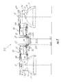
- FIG. 6 is a front plan view taken in FIG. 8 along the sight lines of the arrows designated 6 - 6 of an embodiment of components of an elevated platform for worker access to the tops of tanks carried by railcars with an emergency ladder and gate.
- FIG. 7 schematically presents a view taken in FIG. 3 along the sight lines of the arrows designated 7 - 7 of an embodiment of components of an elevated worker platform with track mounted, modular gangways and gates for worker access to the tops of tanks (shown in dashed line) carried by railcars.
- FIG. 8 is a top plan view similar to that taken in FIG. 3 of components of an embodiment of an elevated platform with modular side railings and gates for worker access to the tops of tanks (not shown) carried by railcars.
- FIG. 9 is a front plan view of an embodiment of components of an elevated platform with modular side railings and gates for worker access to the tops of tanks (not shown) carried by railcars.
- FIG. 10 is an isometric view of embodiments of components of an elevated platform for worker access to the tops of tanks carried by railcars with an emergency ladder and gate.
- ranges and limits mentioned herein include all sub-ranges located within the prescribed limits, inclusive of the limits themselves unless otherwise stated.
- a range from 100 to 200 also includes all possible sub-ranges, examples of which are from 100 to 150, 170 to 190, 153 to 162, 145.3 to 149.6, and 187 to 200.
- a limit of up to 7 also includes a limit of up to 5, up to 3, and up to 4.5, as well as all sub-ranges within the limit, such as from about 0 to 5, which includes 0 and includes 5 and from 5.2 to 7, which includes 5.2 and includes 7.
- the longitudinal direction extends along the length of a structure, and the length of an elongated structure is the longest dimension of the structure.
- the transverse direction extends perpendicular to the longitudinal direction along the width of a structure, and the width of an elongated structure is the shorter orthogonal dimension of the structure.
- the vertical direction typically is the orthogonal direction that is normal to both the transverse direction and the longitudinal direction and typically is parallel to the direction in which the force of gravity would tend to operate when the apparatus in question is being used for its intended purpose.
- one structure When one structure is selectively attached to another structure or selectively connected to another structure, it means that the two structures are attached or connected at the option of the user and thus can be separated from one another at the option of the user without damaging the two structures and without damaging the fastening elements that were used to effect the connection or attachment between the two structures.
- one structure when one structure is detachably attached to another structure or detachably connected to another structure, it means that the two structures are attached or connected at the option of the user and thus can be separated from one another at the option of the user without damaging the two structures and without damaging the fastening elements that were used to effect the connection or attachment between the two structures.
- the two structures can be reused repeatedly, and the fastening elements can be reused repeatedly as well.
- FIGS. 3 and 7 - 9 An embodiment of the apparatus 20 of present invention that includes an elevated platform 22 for worker access to the tops 13 a of tanks 13 carried by railcars in accordance with the present invention is depicted from different vantage points in each of FIGS. 3 and 7 - 9 for example. More detailed aspects of embodiments of various components of embodiments of the elevated platform 22 are shown in FIGS. 1 , 2 , 4 - 6 and 10 for example. As explained more fully below, because of the modular nature of some of these various components, different combinations of them can be made within the scope of the present invention so that one embodiment of one component may be combined with another embodiment of the same or a different component to yield a still further embodiment of the present invention.
- the apparatus 20 of the present invention may include an elevated platform, which is schematically represented by the element designated by the numeral 22 in FIG. 3 for example.
- the apparatus 20 desirably includes an elevated platform 22 that extends in a longitudinal direction and is defined in part by a deck 22 a .
- the deck 22 a of the elevated platform 22 typically is supported and suspended above the ground by a plurality of rigid legs 22 b that are the elongated, underlie the platform 22 and carry same.
- These rigid legs 22 b desirably may be formed from steel girders for example and are conventional in the art.
- inventions of the apparatus 20 of the present invention can be retrofitted to platforms 22 that already exist.
- the apparatus of the present invention permits non-destructive disassembly and detachable reassembly of these elements to the platform in order to accommodate repositioning of the swinging gates and the fixed railings in different arrangements and so permit worker access to different rail car configurations (especially regards the relative positioning of the loading hatches for the rail cars) as well as different rail train configurations (different rail cars connected successively in a different order in the train for example).
- the deck desirably has a pair of longitudinally extending sides that are separated apart from one another in the transverse direction, which is the direction that is normal to the virtual centerline 21 shown in dashed line in FIG. 8 for example.
- each side of the deck 22 a desirably is disposed to a respective opposite side of a virtual longitudinal centerline 21 that extends down the length of the platform 22 and is oriented normal to the transverse direction.
- the deck 22 a desirably is formed by steel decking that is rated to support the types of loads that are anticipated where the apparatus 20 will be installed.
- the apparatus 20 desirably includes a pair of longitudinally extending stringers 23 that form the opposite sides of the platform.
- a first stringer 23 is disposed along one side of the deck, and a second stringer 23 is disposed along the opposite side of the deck.
- FIGS. 1 and 2 illustrate an individual section of a modified metal I-bar that forms a section of an individual longitudinally extending stringer 23 .
- each stringer 23 defines an upper flange 23 a that extends along the length of the stringer 23 and extends generally in the transverse direction.
- each stringer 23 further defines a lower flange 23 b that is spaced vertically apart from the upper flange 23 a .
- the lower flange 23 b extends along the length of the first stringer 23 and also extends in the transverse direction.
- the upper flange 23 a of each stringer 23 defines a depending lip 23 c that extends along the length of the stringer 23 and extends generally in the vertical direction from the upper flange 23 a a short distance toward the lower flange 23 b to form one side of a three-sided channel 23 d .
- the upper and lower flanges 23 a , 23 b of each stringer 23 form part of a trackway 24 that includes the channel 23 d and extends along the length of each respective stringer 23 and thus extends longitudinally down each side of the deck 22 a.
- the apparatus 20 desirably includes at least a first gangway 30 , and desirably a plurality of gangways 30 such as shown in FIGS. 3 and 7 for example.
- each gangway 30 has an inboard end 30 a that is configured to be constrained within the trackway 24 of one of the stringers 23 .
- the inboard end 30 a of each gangway 30 is pivotally connected to the platform 22 and configured to slidably move along and generally within the trackway 24 of one of the stringers 23 .
- each gangway 30 also includes an outboard end 30 b that is spaced apart from and disposed generally opposite the inboard end 30 a in a transverse direction.
- a fall protection cage 35 can be provided and has an inboard end 35 a connected to the outboard end 30 b of the gangway 30 .
- each gangway 30 is configured for pivotal movement of the outboard end 30 b with respect to the inboard end 30 a .
- FIG. 4 illustrates the operational mode of the apparatus 20 in which the gangway 30 is completely retracted as the gangway 30 is slidably moving within the trackway 24 down the length thereof, such movement being in the direction into and out of the view shown in FIG. 4 for example.
- FIG. 7 illustrates the operational mode in which the apparatus 20 deploys a first gangway 30 from one side of the platform 22 and a second gangway 30 from the opposite side of the platform 22 in the fully extended mode so that each gangway 30 reaches the respective top 13 a of a tank 13 that is to be accessed by workers walking from the platform 22 onto the respective gangway 30 and onto the top 13 a of the respective tank 13 , which is shown in phantom by the chain dashed outline.
- each fall protection cage 35 is deployed over the work area on the top 13 a of the tank 13 .
- Also shown in chain dashed outline in FIG. 7 are the curved ladders 14 that provide access from each opposite side of the tank 13 , the safety railing 15 at the top of the ladders 14 carried by the tank 13 , and the service hatch 16 from which the cargo will be extracted from the tank 13 or loaded into the tank 13 , as the case may be.
- the width of the gangway 30 is defined between a first side 31 of the gangway 30 and a second side 32 of the gangway 30 opposing the first side 31 of the gangway 30 .
- the gangway 30 provides a walking surface 33 upon which workers can walk from the deck 22 a of the platform 22 onto the top 13 a of the tank 13 .
- FIGS. 3 and 7 The operative orientation of the gangways 30 is shown in FIGS. 3 and 7 for example.
- the walking surface 33 extends generally horizontally in a transverse direction from the platform 22 to the top 13 a of the tank 13 that is to be accessed by workers for inspection, loading or unloading.
- the gangway 30 and its walking surface 33 is pivoted above the platform 22 and disposed generally at a right angle with respect to the deck 22 a of the platform 22 .
- the walking surface 33 of the gangway 30 typically is bounded on each respective opposite side by a gangway railing that is indicated generally by the numeral 34 .
- the gangway railing 34 desirably is configured so that it can fold and collapse onto itself to permit the gangway 30 at the user's option to be raised above the normal horizontal walking plane and lowered to dispose the walking surface 33 of the gangway 30 in a position suited for workers to move between the top 13 a of the tank 13 and the deck 22 a of the platform 22 .
- each stringer 23 defines a plurality of bolt openings 25 .
- the spatial arrangement of the bolt openings 25 in each stringer 23 on each opposite side of the platform 22 desirably is the same, but can be different in some embodiments.
- these arrangements of bolt openings 25 can be done in pairs or triplets or any other multiple grouping instead of as a single bolt opening 25 , depending on the number of bolts needed to detachably anchor each of the modules of the platform railings and/or the gate modules 50 .
- groupings in pairs of bolt openings 25 will be used to explain this aspect of the present invention.
- each grouping of bolt openings 25 includes two side-by-side bolt openings 25 wherein each bolt opening 25 is defined vertically through the upper flange 23 a of the stringer 23 .
- the magnitude of the linear distance in the longitudinal direction between each pair of side-by-side bolt openings 25 of each grouping of bolt openings 25 is a gap that is generally designated by the upper case letter G.
- this gap G between the bolt openings 25 in each grouping of bolt openings 25 desirably will be the same throughout each such grouping of bolt openings 25 of the stringer 23 .
- a convenient reference point for measuring the distance that defines the gap G in the longitudinal direction between the pair of bolt openings 25 in a particular group of bolt openings 25 is the center of each bolt opening 25 .
- the reference point for the measures of the gap G is chosen as the point equidistant between the bolt openings 25 of each grouping or a different reference point doesn't matter so long as the chosen reference point remains consistent.
- a different number of bolt openings 25 in each grouping of bolt openings 25 is contemplated and could be for example three bolt openings 25 in each grouping or for example just a single bolt opening 25 in each grouping.
- no gap would exist and G becomes zero and thus would be inapplicable, and the meaning of the term grouping in such an instance would default to a set with only one member.
- each type of successive dual groupings of bolt openings 25 is characterized by a different standard separation distance measured in the longitudinal direction.
- one of the two types of successive dual groupings of bolt openings 25 defined in at least the upper flange 23 a of the first stringer 23 is characterized by a relatively smaller spacing measured in the longitudinal direction between any successive groupings of bolt openings 25 , and this relatively smaller spacing distance is denominated a first spacing and designated by the alphanumeric S 1 .
- this relatively smaller spacing distance is denominated a first spacing and designated by the alphanumeric S 1 .
- each of these smaller first spacings S 1 has the same magnitude.
- the other of the two types of successive dual groupings of bolt openings 25 defined in at least the upper flange 23 a of the first stringer 23 is characterized by a relatively larger spacing measured in the longitudinal direction between any the successive groupings of bolt openings 25 , and this relatively larger spacing distance is denominated a second spacing and designated by the alphanumeric S 2 .
- each of these larger second spacings S 2 has the same magnitude. It should be noted that if only a single bolt suffices to anchor the posts of the railing modules or gate modules 50 , then each grouping will be defined by a single bolt opening 25 that is separated by either the first spacing S 1 or the second spacing S 2 .
- the distance measured in the longitudinal direction between the end groupings of bolt openings 25 of two successive groupings of bolt openings 25 of the second type of successive dual groupings of bolt openings 25 characterized by the larger second spacing S 2 will have a magnitude that is a third spacing generally designated by the alphanumeric S 3 that is equal to two times (twice) the second spacing S 2 plus the first spacing S 1 , which is the separation distance between anchoring points of two side-by-side modules characterized by the unit spacing S 2 .
- 2 ⁇ S 2 +S 1 S 3 .
- the S 3 magnitude is equal to a whole number multiple (2 in the case of FIG. 1 ) of the S 2 magnitude plus the magnitude of the smaller spacing S 1 that exists between the two successive groupings of bolt openings 25 that are separated by the larger spacing magnitude S 2 .
- Conventional loading platforms include conventional side railings or fencing as well as swing gates that control worker access between the platform and the tops 13 a of the tanks 13 for purposes of loading or unloading.
- these conventional railings and swing gates are permanently welded to the conventional platform.
- the platform railings in accordance with the present invention are broken up into modules of one or more standard lengths, and these railing modules in accordance with the apparatus 20 of the present invention are selectively, detachably bolted to the stringers 23 that form part of the trackways 24 disposed along the sides of the deck 22 a of the platform 22 of the apparatus 21 of the present invention.
- each gate module 50 (described more fully hereafter) that includes a barrier 52 pivotally connected to a gate post 51 desirably is configured with a longitudinal dimension that permits a degree of interchangeability with embodiments of the modules of the platform railings 40 , 44 (described more fully hereafter).
- embodiments of the modules of the platform railings 40 , 44 are configured so that the longitudinal dimension of the largest module of the platform railings 40 is some whole number multiple of the longitudinal dimension of the smallest of the modules of platform railings 40 and/or the gate module 50 plus the separation distance S 1 between the anchoring points of the side-by-side smallest modules.
- any two side-by-side unit modules be they embodiments of platform railing modules 44 or embodiments of the gate modules 50 or one platform railing module 44 adjacent to an embodiment of one gate module 50 , can be interchanged with one of the larger platform railing modules 40 of the S 3 magnitude measured in the longitudinal dimension.
- this uniformity of the magnitudes of the spacings between the bolt openings 25 and the arrangement of the groupings of bolt openings 25 that permits a modular approach to the detachable attachment of the various fall protection components, which are described in more detail hereafter and that include for example the platform railing modules 40 , 44 and embodiments of the gate modules 50 .
- the apparatus 20 desirably includes at least a first platform railing module 40 that defines at least a first end post 41 and a second end post 42 that is spaced apart in the longitudinal direction from the first end post 41 .
- Each of the end posts 41 , 42 extends in a vertical direction and desirably can be connected by one or more horizontally elongated connecting rails 45 .
- Each end post 41 , 42 also has a vertically lower end that defines a foot flange 43 .
- Each foot flange 43 defines a grouping of bolt openings 26 , and these bolt openings 26 in the foot flange 43 are sized and spaced apart from one another in the same manner as each grouping of bolt openings 25 defined through the stringer 23 .
- the magnitude of the spacing in the longitudinal direction between the bolt openings 26 of each grouping of each foot flange 43 of each platform railing module 40 is the same first spacing G described above in relation each grouping of bolt openings 25 defined through the stringers 23 .
- the magnitude of the spacing in the longitudinal direction between the grouping of bolt openings 26 of the foot flange 43 of the first end post 41 and the grouping of bolt openings 26 of the foot flange 43 of the second end post 42 is a whole number multiple of the second spacing S 2 plus the first spacing S 1 .
- that whole number multiplier is the number 2.
- FIG. 1 that whole number multiplier is the number 2.
- the magnitude of the spacing in the longitudinal direction between the grouping of bolt openings 26 of the foot flange 43 of the first end post 41 and the grouping of the bolt openings 26 of the foot flange 43 of the second end post 42 desirably can be equal to the magnitude of the second spacing S 2 alone.
- pluralities of threaded bolts 27 and mating threaded nuts 28 are provided.
- a threaded bolt 27 is selectively received through one of the respective bolt openings 26 of the foot flange 43 of one of the end posts 41 or 42 as well as through an aligned bolt opening 25 of the upper flange 23 a of the stringer 23 so as to selectively attach that respective end post 41 or 42 of the platform railing module 40 or 44 via a respective threaded nut 28 that is tightened on the end of the respective threaded bolt 27 .
- a second threaded bolt 27 is selectively received through a respective bolt opening 26 of the foot flange 43 of the other end post 41 or 42 of the platform railing module 40 or 44 and successively through an aligned respective bolt opening 25 of the upper flange 23 a of the stringer 23 to selectively attach the opposite end post 41 or 42 of the platform railing module 40 or 44 via a second threaded nut 28 that is tightened on the end of the second threaded bolt 27 .
- each platform railing module 40 or 44 can be detachably connected to the platform 22 via the threaded nuts 28 attached to the threaded bolts 27 .
- each platform railing module 40 or 44 is easily achieved by undoing the bolts 27 and nuts 28 without damaging either the platform 22 , the platform railing module 40 or 44 or the bolts 27 and nuts 28 .
- use of the apparatus 20 of the present invention easily accommodates different rail car configurations and different train configurations pulled up alongside of the platform 22 for loading or unloading.
- the apparatus further desirably can include a plurality of swing gate modules 50 that are detachably connected to the platform 22 .
- each gate module 50 is detachably connected to the upper flange 23 a of the stringer 23 of the platform 22 .
- gate modules 50 desirably are configured and disposed so as to selectively control ingress and egress of workers between the deck 22 a and one of the gangways 30 .
- gate modules 50 also desirably are configured and disposed so as to selectively control ingress and egress of workers between the deck 22 a and one of the emergency egress ladders 17 (e.g., FIGS. 6 and 10 ).
- each gate module 50 desirably includes at least one gate post 51 and a gate barrier 52 that is pivotally connected to the gate post 51 .
- the pivotal connection between the barrier 52 and the gate post 51 desirably is effected by a spring-biased hinge connection 53 that biases the position of the barrier 52 in the closed position such as shown in FIGS. 1 and 2 for example.
- the gate module 50 desirably has its barrier 52 disposed so as to block passage of workers between the deck 22 a and a gangway 30 or an emergency egress ladder 17 (e.g., FIGS. 6 and 10 ).
- the gate module 50 desirably has its barrier 52 disposed in alignment with the adjacent platform railing module 40 or 44 .
- the barrier 52 of the gate module 50 desirably is provided with a stop flange 54 that prevents the spring-biased hinge connection 53 from moving the barrier past alignment with the adjacent platform railing module 40 or 44 .
- FIGS. 1 , 2 and 10 for example, the barrier 52 of the gate module 50 desirably is provided with a stop flange 54 that prevents the spring-biased hinge connection 53 from moving the barrier past alignment with the adjacent platform railing module 40 or 44 .
- each gate module 50 desirably is configured so that the spring-biased hinge connection 53 permits the worker to pivot the barrier 52 manually in a manner to swing the barrier 52 inwardly toward the longitudinal centerline 21 of the deck 22 a to open up worker passage between the deck 22 a and a gangway 30 or an emergency egress ladder 17 (e.g., FIGS. 6 and 10 ).
- the gate post 51 of each swing gate module 50 extends in a vertical direction and has a vertically lower end that defines a foot flange 55 .
- a single post serves as both the gate post 51 of the swing gate module 50 and an end post 42 of an adjacent platform railing module 44 , and thus the gate post 51 and the end 42 post share a foot flange 43 , 55 .
- the foot flange 43 , 55 defines a group of bolt openings 26 , 56 .
- the magnitude of the spacing in the longitudinal direction between the bolt openings 56 of the foot flange 55 of the gate post 51 is the same as the magnitude of the gap G in the foot flange 43 of the end posts 41 , 42 of the platform railing module 40 , 44 and thus the same as the gap G between the bolt openings 25 of the upper flange 23 a of the stringer 23 .
- the longitudinal extent of some embodiments of the gate module 50 desirably is one half of the longitudinal extent of one embodiment of the larger of the fixed railing modules 40 .
- the longitudinal dimension of some embodiments of the gate module 50 plus the longitudinal dimension of some embodiments of the smaller of the fixed railing modules 44 equals the longitudinal dimension of the larger of the fixed railing modules 40 .
- each gate module 50 configured so that when aligned in succession with one of the smaller of the fixed railing modules 44 , these two components of the apparatus 20 are be interchangeably detachably connected to upper flange of the stringer 23 with the larger of the fixed railing modules 40 .
- some embodiments of the gate modules 50 are configured so that when two of these embodiments of the gate modules 50 are aligned in succession they are interchangeably detachably connected to the upper flange 23 a of the stringer 23 with the larger of the fixed railing modules 40 .
- each such emergency egress ladder 17 includes a plurality of rungs 18 disposed horizontally between a pair of opposing side rails 19 and successively in a vertical direction downwardly from the platform 22 to permit workers to escape from the platform 22 in an emergency situation.
- the top rung 18 a of the emergency egress ladder 17 is disposed closest to the platform 22 among the plurality of rungs 18 .
- the top rung 18 a and the uppermost ends 19 a of the side rails 19 of the fixed emergency ladder 17 are disposed beneath the platform 22 so as not to interfere with the passage of the gangway 30 sliding along the trackway 24 up and down the length of the platform 22 . It is conventional therefore to provide a gate at the location of each of these fixed emergency egress ladders 17 , and this gate is biased in the closed position that blocks passage from the deck 22 a of the platform 22 to the top of the emergency ladder 17 .
- workers in order to descend the emergency ladder 17 , workers must open the gate disposed at the top of the ladder 17 and turn 180 degrees before stepping backwards with one foot to descend the ladder 17 .
- each worker who is rushing to descend the fixed emergency egress ladder 17 must take care in assuring that the worker's first step makes contact with the upper rung 18 a of the emergency ladder 17 .
- this first step must be taken in a direction that not only is descending from the platform 22 but also spaced apart in the transverse direction from the platform 22 , thereby increasing the chances of a misstep, especially during an emergency in which the workers are in a hurry to leave the deck 22 a of the platform 22 and descend the ladder 17 to reach the safety on the ground.
- each ladder extension module 60 is configured to be disposed in general alignment with the top of the emergency ladder 17 that extends vertically beneath the platform 22 .
- each ladder extension module 60 desirably is configured so as to be detachably connected to the platform 22 .
- each ladder extension module 60 is desirably configured so as to be detachably connected to the upper flange 23 a of the stringer 23 on one side of the deck 22 a .
- a ladder extension module 60 desirably can be retrofitted to a pre-installed swing gate that is disposed to provide access to a fixed emergency egress ladder 17 .
- the longitudinal dimension of one embodiment of a ladder extension module 60 desirably is the same as the longitudinal dimension of three of the smaller of the fixed railing modules 44 or the longitudinal dimension of three of one of embodiments of the gate modules 50 . Accordingly, one embodiment of a ladder extension module 60 is configured to be interchangeably detachably connected to the upper flange 23 a of the stringer 23 in place of two of the smaller of the fixed railing modules 44 and one of one embodiment of the gate modules 50 in succession.
- one embodiment of a ladder extension module 60 is configured to be interchangeably detachably connected to the upper flange 23 a of the stringer 23 in place of one of the larger of the fixed railing modules 40 and one of one embodiment of the gate modules 50 in succession.
- each ladder extension module 60 desirably includes a pair of sidebars 61 , 62 , and a first sidebar 61 is longitudinally spaced apart from a second sidebar 62 that is disposed generally in parallel with the first sidebar 61 . Furthermore, as shown in FIGS. 5 and 10 for example, each ladder extension module 60 desirably includes for each sidebar 61 , 62 , at least a first linkage 63 and desirably a plurality of linkages 63 . As shown in FIG. 10 for example, each ladder extension module 60 desirably includes for each sidebar 61 , 62 , at least a first linkage 63 and desirably a plurality of linkages 63 . As shown in FIG.
- each linkage 63 has one end pivotally connected to the sidebar 61 or 62 and a second end pivotally connected to the gate post 51 for the gate, whether it is the gate post 51 with the spring biased hinge or the gate post 41 of a railing module 40 or 44 that is disposed longitudinally spaced apart from the gate post 51 with the spring biased hinge 53 .
- the pivoting movement of the sidebars 61 with respect to the linkages 63 renders the ladder extension module 60 selectively deployable between an extended mode and a retracted mode.
- the retracted mode is indicated by the dashed outline
- the extended mode is indicated by the solid outline of the first sidebar 61 that is visible in the view of FIG. 5 .
- the sidebars 61 , 62 are disposed in a retracted position and folded against the gate post 51 or end post 41 or 42 (as the case may be) when the ladder extension module 60 is disposed in the retracted mode (dashed outline in FIG. 5 ).
- the respective sidebar 61 or 62 of the ladder extension module 60 is disposed spaced apart from the associated gate post 51 , 41 or 42 by a distance that is substantially comparable to the length of one of the respective linkages 63 .
- FIG. 5 for example, the sidebars 61 , 62 are disposed in a retracted position and folded against the gate post 51 or end post 41 or 42 (as the case may be) when the ladder extension module 60 is disposed in the retracted mode (dashed outline in FIG. 5 ).
- the respective sidebar 61 or 62 of the ladder extension module 60 is disposed spaced apart from the associated gate post 51 , 41 or 42 by a distance that is substantially comparable to the length of one of the respective linkages 63 .
- the ladder extension module 60 when the ladder extension module 60 is disposed in the retracted mode, the sidebars 61 , 62 are thus disposed in their retracted positions wherein each sidebar 61 , 62 rests against the respective connected gate post 51 or end post 41 or 42 .
- the ladder extension module 60 In the retracted mode schematically shown in FIG. 4 , the ladder extension module 60 is configured so as to permit the gangway 30 to bypass the ladder extension module 60 as the gangway 30 slides longitudinally along the trackway 24 .
- each ladder extension module 60 includes a ladder rung 64 that is connected between the pair of sidebars 61 , 62 , and accordingly this ladder rung 64 is selectively deployable between an extended mode and a retracted mode along with the sidebars 61 , 62 .
- the ladder rung 64 of each ladder extension module 60 is disposed close enough to the longitudinal centerline 21 of the deck 22 a so as to allow each gangway 30 to bypass the ladder rung 64 as the gangway 30 moves slidably along the trackway 24 .
- the sidebars 61 , 62 are disposed relatively farther away from the longitudinal centerline 21 of the deck 22 a .
- the sidebars 61 , 62 assume a disposition so that they are substantially vertically aligned with the upper ends 19 a of the fixed emergency ladder 17 .
- the ladder rung 64 of the ladder extension module 60 is likewise disposed in vertical alignment with the ladder rungs 18 a , 18 b of the fixed ladder 17 .
- the disposition of the ladder rung 64 in the ladder extension module 60 desirably is disposed so that the vertical distance between the top rung 18 a of the fixed ladder 17 and the rung 64 of the ladder extension module 60 is substantially the same as the vertical distance that separates at least the two uppermost rungs 18 a , 18 b of the fixed ladder 17 .
- the vertical distance separating the uppermost two rungs 18 a , 18 b of the emergency egress ladder 17 is deemed to be substantially the same as the vertical distance between the top rung 18 a of the emergency egress ladder 17 and the rung 64 of the ladder extension module 60 when the user of same is unlikely to notice any difference in vertical height during descent of the emergency ladder 17 via the ladder extension module 60 .
- the ladder extension module 60 assumes a configuration that acts as an uninterrupted extension of the fixed emergency ladder 17 , both as to the orientation of the sidebars 61 , 62 with the side rails 19 of the emergency ladder 17 and the orientation of the ladder extension's rung 64 with the rungs 18 of the emergency ladder 17 .
- the same platform railing modules 40 , 44 , and swinging gate modules 50 can be selectively detached and moved to different locations along the platform 22 and positioned in different arrangements with respect to one another.
- the same detachably interchangeable advantage is secured through use of the ladder extension module 60 in accordance with this aspect of the present invention.
Landscapes
- Engineering & Computer Science (AREA)
- Architecture (AREA)
- Mechanical Engineering (AREA)
- Civil Engineering (AREA)
- Structural Engineering (AREA)
- Refuge Islands, Traffic Blockers, Or Guard Fence (AREA)
- Bridges Or Land Bridges (AREA)
- Emergency Lowering Means (AREA)
Abstract
Description
Claims (16)
Priority Applications (3)
| Application Number | Priority Date | Filing Date | Title |
|---|---|---|---|
| US13/919,506 US9027712B2 (en) | 2013-06-17 | 2013-06-17 | Adaptable platform for loading and unloading railway cars |
| CA2851841A CA2851841C (en) | 2013-06-17 | 2014-05-13 | Adaptable platform for loading and unloading railway cars |
| US14/633,642 US9637975B2 (en) | 2013-06-17 | 2015-02-27 | Adaptable platform for loading and unloading railway cars |
Applications Claiming Priority (1)
| Application Number | Priority Date | Filing Date | Title |
|---|---|---|---|
| US13/919,506 US9027712B2 (en) | 2013-06-17 | 2013-06-17 | Adaptable platform for loading and unloading railway cars |
Related Child Applications (1)
| Application Number | Title | Priority Date | Filing Date |
|---|---|---|---|
| US14/633,642 Division US9637975B2 (en) | 2013-06-17 | 2015-02-27 | Adaptable platform for loading and unloading railway cars |
Publications (2)
| Publication Number | Publication Date |
|---|---|
| US20140367195A1 US20140367195A1 (en) | 2014-12-18 |
| US9027712B2 true US9027712B2 (en) | 2015-05-12 |
Family
ID=52018268
Family Applications (2)
| Application Number | Title | Priority Date | Filing Date |
|---|---|---|---|
| US13/919,506 Expired - Fee Related US9027712B2 (en) | 2013-06-17 | 2013-06-17 | Adaptable platform for loading and unloading railway cars |
| US14/633,642 Active 2033-09-09 US9637975B2 (en) | 2013-06-17 | 2015-02-27 | Adaptable platform for loading and unloading railway cars |
Family Applications After (1)
| Application Number | Title | Priority Date | Filing Date |
|---|---|---|---|
| US14/633,642 Active 2033-09-09 US9637975B2 (en) | 2013-06-17 | 2015-02-27 | Adaptable platform for loading and unloading railway cars |
Country Status (2)
| Country | Link |
|---|---|
| US (2) | US9027712B2 (en) |
| CA (1) | CA2851841C (en) |
Cited By (8)
| Publication number | Priority date | Publication date | Assignee | Title |
|---|---|---|---|---|
| US10087641B2 (en) | 2015-10-07 | 2018-10-02 | Safe Rack Llc | Cage assembly for use with pivotal gangway |
| US10760235B1 (en) * | 2019-07-18 | 2020-09-01 | Todd Edmondson Klingback | Frac stand safety work platform |
| US20210047846A1 (en) * | 2018-04-20 | 2021-02-18 | Deltak Manufacturing, Inc. | Scaffold Gate Toeboard Assembly for Use on a Scaffold Gate |
| US20210156152A1 (en) * | 2019-11-22 | 2021-05-27 | The Boeing Company | Telescoping Guardrail/Flip Door |
| US20220230902A1 (en) * | 2021-01-20 | 2022-07-21 | Asm Ip Holding B.V. | Fall prevention devices and methods |
| US20220306224A1 (en) * | 2021-03-25 | 2022-09-29 | Safesmart Llc | Trailer Safety Rail |
| US20230011346A1 (en) * | 2021-07-07 | 2023-01-12 | The Boeing Company | Systems and Methods for Preventing a Walkway Platform Flip Door From Being Raised Without a Guardrail Installed |
| US20230010425A1 (en) * | 2021-07-07 | 2023-01-12 | The Boeing Company | Inboard-Mounted Safety Latch Mechanism for Preventing a Walkway Platform Flip Door From Being Raised Without a Guardrail Installed |
Families Citing this family (14)
| Publication number | Priority date | Publication date | Assignee | Title |
|---|---|---|---|---|
| US9169693B2 (en) * | 2009-09-18 | 2015-10-27 | Safe Rack Llc | Mobile access unit and cage |
| US10072465B1 (en) * | 2013-03-15 | 2018-09-11 | Integris Rentals, L.L.C. | Containment work platform |
| US9598250B1 (en) * | 2014-04-09 | 2017-03-21 | Sam Carbis Asset Management, Llc | Fall protection unit for forklift trucks servicing flatbed trailers |
| DE102014013898A1 (en) * | 2014-09-18 | 2016-03-24 | Rosenbauer International Ag | Rescue basket, as well as equipped Hubrettungsfahrzeug |
| US20150246641A1 (en) * | 2015-04-29 | 2015-09-03 | Caterpillar Inc. | Guardrail system for a cab environment of a mobile machine |
| JP6646986B2 (en) * | 2015-09-11 | 2020-02-14 | 中電プラント株式会社 | Lifting fence |
| US10724256B1 (en) * | 2017-05-04 | 2020-07-28 | Sam Carbis Asset Management, Llc. | Enhanced safety cage apparatus for work areas on top of rolling stock such as rail tank cars |
| US11142951B2 (en) * | 2018-11-16 | 2021-10-12 | Lorad, LLC | Ladder standoff and ladder incorporating the standoff |
| US11885142B2 (en) * | 2019-04-26 | 2024-01-30 | WIFCO Steel Products, Inc. | Stair and walkway system and method |
| CN110577095B (en) * | 2019-08-29 | 2024-04-19 | 天津市峤通物流有限公司 | Railway wheel type movable automatic loading and unloading platform system |
| CN110758458B (en) * | 2019-09-19 | 2024-10-01 | 中铁第四勘察设计院集团有限公司 | Common-column common-length type power-centralized motor train unit three-dimensional maintenance operation platform with existing structure |
| CN112456056A (en) * | 2020-12-06 | 2021-03-09 | 广州通发智能装备股份有限公司 | Material transmission platform |
| US20230407650A1 (en) * | 2022-06-15 | 2023-12-21 | Richard Martinez | Scaffolding System |
| CN116394996B (en) * | 2023-04-11 | 2023-12-05 | 捷航设备制造股份有限公司 | Electric putter control three-layer platform panel turnover mechanism |
Citations (19)
| Publication number | Priority date | Publication date | Assignee | Title |
|---|---|---|---|---|
| US4679657A (en) * | 1986-01-23 | 1987-07-14 | Aluminum Ladder Company | Mobile tank vehicle access system |
| US5042612A (en) * | 1990-06-15 | 1991-08-27 | Aluminum Ladder Company | Bulk material load vehicle access system |
| US6502267B2 (en) | 2001-05-16 | 2003-01-07 | Aluminum Ladder Company | Conveyor crossover |
| US7140467B2 (en) | 2004-04-29 | 2006-11-28 | Aluminum Ladder Co | Bulk material transport vehicle access structure |
| US7216741B2 (en) * | 2004-08-30 | 2007-05-15 | Aluminum Ladder Company | Safety cage for gangway |
| US7832525B2 (en) * | 2005-12-05 | 2010-11-16 | Aluminum Ladder Company | Access platform for flatbeds |
| US7950095B2 (en) | 2007-12-09 | 2011-05-31 | Safe Rack Llc | Gangway and method for manufacturing same |
| US8015647B2 (en) * | 2009-10-06 | 2011-09-13 | Aluminum Ladder Company | Extended safety cage for retractable gangway |
| US8051951B2 (en) * | 2009-06-04 | 2011-11-08 | Aluminum Ladder Company | Retractable access platform |
| US20120006619A1 (en) * | 2010-07-07 | 2012-01-12 | Aluminum Ladder Company | Cement industry gangway |
| US20120042458A1 (en) * | 2010-08-20 | 2012-02-23 | Aluminum Ladder Company | Pivot block connection |
| US20120045274A1 (en) * | 2010-08-20 | 2012-02-23 | Aluminum Ladder Company | Automatic locking device for track mounted gangway |
| US20120048648A1 (en) * | 2010-08-25 | 2012-03-01 | Aluminum Ladder Company | Pivoting handrail system |
| US8261393B2 (en) | 2008-08-10 | 2012-09-11 | Saferack, Llc | Fall restraint equipment component and method for manufacturing the same |
| US20130015016A1 (en) * | 2011-07-16 | 2013-01-17 | Safe Rack Llc | Platform system |
| US8387191B2 (en) * | 2010-07-22 | 2013-03-05 | Safe Rack Llc | Gangway bearing retainer plate |
| US8403109B2 (en) * | 2009-12-02 | 2013-03-26 | Aluminum Ladder Company | Tracking gate for extended gangway |
| US20130219790A1 (en) | 2012-02-15 | 2013-08-29 | Safe Rack, Llc | Gate |
| US8561239B2 (en) | 2010-08-17 | 2013-10-22 | Safe Rack Llc | Articulating cage |
Family Cites Families (12)
| Publication number | Priority date | Publication date | Assignee | Title |
|---|---|---|---|---|
| US304821A (en) * | 1884-09-09 | hofele | ||
| US279347A (en) * | 1883-06-12 | bubns | ||
| US743199A (en) * | 1903-05-02 | 1903-11-03 | Franz Scherrer | Ladder for life-saving. |
| US887550A (en) * | 1906-12-04 | 1908-05-12 | Jacobus Johannes Van Broekhoven | Fire-escape. |
| US2794583A (en) * | 1952-08-02 | 1957-06-04 | Ohio Commw Eng Co | Press ladder construction |
| US3117651A (en) * | 1961-11-17 | 1964-01-14 | Lum A Scape Products Inc | Fire escape system |
| US3601220A (en) * | 1970-01-05 | 1971-08-24 | Richard Saucier | Retractable ladder |
| US3856109A (en) * | 1973-09-07 | 1974-12-24 | R Gates | Ladder device |
| US4401183A (en) * | 1982-04-02 | 1983-08-30 | Eli Schler | High rise life escape ladders |
| US6095283A (en) * | 1999-02-26 | 2000-08-01 | Ellis; J. Nigel | Walk-through ladder |
| AUPS040402A0 (en) * | 2002-02-08 | 2002-03-07 | Hedweld Engineering Pty Ltd | Foldable access device |
| US9663989B2 (en) * | 2012-01-23 | 2017-05-30 | Wing Enterprises, Inc. | Elevated working platform and related methods |
-
2013
- 2013-06-17 US US13/919,506 patent/US9027712B2/en not_active Expired - Fee Related
-
2014
- 2014-05-13 CA CA2851841A patent/CA2851841C/en active Active
-
2015
- 2015-02-27 US US14/633,642 patent/US9637975B2/en active Active
Patent Citations (23)
| Publication number | Priority date | Publication date | Assignee | Title |
|---|---|---|---|---|
| US4679657A (en) * | 1986-01-23 | 1987-07-14 | Aluminum Ladder Company | Mobile tank vehicle access system |
| US5042612A (en) * | 1990-06-15 | 1991-08-27 | Aluminum Ladder Company | Bulk material load vehicle access system |
| US5392878A (en) | 1990-06-15 | 1995-02-28 | Aluminum Ladder Company | Bulk material load vehicle access system |
| US6502267B2 (en) | 2001-05-16 | 2003-01-07 | Aluminum Ladder Company | Conveyor crossover |
| US7140467B2 (en) | 2004-04-29 | 2006-11-28 | Aluminum Ladder Co | Bulk material transport vehicle access structure |
| US7216741B2 (en) * | 2004-08-30 | 2007-05-15 | Aluminum Ladder Company | Safety cage for gangway |
| US7832525B2 (en) * | 2005-12-05 | 2010-11-16 | Aluminum Ladder Company | Access platform for flatbeds |
| US7950095B2 (en) | 2007-12-09 | 2011-05-31 | Safe Rack Llc | Gangway and method for manufacturing same |
| US8341821B2 (en) | 2008-08-10 | 2013-01-01 | Saferack, Llc | Fall restraint equipment components and method for manufacturing the same |
| US8261393B2 (en) | 2008-08-10 | 2012-09-11 | Saferack, Llc | Fall restraint equipment component and method for manufacturing the same |
| US8051951B2 (en) * | 2009-06-04 | 2011-11-08 | Aluminum Ladder Company | Retractable access platform |
| US8015647B2 (en) * | 2009-10-06 | 2011-09-13 | Aluminum Ladder Company | Extended safety cage for retractable gangway |
| US8403109B2 (en) * | 2009-12-02 | 2013-03-26 | Aluminum Ladder Company | Tracking gate for extended gangway |
| US20120006619A1 (en) * | 2010-07-07 | 2012-01-12 | Aluminum Ladder Company | Cement industry gangway |
| US8479882B2 (en) | 2010-07-07 | 2013-07-09 | Aluminum Ladder Company | Cement industry gangway |
| US8387191B2 (en) * | 2010-07-22 | 2013-03-05 | Safe Rack Llc | Gangway bearing retainer plate |
| US8561239B2 (en) | 2010-08-17 | 2013-10-22 | Safe Rack Llc | Articulating cage |
| US20120045274A1 (en) * | 2010-08-20 | 2012-02-23 | Aluminum Ladder Company | Automatic locking device for track mounted gangway |
| US20120042458A1 (en) * | 2010-08-20 | 2012-02-23 | Aluminum Ladder Company | Pivot block connection |
| US8479884B2 (en) | 2010-08-20 | 2013-07-09 | Aluminum Ladder Company | Automatic locking device for track mounted gangway |
| US20120048648A1 (en) * | 2010-08-25 | 2012-03-01 | Aluminum Ladder Company | Pivoting handrail system |
| US20130015016A1 (en) * | 2011-07-16 | 2013-01-17 | Safe Rack Llc | Platform system |
| US20130219790A1 (en) | 2012-02-15 | 2013-08-29 | Safe Rack, Llc | Gate |
Cited By (16)
| Publication number | Priority date | Publication date | Assignee | Title |
|---|---|---|---|---|
| US10087641B2 (en) | 2015-10-07 | 2018-10-02 | Safe Rack Llc | Cage assembly for use with pivotal gangway |
| US10822818B2 (en) | 2015-10-07 | 2020-11-03 | Safe Rack Llc | Cage assembly for use with pivotal gangway |
| US20210040750A1 (en) * | 2015-10-07 | 2021-02-11 | Safe Rack Llc | Cage assembly for use with pivotal gangway |
| US20210047846A1 (en) * | 2018-04-20 | 2021-02-18 | Deltak Manufacturing, Inc. | Scaffold Gate Toeboard Assembly for Use on a Scaffold Gate |
| US11761217B2 (en) * | 2018-04-20 | 2023-09-19 | Deltak Manufacturing, Inc. | Scaffold gate toeboard assembly for use on a scaffold gate |
| US10760235B1 (en) * | 2019-07-18 | 2020-09-01 | Todd Edmondson Klingback | Frac stand safety work platform |
| US11512477B2 (en) * | 2019-11-22 | 2022-11-29 | The Boeing Company | Telescoping guardrail/flip door |
| US20210156152A1 (en) * | 2019-11-22 | 2021-05-27 | The Boeing Company | Telescoping Guardrail/Flip Door |
| US20220230902A1 (en) * | 2021-01-20 | 2022-07-21 | Asm Ip Holding B.V. | Fall prevention devices and methods |
| US12404120B2 (en) * | 2021-01-20 | 2025-09-02 | Asm Ip Holding B.V. | Fall prevention devices and methods |
| US20220306224A1 (en) * | 2021-03-25 | 2022-09-29 | Safesmart Llc | Trailer Safety Rail |
| US12227244B2 (en) * | 2021-03-25 | 2025-02-18 | Safesmart Llc | Safety rail |
| US20230011346A1 (en) * | 2021-07-07 | 2023-01-12 | The Boeing Company | Systems and Methods for Preventing a Walkway Platform Flip Door From Being Raised Without a Guardrail Installed |
| US20230010425A1 (en) * | 2021-07-07 | 2023-01-12 | The Boeing Company | Inboard-Mounted Safety Latch Mechanism for Preventing a Walkway Platform Flip Door From Being Raised Without a Guardrail Installed |
| US12404707B2 (en) * | 2021-07-07 | 2025-09-02 | The Boeing Company | Systems and methods for preventing a walkway platform flip door from being raised without a guardrail installed |
| US12421741B2 (en) * | 2021-07-07 | 2025-09-23 | The Boeing Company | Inboard-mounted safety latch mechanism for preventing a walkway platform flip door from being raised without a guardrail installed |
Also Published As
| Publication number | Publication date |
|---|---|
| US9637975B2 (en) | 2017-05-02 |
| CA2851841A1 (en) | 2014-12-17 |
| CA2851841C (en) | 2017-06-13 |
| US20150167327A1 (en) | 2015-06-18 |
| US20140367195A1 (en) | 2014-12-18 |
Similar Documents
| Publication | Publication Date | Title |
|---|---|---|
| US9027712B2 (en) | Adaptable platform for loading and unloading railway cars | |
| US8051951B2 (en) | Retractable access platform | |
| US8479882B2 (en) | Cement industry gangway | |
| US8015647B2 (en) | Extended safety cage for retractable gangway | |
| US11649648B2 (en) | Enhanced safety cage apparatus for work areas on top of rolling stock such as rail tank cars | |
| JP6609342B2 (en) | Hallway for boarding and exiting aircraft | |
| US7216741B2 (en) | Safety cage for gangway | |
| US5921531A (en) | Retractable handrail for railroad cars | |
| US8555444B2 (en) | Joint equipment and boarding bridge having the same | |
| US20150298613A1 (en) | Safety railing system and method for providing access to a tanker trailer | |
| US20120006618A1 (en) | Cement industry gangway and safety cage | |
| US3524207A (en) | Over-the-wing access structure for servicing multiple doors in commercial jet aircraft | |
| CA2944316C (en) | Cage assembly for use with pivotal gangway | |
| CA2969994A1 (en) | Railcar safety appliances | |
| US8816877B2 (en) | Road gantry | |
| RU208450U1 (en) | The platform for the exit to the roof of the train is mobile | |
| CA2935975C (en) | Autorack railroad car having convertible deck structure | |
| WO2019041611A1 (en) | Combined board-side suspension ladder device | |
| US9550079B2 (en) | Multilevel railcar safety catch system | |
| ES2302476B1 (en) | PASSENGER OF BOARDING AND UNLOADING FOR VESSELS. | |
| CN113247033A (en) | Foldable guardrail and railway wagon | |
| CN2871723Y (en) | Ship maintenance equipment | |
| CN219057483U (en) | Conveyor pedestrian crossing improved device | |
| RU148489U1 (en) | LOADING AND UNLOADING BOARD | |
| CN111648223A (en) | Retractable strides over ladder |
Legal Events
| Date | Code | Title | Description |
|---|---|---|---|
| AS | Assignment |
Owner name: ALUMINUM LADDER COMPANY, A SOUTH CAROLINA CORPORAT Free format text: ASSIGNMENT OF ASSIGNORS INTEREST;ASSIGNORS:MELTON, ALLAN J.;THOMASSON, ALLYN;WILLIAMSON, RODRICK;REEL/FRAME:030644/0255 Effective date: 20130618 |
|
| AS | Assignment |
Owner name: CARBIS HOLDINGS, INC., SOUTH CAROLINA Free format text: MERGER;ASSIGNOR:ALUMINUM LADDER COMPANY;REEL/FRAME:032174/0570 Effective date: 20131230 |
|
| AS | Assignment |
Owner name: SAM CARBIS ASSET MANAGEMENT, LLC, SOUTH CAROLINA Free format text: ASSIGNMENT OF ASSIGNORS INTEREST;ASSIGNOR:CARBIS HOLDINGS, INC.;REEL/FRAME:032788/0856 Effective date: 20140430 |
|
| STCF | Information on status: patent grant |
Free format text: PATENTED CASE |
|
| MAFP | Maintenance fee payment |
Free format text: PAYMENT OF MAINTENANCE FEE, 4TH YR, SMALL ENTITY (ORIGINAL EVENT CODE: M2551); ENTITY STATUS OF PATENT OWNER: SMALL ENTITY Year of fee payment: 4 |
|
| FEPP | Fee payment procedure |
Free format text: MAINTENANCE FEE REMINDER MAILED (ORIGINAL EVENT CODE: REM.); ENTITY STATUS OF PATENT OWNER: SMALL ENTITY |
|
| LAPS | Lapse for failure to pay maintenance fees |
Free format text: PATENT EXPIRED FOR FAILURE TO PAY MAINTENANCE FEES (ORIGINAL EVENT CODE: EXP.); ENTITY STATUS OF PATENT OWNER: SMALL ENTITY |
|
| STCH | Information on status: patent discontinuation |
Free format text: PATENT EXPIRED DUE TO NONPAYMENT OF MAINTENANCE FEES UNDER 37 CFR 1.362 |
|
| FP | Lapsed due to failure to pay maintenance fee |
Effective date: 20230512 |