US9024218B2 - Control device comprising a movable upper panel for actuating a switching breaker - Google Patents
Control device comprising a movable upper panel for actuating a switching breaker Download PDFInfo
- Publication number
- US9024218B2 US9024218B2 US13/857,498 US201313857498A US9024218B2 US 9024218 B2 US9024218 B2 US 9024218B2 US 201313857498 A US201313857498 A US 201313857498A US 9024218 B2 US9024218 B2 US 9024218B2
- Authority
- US
- United States
- Prior art keywords
- upper panel
- armature
- breaker
- switching breaker
- contact point
- Prior art date
- Legal status (The legal status is an assumption and is not a legal conclusion. Google has not performed a legal analysis and makes no representation as to the accuracy of the status listed.)
- Active, expires
Links
Images


Classifications
-
- H—ELECTRICITY
- H01—ELECTRIC ELEMENTS
- H01H—ELECTRIC SWITCHES; RELAYS; SELECTORS; EMERGENCY PROTECTIVE DEVICES
- H01H3/00—Mechanisms for operating contacts
- H01H3/02—Operating parts, i.e. for operating driving mechanism by a mechanical force external to the switch
- H01H3/12—Push-buttons
- H01H3/122—Push-buttons with enlarged actuating area, e.g. of the elongated bar-type; Stabilising means therefor
-
- G—PHYSICS
- G06—COMPUTING OR CALCULATING; COUNTING
- G06F—ELECTRIC DIGITAL DATA PROCESSING
- G06F3/00—Input arrangements for transferring data to be processed into a form capable of being handled by the computer; Output arrangements for transferring data from processing unit to output unit, e.g. interface arrangements
- G06F3/01—Input arrangements or combined input and output arrangements for interaction between user and computer
- G06F3/03—Arrangements for converting the position or the displacement of a member into a coded form
- G06F3/033—Pointing devices displaced or positioned by the user, e.g. mice, trackballs, pens or joysticks; Accessories therefor
- G06F3/0354—Pointing devices displaced or positioned by the user, e.g. mice, trackballs, pens or joysticks; Accessories therefor with detection of two-dimensional [2D] relative movements between the device, or an operating part thereof, and a plane or surface, e.g. 2D mice, trackballs, pens or pucks
- G06F3/03547—Touch pads, in which fingers can move on a surface
-
- G—PHYSICS
- G06—COMPUTING OR CALCULATING; COUNTING
- G06F—ELECTRIC DIGITAL DATA PROCESSING
- G06F3/00—Input arrangements for transferring data to be processed into a form capable of being handled by the computer; Output arrangements for transferring data from processing unit to output unit, e.g. interface arrangements
- G06F3/01—Input arrangements or combined input and output arrangements for interaction between user and computer
- G06F3/03—Arrangements for converting the position or the displacement of a member into a coded form
- G06F3/041—Digitisers, e.g. for touch screens or touch pads, characterised by the transducing means
- G06F3/0414—Digitisers, e.g. for touch screens or touch pads, characterised by the transducing means using force sensing means to determine a position
Definitions
- the present disclosure relates to a device for the control of an electronic apparatus, the device including a movable upper panel on which at least one control action is exerted.
- the present disclosure relates particularly to a device for the control of an electronic apparatus
- the device includes an upper panel which extends in a globally horizontal plane, comprising an upper, so-called actuation, face on which, by means of a control member, a user can exert at least one control action by applying to this upper face a globally downward oriented pressure loading; a lower support armature with respect to which the upper panel, under the effect of the control action, that is movably mounted according to a vertical motion between a top rest position, to which the panel is elastically restored, and an active bottom position; a switching breaker which is triggered directly by the upper panel to produce a control signal for the electronic apparatus when the upper panel is in its active bottom position; and an articulated structure which is interposed vertically between the upper panel and the armature to hold the upper panel globally parallel to itself in a horizontal plane during its downward vertical motion with respect to the armature.
- Such a control device is made in such a way that, under the effect of the control action, the upper panel is able to move downwards, according to a motion consisting globally of a vertical translation, so as to act on the switching breaker with a view to causing its triggering, that is to say with a view to causing a change of switching state by for example toggling the electrical breaker from a rest state in which it is normally open, to a closed active state.
- the articulated structure cooperates with the upper panel and with the lower armature to suspend and hold the upper panel substantially parallel to its horizontal plane when a control action able to cause its vertical displacement is exerted.
- Such a device exhibits a global imbalance of the upper panel “about” the vertical axis of the switch which causes unchecked tilting motions of the upper panel, in particular as a function of the position, in the upper actuation face, of the point at which the control action is applied.
- this design causes an imbalance of the system depending on whether the control action is exerted on the upper panel at a point positioned in proximity to the position of the switching breaker, or at a point distant from the latter.
- These imbalances associated with the interactions of the pantograph with the upper panel, induce in particular a non-regularity of the manipulation sensations for the user.
- the resulting force of the control action is not transmitted in a homogeneous manner to the switching breaker.
- One aim of the present disclosure is in particular to propose a device for the control of an electronic apparatus making it possible to hold the upper panel parallel to its horizontal plane whatever the position of the point of application of the control action.
- the present disclosure proposes a device for the control of an electronic apparatus of the type mentioned above, wherein the vertical axis of actuation of the switching breaker, which is carried by the lower armature or by the upper panel, is arranged at the periphery of the contour of the upper panel; and the articulated structure comprises several consecutive shafts, for transmission of loadings and of motions towards the breaker.
- Each shaft may extend in a rectilinear direction and is arranged along an associated edge of the contour of the upper actuation face; comprise a first distal (with respect to the switching breaker) end segment which bears vertically downwards against a distal contact point belonging to the lower armature, and which bears vertically upwards against a distal contact point belonging to the upper panel; and comprise a second proximal (with respect to the switching breaker) end segment which bears vertically upwards against a proximal contact point belonging to the lower armature, and which bears vertically downwards against a proximal contact point belonging to the upper panel.
- each shaft its two points of contact, distal and proximal, with the upper panel may be arranged longitudinally according to a first longitudinal geometric axis, and its two points of contact, distal and proximal, with the lower armature may be arranged longitudinally according to a second geometric axis which is parallel to the first geometric axis.
- the vertical axis of actuation of the switching breaker may be arranged between the two proximal end segments of two consecutive shafts; the switching breaker may be interposed vertically between the upper panel and the lower armature, the switching breaker configured to produce a control signal when it is subjected to a pressure loading greater than a predetermined threshold value, and when the value of the pressure loading is less than the said threshold value, the switching breaker constitutes an abutment of the upper panel in its upper rest position to which it is restored elastically by the switching breaker; by virtue of which, the switching breaker makes it possible to detect any control action consisting in exerting on the upper face of the upper panel a pressure greater than a so-called predetermined threshold value.
- each shaft may be rotatably mounted with respect to the upper panel about a geometric axis globally parallel to the rectilinear direction along which it extends between its two end segments, distal and proximal; and may be rotatably mounted with respect to the lower armature, about an axis globally parallel to the rectilinear direction along which it extends between its two distal end segments, by virtue of which the relative motions of the upper panel with respect to the lower armature transmitted to the distal end segment are transmitted and applied to the proximal end segment in the form of a couple.
- each shaft may comprises a rectilinear central part, a rectilinear distal end part parallel to the central part and offset laterally with respect to the central part, and a proximal end part which is aligned longitudinally with the proximal end part, the said two contact points belonging to the upper panel cooperate with opposite zones of the said central part, and each contact point belonging to the lower armature cooperates with an opposite zone of the associated end part.
- the upper actuation face may be delimited by a polygonal contour, in particular a rectangle, and at least two consecutive shafts are arranged along at least two consecutive sides of the polygonal contour, respectively.
- the device may exhibit a general symmetry of design with respect to a vertical plane of symmetry passing through the vertical axis of actuation of the switching breaker.
- Each shaft may be associated with at least one adjusting member which is associated in an adjustable manner, in the vertical direction, with the lower armature in order to take up all of the assembly plays and apply a preload to the associated shaft.
- FIG. 1 depicts a schematic perspective representation of a first exemplary embodiment of a control device according to the invention.
- FIG. 2 depicts an exploded perspective view of the control device represented in FIG. 1 .
- FIG. 3 depicts a perspective view, according to another angle of view, of certain of the components represented in FIG. 2 .
- FIG. 4 depicts a larger-scale view of certain of the components of the device represented in FIG. 1 .
- FIG. 5 depicts a view analogous to that of FIG. 4 illustrating certain components of the device of FIG. 1 .
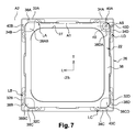
- FIG. 6 depicts a view from below of the device of FIG. 1 .
- FIG. 7 depicts a view analogous to that of FIG. 6 illustrating certain of the components of the device.
- FIGS. 9 to 12 depict large-scale detail views illustrating, successively in the four corner angles, components of the device such as they are arranged in FIG. 4 .
- FIG. 16 depicts a schematic representation of the main components of the device of FIG. 1 with a view to explaining the operation thereof.
- FIG. 17 depicts a diagram making it possible to illustrate the operation of a shaft of the device according to the invention.
- FIG. 18 depicts a developed schematic view of the device represented in FIG. 1 making it possible to explain the operation thereof.
- FIGS. 19 and 20 depict schematic views illustrating the design principle of two variants of the principle of the invention implemented in the device illustrated in FIGS. 1 and 16 respectively.
- FIG. 21 depicts a view analogous to that of FIG. 2 of a second exemplary embodiment of a control device according to the invention corresponding to the variant shown diagrammatically in FIG. 19 .
- FIG. 23 depicts a view analogous to that of FIG. 15 which illustrates two consecutive shafts of the device represented in FIG. 21 .
- FIG. 25 depicts a view from below of certain of the components of the device illustrated in FIGS. 21 and 22 .
- FIG. 28 depicts a view from below of the components illustrated in FIGS. 21 and 22 shown in the assembled position.
- FIGS. 29 to 31 depict larger-scale perspective views illustrating the cooperation of the shafts with the lower armature and/or the upper panel.
- a device 20 for the control of an electronic apparatus such as for example a computer, a portable digital apparatus, often called by its English initials PDA for “Personal Digital Assistant”, or else a “Smartphone”, combining the characteristics of a PDA and those of a digital telephone, or else a remote control for remotely controlling various electronic apparatuses such as for example audiovisual apparatuses, air-conditioning apparatuses, etc.
- an electronic apparatus such as for example a computer, a portable digital apparatus, often called by its English initials PDA for “Personal Digital Assistant”, or else a “Smartphone”, combining the characteristics of a PDA and those of a digital telephone, or else a remote control for remotely controlling various electronic apparatuses such as for example audiovisual apparatuses, air-conditioning apparatuses, etc.
- the control device may comprise an upper panel 21 on which a user acts for the control of the electronic apparatus.
- the upper panel 21 may comprise a plane element which is of horizontal orientation and of square or rectangular shape, whose sides are parallel to the longitudinal L and transverse T directions.
- the upper panel 21 may be constructed here, by way of nonlimiting example, of two pieces comprising a peripheral frame 22 and an “active” central block 23 which, in the assembled position of these two components, form an integral whole 21 .
- the central block 23 may solely include a plate, of, for example, rigid plastic, so as to constitute a simple control “button”.
- the central block 23 is “active” and may comprise means for locating the position of the contact point on the upper face 23 s .
- the control device 20 is then of the type called a “Touch Pad”, used for example for a laptop computer.
- the block 23 of the upper panel 21 may comprise information display means, for example a display screen, to allow the user to see information relating to the electronic apparatus, and/or information associated with the manipulations that the user performs on the upper panel 21 .
- the upper panel 21 is then a component commonly called a “Touchscreen”.
- the control device 20 may be, for example, intended to be mounted in an electronic apparatus in such a way that the upper face 23 s of the block 23 of the upper panel 21 is flush with a casing or cladding element of the electronic apparatus.
- the control device 20 may also comprise a lower armature 26 , by way of which the control device 20 is assembled and fixed inside the electronic apparatus.
- the lower armature 26 is represented in the figures in the form of a square frame which, in the assembled position of the main components of the control device 20 , may surround the peripheral frame 22 of the upper panel 21 in such a way that, as may be seen in particular in FIG. 1 , the three components 22 , 23 and 26 may extend in the same horizontal plane so as to form a control device 20 of generally plane shape and of reduced height corresponding for example to the vertical thickness of the armature 26 .
- the armature 26 may be, for example, fixed on a printed circuit board “PCB” of the electronic apparatus and the whole of the central part inside the armature 26 situated under the upper panel 21 is cleared for the arranging of electronic or electrical components and corresponding circuits on the upper face of the printed circuit board.
- PCB printed circuit board
- the control device 20 may further comprise an articulated structure which is interposed, globally vertically, between the frame 22 of the upper panel 21 and the lower armature 26 to hold the upper panel 21 parallel to the horizontal plane, that is to say parallel to itself, during the vertical motions of the upper panel 21 with respect to the armature 26 , and in particular during any downward vertical motion of the upper panel 21 .
- the articulated structure here may be composed of four consecutive peripheral shafts for transmitting loadings and motions LA, LB, LC and LD. Each shaft may extend in a globally rectilinear direction and it is arranged along an associated edge of the contour 27 of the upper face 23 s for actuating the control device 20 .
- each “side” of the control device 20 may thus be associated with a letter with index A, B, C, or D, and each of the angles or corners of the device is associated with a pair of letters with index A and B, B and C, C and D or D and A respectively.
- the control device may comprise, arranged at its corner AD, a switching breaker S and each shaft may thus comprise, by definition, a proximal longitudinal end situated closest to the switching breaker S, and a distal longitudinal end situated furthest from the switching breaker S.
- identical, analogous, or similar components or arrangements may be designated by the same numeric or alphanumeric references indexed A, B, C, or D as a function of the side of the control device and/or of the corresponding shaft.
- the switching breaker S when the value of the control action is less than the said threshold value, the switching breaker S may constitute an abutment for the upper panel 21 at a certain vertical position, or altitude, with respect to the lower armature 26 , blocking the downward displacement of the upper panel 21 with respect to the lower armature 26 . In this “top” rest position, the switching breaker S may not be actuated and the control signal may not be produced.
- the switching breaker S consists essentially of a “dome” of known general design which is able to change state when the value of the control action becomes greater than the said threshold value, it is this dome which may constitute the abutment mentioned hereinabove.
- the switching breaker S may be arranged geometrically in such a way that its vertical axis of actuation AS is arranged at the periphery of the contour 27 of the upper panel 23 s.
- each shaft may be, for example, an element made of metal wire.
- the shaft LC may be of rectilinear global orientation and it may comprise a rectilinear central part 30 C which extends along a first geometric axis C 1 .
- the shaft LC may also comprise a distal end part 32 C and a proximal end part 34 C.
- the two end parts 32 C and 34 C may be rectilinear and parallel to the central part 30 C. Each of these end parts 32 C and 34 C may be joined to a corresponding end of the central part 30 C by an “S”-shaped joining segment. The two end parts 32 C and 34 C may thus be offset laterally with respect to the central part 30 C.
- the two end parts 32 C and 34 C may be aligned with one another, that is to say they are coaxial in relation to a second geometric axis C 2 which is parallel to the first geometric axis C 1 .
- the distal end part 32 C may belong to the distal end segment CB of the shaft LC, while the proximal end part 34 C may belong to the proximal end segment CD of the shaft LC.
- the shaft LC may be rotatably mounted with respect to the frame 22 of the upper panel 21 about the geometric axis C 1 , and it may be rotatably mounted with respect to the lower armature 26 about the geometric axis C 2 .
- the frame 22 of the upper panel 21 may comprise, in each of its exterior vertical lateral faces 33 A, 33 B, 33 C and 33 D, a clearing in the form of an emergent horizontal groove, each of which is able to receive the central part 30 A, 30 B, 30 C and 30 D of the associated shaft.
- Each groove 34 A, 34 B, 34 C and 34 D may be delimited by two opposite horizontal faces, upper and lower, each of which may comprise, in the vicinity of one of its ends, a stud in relief or projecting constituting a bearing point for the opposite portion of the central part of the associated shaft.
- Each groove or housing may thus comprise an “upper” contact point 22 Bdi, 22 Adi, 22 Ddi, and 22 Cdi at its distal end and a “lower” contact point 22 Apr, 22 Bpr, 22 Cpr and 22 Dpr at its proximal end, and with each of which the associated shaft cooperates via its central part.
- the arrangement and the position of these contact points belonging to the frame 22 are illustrated in detail in FIG. 18 .
- the frame-shaped lower armature 26 may comprise, in each of its sides, or uprights, two recesses, each arranged in the vicinity of an end, each of which is able to receive the associated end part of a shaft.
- the side “A” of the lower armature 26 may comprise two housings 38 A, 40 A, each of which receives the associated end part 32 A, 34 A of the shaft LA.
- Each housing 38 A, 40 A may thus take the form of a longitudinal groove and the interior vertical lateral face 42 A, 42 B, 42 C and 42 D of the frame may comprise two openings or windows allowing free passage of the “S”-shaped elbow joining, for each shaft, the associated end part with the central part.
- the face 42 A comprises two openings 41 A and 39 A.
- each shaft LA, LB, LC, LD its two points of contact, distal and proximal, with the upper panel are arranged longitudinally between its two points of contact, distal and proximal, with the lower armature. Stated otherwise, the two points of a pair of contact points, proximal respectively distal, are offset longitudinally with respect to one another.
- the upper panel may comprise four positioning and abutment claws 52 A, 52 B, 52 C and 52 D each of which is received in a corresponding notch 54 A, 54 B, 54 C and 54 D formed opposite in the lower armature 26 .
- the four claws may define four abutments which determine the top rest position of the upper panel with respect to the lower armature.
- each shaft may be mounted preferably without play between its various contact points arranged in the lower armature 26 and in the frame 22 of the upper panel 21 .
- the first exemplary embodiment of the control device exhibits a general symmetry of design with respect to the median vertical plane PVM, extending along a diagonal, and passing through the vertical axis AS of actuation of the switching breaker S.
- the operating principle of the first embodiment of the device will now be described, in particular with reference to FIGS. 16 to 18 .
- the articulated structure composed of the four shafts may transmit the motion and the loadings from one corner to another, up to the switching breaker S situated at one of the corners.
- the transmission may always take place in the same sense indicated by the arrows FB, FC, FA and FD, that is to say, for each shaft, from its distal end towards its proximal end. In this manner, any tilting of the upper panel is avoided, that is to say the upper panel remains almost perfectly horizontal or parallel to itself during actuation with a view to causing the triggering of the switching breaker.
- a force F 1 may be applied by the upper panel to the lever LA while a reaction force is applied by the contact point 26 Adi.
- the force may be transmitted along the arrow FA and a force F 2 equal to the force F 1 is applied by the other end (proximal) of the shaft LA to the other end of the upper panel along the side A with the associated reaction contact point 26 Apr.
- the actuation axis AS of the switching breaker S may be placed substantially tangential to the contour of the actuation surface 23 s accessible to the user.
- FIG. 19 Represented in FIG. 19 is another embodiment in which the four shafts are arranged only along three consecutive sides of the upper control panel, with two shafts LA and LD arranged along one and the same side and the axis of the switching breaker S arranged along the contour of this side and between the two adjacent proximal ends of these two shafts LA and LD.
- This arrangement may preserve the general symmetry of design with respect to a median vertical plane PVM passing through the axis AS and entirely clears a side of the device making it possible to simplify the “U”-frame shaped lower armature by “removing” one of the sides of this armature.
- the three fixing points 50 for the lower armature 26 may be arranged as illustrated in FIG. 19 with a fixing point close to the switching breaker in order to limit the possible deformations of the lower armature 26 and of the control device during actuation. It may indeed be desirable that one of the fixing points be always situated in proximity to the switching breaker.
- the various designs according to the invention with peripheral shafts of the articulated structure may make it possible to almost entirely clear the surface on the printed circuit board inside the lower armature for the arrangement of various components and/or for example of one or more light sources.
- the dome of the switching breaker has been represented as bearing downwards on an opposite portion of the lower armature 26 and with an actuation finger 40 belonging to the upper panel 21 .
- Mechanical reversal without departing from the scope of the invention, is of course possible by arranging the dome “the other way up” which may then bear against an opposite portion of the lower face of the upper panel 21 and with the actuation finger belonging to the lower armature 26 .
- linkup of the electrical contact may track to establish the switching path is performed, with the printed circuit board, either directly by way of the lower armature, or by way of a flat cable joined to the lower face of the upper panel.
- This second embodiment corresponds to the principle of implementation of the invention illustrated schematically in FIG. 19 in which the articulated structure still comprises four shafts with the switching breaker S interposed between the two neighboring shafts LA and LD.
- the two shafts LA and LD may be aligned and arranged along one and the same long side of the device corresponding to its long length, while the other two shafts LB and LC are each arranged along one of the short sides corresponding to the width of the device 20 .
- Such an arrangement may make it possible, as was indicated previously, to entirely clear the other long side of the device, opposite from the shafts LA and LD, for example to rig up components under the device in the electronic apparatus equipped with this device.
- This arrangement may also make it possible to produce a device “thinned down” in proximity to the long side devoid of shafts in order to facilitate for example its integration into an electronic device such as a laptop computer by arranging the “thin” longitudinal edge (with no shaft) in proximity to the free edge of the laptop computer situated on its user's side when the device according to the invention is used as a “Touchpad” of a laptop computer, the current design of these laptop computers being such that this edge of the apparatus adjacent to the user is the thinnest or slenderest of the apparatus.
- the dome of the switching breaker S may bear upwards against an opposite portion 64 of the upper panel which can comprise one or more electrical contact tracks arranged opposite the dome.
- the armature 26 may comprise, in a projecting part 66 , an adjusting screw 68 making it possible, after assembly, to adjust the plays and the gauging of the switching breaker S by acting on the dome.
- each shaft may be associated with at least one adjusting screw 70 A, 70 B, 70 C and 70 D which is associated in an adjustable manner, in the vertical direction V, with the armature 26 .
- Each adjusting screw 70 A, 70 B, 70 C and 70 D may comprise a bearing surface or contact surface 72 A, 72 B, 72 C and 72 D which cooperates with an opposite portion of the shaft LA, LB, LC, LD associated with this adjusting screw.
- each adjusting screw may be adjusted, in the vertical direction V, with respect to the armature 26 so as to take up the plays and to very slightly load the associated shaft, and then the adjusting screw is immobilized with respect to the armature 26 while maintaining the preload applied to the shaft.
- each adjusting screw may be replaced with any analogous member ensuring, for each shaft, the same function of adjustment and preload after assembly.
- Each shaft LC or LB may also be held without play in the horizontal direction orthogonal to its main longitudinal direction, with respect to the armature 26 , by being received in a complementary groove 71 C, 71 B of the armature 26 .
- Each shaft LA or LD may also be held without play in the horizontal direction orthogonal to its main longitudinal direction, with respect to the armature 26 , by being received in a complementary groove 71 A, 71 D of the armature 26 in which it is held by complementary studs 72 A, 72 D of the frame 22 .
- the upper panel may comprise two positioning and abutment claws 52 each of which is received in a corresponding notch 54 formed opposite in the lower armature 26 .
- the two claws may be supplemented with the parts 64 and 66 with interposition of the dome so as to define three abutments which determine the top rest position of the upper panel with respect to the lower armature.
- the lower face of the upper panel 22 may comprise several adjacent recesses 56 , 58 envisaged for the arrangement of the electronic control circuits and flexible linking connectors of the upper panel and in particular with the components of the active central blocks of the upper panel when the latter is a touchpad and/or a touchscreen, the upper panel comprising two lateral slots 60 , 62 for the passage of the flexible electrical linking cables.
- FIG. 23 in which the shaft LC and the shaft LD of the second exemplary embodiment have been represented by way of example.
- the four shafts being pairwise of identical design, LC and LD will now be described in detail.
- the shaft LC, LD may be of rectilinear global orientation and it comprises a rectilinear central part 30 C, 30 D which extends along a first geometric axis C 1 .
- the shaft LC, LD may also comprise a distal end part 32 C, 32 D and a proximal end part 34 C, 34 D.
- Each of these end parts 32 C, 32 D and 34 C, 34 D may be joined to a corresponding end of the central part 30 C, 30 D by a joining segment which is here perpendicular to the axis C 1 .
- the two end parts 32 C, 32 D and 34 C, 34 D may be rectilinear and parallel to the central part 30 C, 30 D with respect to which they are thus laterally offset.
- the two end parts 32 C, 32 D and 34 C, 34 D may be aligned with one another, that is to say they are coaxial in relation to a second geometric axis C 2 which is parallel to the first geometric axis C 1 .
- the distal end part 32 C, 32 D may belong to the distal end segment CB, CD of the shaft LC, LD, while the proximal end part 34 C, 34 D may belong to the proximal end segment CD, DA of the shaft LC, LD.
- the shaft LC, LD may be rotatably mounted with respect to the frame 22 of the upper panel 21 about the geometric axis C 2 and it may be rotatably mounted with respect to the lower armature 26 about the geometric axis C 1 .
- the two points of a pair of contact points, proximal respectively distal may be substantially aligned longitudinally with respect to one another and are thus aligned in relation to a straight line orthogonal to the axes C 1 and C 2 .
- each shaft may behave essentially as an “articulation” piece undergoing almost no flexions.
Landscapes
- Engineering & Computer Science (AREA)
- General Engineering & Computer Science (AREA)
- Theoretical Computer Science (AREA)
- Human Computer Interaction (AREA)
- Physics & Mathematics (AREA)
- General Physics & Mathematics (AREA)
- Switch Cases, Indication, And Locking (AREA)
- Push-Button Switches (AREA)
- Switches With Compound Operations (AREA)
Abstract
Description
Claims (8)
Applications Claiming Priority (2)
| Application Number | Priority Date | Filing Date | Title |
|---|---|---|---|
| FR1253129A FR2989182B1 (en) | 2012-04-05 | 2012-04-05 | CONTROL DEVICE HAVING A MOBILE UPPER PANEL FOR ACTUATING A SWITCHING SWITCH |
| FR1253129 | 2012-04-05 |
Publications (2)
| Publication Number | Publication Date |
|---|---|
| US20130264181A1 US20130264181A1 (en) | 2013-10-10 |
| US9024218B2 true US9024218B2 (en) | 2015-05-05 |
Family
ID=47997300
Family Applications (1)
| Application Number | Title | Priority Date | Filing Date |
|---|---|---|---|
| US13/857,498 Active 2033-08-20 US9024218B2 (en) | 2012-04-05 | 2013-04-05 | Control device comprising a movable upper panel for actuating a switching breaker |
Country Status (5)
| Country | Link |
|---|---|
| US (1) | US9024218B2 (en) |
| EP (1) | EP2648074B1 (en) |
| CN (1) | CN103365357B (en) |
| FR (1) | FR2989182B1 (en) |
| IN (1) | IN2013MU01302A (en) |
Families Citing this family (4)
| Publication number | Priority date | Publication date | Assignee | Title |
|---|---|---|---|---|
| DE102014007988A1 (en) | 2013-06-13 | 2014-12-18 | Marquardt Gmbh | Shift operating arrangement |
| FR3011948B1 (en) * | 2013-10-11 | 2017-03-03 | C&K Components S A S | METHOD FOR INITIALLY ADJUSTING A DEVICE FOR CONTROLLING AN ELECTRONIC DEVICE |
| CN108615644B (en) * | 2018-07-11 | 2024-03-26 | 中山市狮盾电气有限公司 | Panel switch |
| CN113311907B (en) * | 2020-02-26 | 2023-07-25 | 宏碁股份有限公司 | Hinge module and portable electronic device |
Citations (8)
| Publication number | Priority date | Publication date | Assignee | Title |
|---|---|---|---|---|
| US1022660A (en) | 1911-03-29 | 1912-04-09 | United Shoe Machinery Ab | Forepart-form for shoe-turning machines. |
| US3519116A (en) * | 1968-05-16 | 1970-07-07 | Imagination Designs Eng & Sale | Optical keyboard control means with series and parallel light circuits |
| GB2077195A (en) | 1980-06-07 | 1981-12-16 | Burroughs Corp | Stabilised button for an electrical keyboard |
| US5779030A (en) * | 1996-11-27 | 1998-07-14 | Samsung Electro-Mechanics Co., Ltd. | Key board |
| JPH1139986A (en) | 1997-07-15 | 1999-02-12 | Mitsumi Electric Co Ltd | Keyboard switch |
| US6100482A (en) | 1998-06-18 | 2000-08-08 | Matsushita Electric Industrial Co., Ltd. | Pushbutton switch and input device using the same |
| US6704005B2 (en) | 2000-08-11 | 2004-03-09 | Alps Electric Co., Ltd. | Input device which allows button input operation and coordinate input operation to be performed in the same operation plane |
| FR2947645A1 (en) | 2009-07-01 | 2011-01-07 | Coactive Technologies Inc | CONTROL DEVICE HAVING A MOBILE UPPER PANEL AND ACTUATING ARMS OF A SWITCHING SWITCH |
Family Cites Families (3)
| Publication number | Priority date | Publication date | Assignee | Title |
|---|---|---|---|---|
| FR2899719B1 (en) * | 2006-04-11 | 2008-05-16 | Itt Mfg Enterprises Inc | ELECTRICAL SWITCH WITH MULTIPLE SWITCHES |
| FR2917230B1 (en) * | 2007-06-11 | 2009-10-23 | Itt Mfg Enterprises Inc | DEVICE FOR CONTROLLING AN ELECTRONIC DEVICE |
| TWM387357U (en) * | 2010-03-19 | 2010-08-21 | Darfon Electronics Corp | Keyswitch and keyboard |
-
2012
- 2012-04-05 FR FR1253129A patent/FR2989182B1/en not_active Expired - Fee Related
-
2013
- 2013-04-03 CN CN201310113526.6A patent/CN103365357B/en not_active Expired - Fee Related
- 2013-04-03 IN IN1302MU2013 patent/IN2013MU01302A/en unknown
- 2013-04-04 EP EP13162250.8A patent/EP2648074B1/en not_active Not-in-force
- 2013-04-05 US US13/857,498 patent/US9024218B2/en active Active
Patent Citations (8)
| Publication number | Priority date | Publication date | Assignee | Title |
|---|---|---|---|---|
| US1022660A (en) | 1911-03-29 | 1912-04-09 | United Shoe Machinery Ab | Forepart-form for shoe-turning machines. |
| US3519116A (en) * | 1968-05-16 | 1970-07-07 | Imagination Designs Eng & Sale | Optical keyboard control means with series and parallel light circuits |
| GB2077195A (en) | 1980-06-07 | 1981-12-16 | Burroughs Corp | Stabilised button for an electrical keyboard |
| US5779030A (en) * | 1996-11-27 | 1998-07-14 | Samsung Electro-Mechanics Co., Ltd. | Key board |
| JPH1139986A (en) | 1997-07-15 | 1999-02-12 | Mitsumi Electric Co Ltd | Keyboard switch |
| US6100482A (en) | 1998-06-18 | 2000-08-08 | Matsushita Electric Industrial Co., Ltd. | Pushbutton switch and input device using the same |
| US6704005B2 (en) | 2000-08-11 | 2004-03-09 | Alps Electric Co., Ltd. | Input device which allows button input operation and coordinate input operation to be performed in the same operation plane |
| FR2947645A1 (en) | 2009-07-01 | 2011-01-07 | Coactive Technologies Inc | CONTROL DEVICE HAVING A MOBILE UPPER PANEL AND ACTUATING ARMS OF A SWITCHING SWITCH |
Also Published As
| Publication number | Publication date |
|---|---|
| EP2648074B1 (en) | 2018-03-21 |
| EP2648074A1 (en) | 2013-10-09 |
| IN2013MU01302A (en) | 2015-04-17 |
| CN103365357B (en) | 2018-06-26 |
| US20130264181A1 (en) | 2013-10-10 |
| FR2989182B1 (en) | 2015-06-26 |
| CN103365357A (en) | 2013-10-23 |
| FR2989182A1 (en) | 2013-10-11 |
Similar Documents
| Publication | Publication Date | Title |
|---|---|---|
| US10049828B2 (en) | Key switch with noise reduction mechanism | |
| US7633745B2 (en) | Electronic device | |
| US9024218B2 (en) | Control device comprising a movable upper panel for actuating a switching breaker | |
| US7541554B2 (en) | Key structure | |
| US20080302647A1 (en) | Device for controlling an electronic apparatus | |
| CN101668396B (en) | Electronic devices and their key combinations | |
| US10763054B2 (en) | Keyswitch device and keyboard | |
| JP2017091917A (en) | Switch device and electronic device | |
| US20090095611A1 (en) | Electrical switch with multiple switching channels | |
| US8957333B2 (en) | Thin keyboard structure | |
| US11670465B2 (en) | Key structure | |
| US10892117B2 (en) | Method for the initial adjustment of a control device for electronic equipment | |
| US20110017579A1 (en) | Slide switch | |
| KR102193126B1 (en) | Slide Switch Unit | |
| US9870883B2 (en) | Input device and electronic equipment | |
| US20140353132A1 (en) | Multi-directional switch and operation input device | |
| US20120193208A1 (en) | Dome switch device | |
| US20200301519A1 (en) | Input modules associated with multiple input interfaces | |
| CN104035484A (en) | Electronic equipment | |
| US20140151209A1 (en) | Thin keyboard | |
| US20130075243A1 (en) | Switch device, display with switch device, and electronic unit with switch device | |
| KR101768572B1 (en) | Sidekey | |
| WO2021117449A1 (en) | Pressing mechanism for push switch and push switch | |
| CN115039194B (en) | Input Devices | |
| TWI360826B (en) | Electronic device and key assembly thereof |
Legal Events
| Date | Code | Title | Description |
|---|---|---|---|
| AS | Assignment |
Owner name: COACTIVE TECHNOLOGIES, LLC, MASSACHUSETTS Free format text: ASSIGNMENT OF ASSIGNORS INTEREST;ASSIGNOR:VILLAIN, JEAN-CHRISTOPHE;REEL/FRAME:030336/0727 Effective date: 20130416 |
|
| AS | Assignment |
Owner name: CREDIT SUISSE AG, CAYMAN ISLANDS BRANCH, NEW YORK Free format text: SECURITY AGREEMENT;ASSIGNORS:COACTIVE TECHNOLOGIES, LLC;DELTATECH CONTROLS USA, LLC;REEL/FRAME:030489/0115 Effective date: 20130524 |
|
| AS | Assignment |
Owner name: CREDIT SUISSE AG, CAYMAN ISLANDS BRANCH, AS COLLAT Free format text: SECURITY INTEREST;ASSIGNORS:COACTIVE TECHNOLOGIES, LLC (F/K/A DELTATECH CONTROLS, INC.);C&K COMPONENTS SAS;C&K COMPONENTS, INC.;REEL/FRAME:033645/0621 Effective date: 20140804 |
|
| STCF | Information on status: patent grant |
Free format text: PATENTED CASE |
|
| MAFP | Maintenance fee payment |
Free format text: PAYMENT OF MAINTENANCE FEE, 4TH YEAR, LARGE ENTITY (ORIGINAL EVENT CODE: M1551); ENTITY STATUS OF PATENT OWNER: LARGE ENTITY Year of fee payment: 4 |
|
| AS | Assignment |
Owner name: LJ SWITCH HOLDINGS, INC., CONNECTICUT Free format text: RELEASE BY SECURED PARTY;ASSIGNOR:CREDIT SUISSE AG, CAYMEN ISLANDS BRANCH (FORMERLY KNOWN AS CREDIT SUISSE), AS COLLATERAL AGENT;REEL/FRAME:059517/0044 Effective date: 20141104 Owner name: DELTATECH CONTROLS USA, LLC, MINNESOTA Free format text: RELEASE BY SECURED PARTY;ASSIGNOR:CREDIT SUISSE AG, CAYMEN ISLANDS BRANCH (FORMERLY KNOWN AS CREDIT SUISSE), AS COLLATERAL AGENT;REEL/FRAME:059517/0044 Effective date: 20141104 Owner name: LJ SWITCH HOLDINGS 2, LLC, CONNECTICUT Free format text: RELEASE BY SECURED PARTY;ASSIGNOR:CREDIT SUISSE AG, CAYMEN ISLANDS BRANCH (FORMERLY KNOWN AS CREDIT SUISSE), AS COLLATERAL AGENT;REEL/FRAME:059517/0044 Effective date: 20141104 Owner name: LJ SWITCH HOLDINGS 1, LLC, DELAWARE Free format text: RELEASE BY SECURED PARTY;ASSIGNOR:CREDIT SUISSE AG, CAYMEN ISLANDS BRANCH (FORMERLY KNOWN AS CREDIT SUISSE), AS COLLATERAL AGENT;REEL/FRAME:059517/0044 Effective date: 20141104 Owner name: C&K COMPONENTS SAS, MASSACHUSETTS Free format text: RELEASE BY SECURED PARTY;ASSIGNOR:CREDIT SUISSE AG, CAYMEN ISLANDS BRANCH (FORMERLY KNOWN AS CREDIT SUISSE), AS COLLATERAL AGENT;REEL/FRAME:059517/0044 Effective date: 20141104 Owner name: LJ KEYPAD HOLDING, INC., MASSACHUSETTS Free format text: RELEASE BY SECURED PARTY;ASSIGNOR:CREDIT SUISSE AG, CAYMEN ISLANDS BRANCH (FORMERLY KNOWN AS CREDIT SUISSE), AS COLLATERAL AGENT;REEL/FRAME:059517/0044 Effective date: 20141104 Owner name: C & K COMPONENTS, INC., MASSACHUSETTS Free format text: RELEASE BY SECURED PARTY;ASSIGNOR:CREDIT SUISSE AG, CAYMEN ISLANDS BRANCH (FORMERLY KNOWN AS CREDIT SUISSE), AS COLLATERAL AGENT;REEL/FRAME:059517/0044 Effective date: 20141104 Owner name: C & K HOLDINGS, INC., MASSACHUSETTS Free format text: RELEASE BY SECURED PARTY;ASSIGNOR:CREDIT SUISSE AG, CAYMEN ISLANDS BRANCH (FORMERLY KNOWN AS CREDIT SUISSE), AS COLLATERAL AGENT;REEL/FRAME:059517/0044 Effective date: 20141104 Owner name: COACTIVE US HOLDINGS, INC., MASSACHUSETTS Free format text: RELEASE BY SECURED PARTY;ASSIGNOR:CREDIT SUISSE AG, CAYMEN ISLANDS BRANCH (FORMERLY KNOWN AS CREDIT SUISSE), AS COLLATERAL AGENT;REEL/FRAME:059517/0044 Effective date: 20141104 Owner name: COACTIVE TECHNOLOGIES, LLC, MASSACHUSETTS Free format text: RELEASE BY SECURED PARTY;ASSIGNOR:CREDIT SUISSE AG, CAYMEN ISLANDS BRANCH (FORMERLY KNOWN AS CREDIT SUISSE), AS COLLATERAL AGENT;REEL/FRAME:059517/0044 Effective date: 20141104 Owner name: COACTIVE TECHNOLOGIES, LLC, MASSACHUSETTS Free format text: RELEASE BY SECURED PARTY;ASSIGNOR:LBC CREDIT PARTNERS III, L.P.;REEL/FRAME:059412/0848 Effective date: 20170921 |
|
| MAFP | Maintenance fee payment |
Free format text: PAYMENT OF MAINTENANCE FEE, 8TH YEAR, LARGE ENTITY (ORIGINAL EVENT CODE: M1552); ENTITY STATUS OF PATENT OWNER: LARGE ENTITY Year of fee payment: 8 |
|
| AS | Assignment |
Owner name: C&K HOLDINGS, LLC, ILLINOIS Free format text: MERGER;ASSIGNOR:COACTIVE TECHNOLOGIES, LLC;REEL/FRAME:068209/0727 Effective date: 20240618 |
|
| AS | Assignment |
Owner name: BEIT HOLDINGS, LLC, ILLINOIS Free format text: MERGER;ASSIGNOR:C&K HOLDINGS, LLC;REEL/FRAME:069418/0952 Effective date: 20240618 Owner name: LITTELFUSE INTERNATIONAL HOLDING, LLC, ILLINOIS Free format text: MERGER;ASSIGNOR:BEIT HOLDINGS, LLC;REEL/FRAME:069418/0962 Effective date: 20240620 |