US9017091B2 - Cable assembly having positioning structure for positioning internal printed circuit boards - Google Patents
Cable assembly having positioning structure for positioning internal printed circuit boards Download PDFInfo
- Publication number
- US9017091B2 US9017091B2 US13/758,145 US201313758145A US9017091B2 US 9017091 B2 US9017091 B2 US 9017091B2 US 201313758145 A US201313758145 A US 201313758145A US 9017091 B2 US9017091 B2 US 9017091B2
- Authority
- US
- United States
- Prior art keywords
- section
- printed circuit
- cable assembly
- protruding portions
- pcbs
- Prior art date
- Legal status (The legal status is an assumption and is not a legal conclusion. Google has not performed a legal analysis and makes no representation as to the accuracy of the status listed.)
- Active, expires
Links
- 230000014759 maintenance of location Effects 0.000 claims 2
- NMWSKOLWZZWHPL-UHFFFAOYSA-N 3-chlorobiphenyl Chemical compound ClC1=CC=CC(C=2C=CC=CC=2)=C1 NMWSKOLWZZWHPL-UHFFFAOYSA-N 0.000 description 12
- 101001082832 Saccharomyces cerevisiae (strain ATCC 204508 / S288c) Pyruvate carboxylase 2 Proteins 0.000 description 12
- FPWNLURCHDRMHC-UHFFFAOYSA-N 4-chlorobiphenyl Chemical compound C1=CC(Cl)=CC=C1C1=CC=CC=C1 FPWNLURCHDRMHC-UHFFFAOYSA-N 0.000 description 10
- 230000013011 mating Effects 0.000 description 8
- 238000000034 method Methods 0.000 description 3
- 125000006850 spacer group Chemical group 0.000 description 3
- 238000004519 manufacturing process Methods 0.000 description 2
- 230000000712 assembly Effects 0.000 description 1
- 238000000429 assembly Methods 0.000 description 1
- 230000000295 complement effect Effects 0.000 description 1
- 230000002093 peripheral effect Effects 0.000 description 1
Images


Classifications
-
- H—ELECTRICITY
- H01—ELECTRIC ELEMENTS
- H01R—ELECTRICALLY-CONDUCTIVE CONNECTIONS; STRUCTURAL ASSOCIATIONS OF A PLURALITY OF MUTUALLY-INSULATED ELECTRICAL CONNECTING ELEMENTS; COUPLING DEVICES; CURRENT COLLECTORS
- H01R13/00—Details of coupling devices of the kinds covered by groups H01R12/70 or H01R24/00 - H01R33/00
- H01R13/46—Bases; Cases
- H01R13/502—Bases; Cases composed of different pieces
- H01R13/512—Bases; Cases composed of different pieces assembled by screw or screws
-
- H—ELECTRICITY
- H01—ELECTRIC ELEMENTS
- H01R—ELECTRICALLY-CONDUCTIVE CONNECTIONS; STRUCTURAL ASSOCIATIONS OF A PLURALITY OF MUTUALLY-INSULATED ELECTRICAL CONNECTING ELEMENTS; COUPLING DEVICES; CURRENT COLLECTORS
- H01R13/00—Details of coupling devices of the kinds covered by groups H01R12/70 or H01R24/00 - H01R33/00
- H01R13/648—Protective earth or shield arrangements on coupling devices, e.g. anti-static shielding
- H01R13/658—High frequency shielding arrangements, e.g. against EMI [Electro-Magnetic Interference] or EMP [Electro-Magnetic Pulse]
- H01R13/6581—Shield structure
- H01R13/6585—Shielding material individually surrounding or interposed between mutually spaced contacts
- H01R13/6586—Shielding material individually surrounding or interposed between mutually spaced contacts for separating multiple connector modules
-
- H—ELECTRICITY
- H01—ELECTRIC ELEMENTS
- H01R—ELECTRICALLY-CONDUCTIVE CONNECTIONS; STRUCTURAL ASSOCIATIONS OF A PLURALITY OF MUTUALLY-INSULATED ELECTRICAL CONNECTING ELEMENTS; COUPLING DEVICES; CURRENT COLLECTORS
- H01R24/00—Two-part coupling devices, or either of their cooperating parts, characterised by their overall structure
- H01R24/60—Contacts spaced along planar side wall transverse to longitudinal axis of engagement
-
- H—ELECTRICITY
- H01—ELECTRIC ELEMENTS
- H01R—ELECTRICALLY-CONDUCTIVE CONNECTIONS; STRUCTURAL ASSOCIATIONS OF A PLURALITY OF MUTUALLY-INSULATED ELECTRICAL CONNECTING ELEMENTS; COUPLING DEVICES; CURRENT COLLECTORS
- H01R13/00—Details of coupling devices of the kinds covered by groups H01R12/70 or H01R24/00 - H01R33/00
- H01R13/58—Means for relieving strain on wire connection, e.g. cord grip, for avoiding loosening of connections between wires and terminals within a coupling device terminating a cable
-
- H—ELECTRICITY
- H01—ELECTRIC ELEMENTS
- H01R—ELECTRICALLY-CONDUCTIVE CONNECTIONS; STRUCTURAL ASSOCIATIONS OF A PLURALITY OF MUTUALLY-INSULATED ELECTRICAL CONNECTING ELEMENTS; COUPLING DEVICES; CURRENT COLLECTORS
- H01R13/00—Details of coupling devices of the kinds covered by groups H01R12/70 or H01R24/00 - H01R33/00
- H01R13/62—Means for facilitating engagement or disengagement of coupling parts or for holding them in engagement
- H01R13/627—Snap or like fastening
- H01R13/6275—Latching arms not integral with the housing
-
- H—ELECTRICITY
- H05—ELECTRIC TECHNIQUES NOT OTHERWISE PROVIDED FOR
- H05K—PRINTED CIRCUITS; CASINGS OR CONSTRUCTIONAL DETAILS OF ELECTRIC APPARATUS; MANUFACTURE OF ASSEMBLAGES OF ELECTRICAL COMPONENTS
- H05K1/00—Printed circuits
- H05K1/02—Details
- H05K1/14—Structural association of two or more printed circuits
- H05K1/144—Stacked arrangements of planar printed circuit boards
-
- H—ELECTRICITY
- H05—ELECTRIC TECHNIQUES NOT OTHERWISE PROVIDED FOR
- H05K—PRINTED CIRCUITS; CASINGS OR CONSTRUCTIONAL DETAILS OF ELECTRIC APPARATUS; MANUFACTURE OF ASSEMBLAGES OF ELECTRICAL COMPONENTS
- H05K2201/00—Indexing scheme relating to printed circuits covered by H05K1/00
- H05K2201/04—Assemblies of printed circuits
- H05K2201/042—Stacked spaced PCBs; Planar parts of folded flexible circuits having mounted components in between or spaced from each other
Definitions
- the present invention generally relates to a cable assembly, and more particularly to a cable assembly with positioning structure for positioning internal printed circuit boards (PCBs).
- PCBs printed circuit boards
- PCI Express Peripheral Component Interconnect Express
- PCI-E PCIe
- PCIe PCI Express
- PCI-E PCIe
- AGP Accelerated Graphic Ports
- PCI Express External Cabling which extends the PCI Express interconnects architecture “outside the box.” Cables using the PCIe technology will be used for external applications, as well as applications internal to an enclosure that needs a cable connection.
- PCI Express External Cabling Specification, REV. 1.0 introduced four kinds of cable assemblies x1, x4, x8, and x16, among which the x16 cable assembly may reach highest transmitting rate.
- the x16 cable assembly includes a housing, a pair of stacked PCBs accommodated in a space of the housing and four cables terminated to corresponding PCBs.
- U.S. Pat. No. 7,938,669 issued to Li et al.
- a x16 cable assembly comprising a housing having an upper first shield part and a lower second shield part together forming a receiving space therein, a pair of PCBs received in the receiving space, a spacer interposed between the pair of PCBs, four cables coupled to the pair of PCBs, and a latching mechanism assembled to an exterior surface of the housing.
- the spacer defines a grounding piece formed therein and inserted into the pair of PCBs to achieve a grounding function.
- the pair of PCBs formed in the housing is positioned in the housing by the spacer. As a result, the cost of the cable assembly is high and the assembling process of cable assembly is complex.
- an object of the present invention is to provide a cable assembly having simple positioning structure for positioning printed circuit board formed therein and having less component to reduce manufacture cost thereof.
- a cable assembly comprises a housing comprising an upper cover and a lower cover assembled with each other. And the upper cover defining a plurality of protruding portions formed therein, each of the protruding portion defining two steps formed thereon. And a pair of first and second PCBs received in the housing and sandwiched between the upper and lower cover, the first and second PCBs spaced apart with each other along vertical direction by two steps of each of the protruding portion, the first and second PCBs respectively defining a plurality of first and second openings cooperated with the corresponding protruding portions.
- FIG. 1 is an assembled, perspective view of a cable assembly in accordance with the present invention
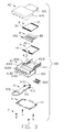
- FIG. 2 is an exploded, perspective view of FIG. 1 ;
- FIG. 3 is similar to the FIG. 2 , but view from another aspect
- FIG. 4 is a partial assembled, perspective view of the cable assembly with a first PCB assembled to an upper cover;
- FIG. 5 is a partial assembled, perspective view of the cable assembly of FIG. 4 with a metallic piece assembled to an upper cover;
- FIG. 6 is a partially assembled, perspective view of the cable assembly of FIG. 5 with a second PCB assembled to the upper cover;
- FIG. 7 is a cross-section view of the cable assembly of FIG. 1 taken along line 7 - 7 ;
- FIG. 8 is a partial enlarged view of FIG. 3 .
- a cable assembly in accordance with the present invention comprises a metallic housing 4 defining a receiving space therein, a pair of first and second PCBs 2 , 3 received in the receiving space, a metallic piece 8 formed between the pair of PCBs 2 , 3 and engaged with the metallic housing 4 , and a latching mechanism 5 assembled to the metallic housing 4 .
- the metallic housing 4 comprises an upper cover 41 and a lower cover 42 assembled with each other.
- the upper cover 41 comprises an expanded first base portion 410 and a relative slim first mating portion 411 extending forwardly from a front edge of the first base portion 410 .
- the first base portion 410 has a top wall 4105 , a pair of side walls 4103 and a rear wall 4102 .
- Four semicircular through holes 4104 are defined in the rear wall 4105 and arranged in a row along transversal direction.
- the first base portion 410 defines four through holes 4101 formed at four corners thereof and extending along a vertical direction.
- the top wall 4105 defines a channel 4120 formed on a top surface 412 and extending along a longitudinal direction, and two pairs of grooves 4122 , 4123 communicated with the channel 4120 and extending along a transversal direction.
- a receiving cavity 4121 is recessed downwardly from the top surface 412 of the top wall 4105 and communicated with the channel 4120 .
- the receiving cavity 4121 is defined in front of the channel 4120 and deeper than the channel 4120 .
- the first mating portion 411 has a top side 4113 and a pair of lateral sides 4114 extending downward from two edges of the top side 4113 .
- the pair of lateral sides 4114 respectively defines two protruding portions 413 formed on an inner surface thereof and extending to a bottom surface of the top side 4113 .
- Each of the protruding portions 413 defines two steps formed on two opposite front and rear ends thereof.
- Each of the protruding portions 413 defines a first section 4131 , a second section 4130 , and a third section 4132 stacked with each other along a vertical direction.
- the first section 4131 is wider than the second section 4130 .
- the second section 4130 is wider than the third section 4132 .
- Two first sections 4131 of two protruding portions 413 formed on a lateral side are connected with each other along a front to rear direction.
- Two protruding portions 413 formed at two lateral sides respectively define a slit 4133 extending along a longitudinal direction.
- the lower cover 42 comprises a second base portion 420 and a second mating portion 421 extending forwardly from a front edge of the second base portion 420 .
- the second base portion 420 has a bottom wall 4201 , a pair of side walls 4203 and a rear wall 4202 extending upwardly from lateral edges and rear edge of the bottom wall 4201 .
- Four semicircular through holes 4204 are formed in the rear wall 4202 and extending along a front to rear direction.
- the four semicircular through holes 4204 are arranged in a row along transversal direction.
- the second base portion 420 respectively defines four screw holes 4206 formed at four corners and in alignment with the through holes 4101 of the upper cover 41 .
- the second mating portion 421 has a bottom side 4211 and a pair of flanges 4212 extending upward from two lateral edges of the bottom side 4211 .
- a plurality of supporting ribs 4213 are respectively arranged at two lateral sides of the bottom side 4211 .
- the lower cover 42 defines a first pair of positioning posts 4205 formed in the second base portion 420 and respectively disposed at the two sides of the second base portion 420 .
- the lower cover 42 further defines a second pair of positioning posts 4210 formed in the second mating portion 421 and respectively disposed at the two sides of the second mating portion 421 .
- the pair of PCBs are disposed in the receiving space of the metallic housing 4 and comprises a first PCB 2 and a second PCB 3 .
- the first and second PCBs 2 , 3 respectively defines a mating portion 21 , 31 with a plurality of conductive pads formed thereon, and a terminating portion 22 , 32 opposite to the mating portion 21 , 31 and with a plurality of conductive pads for terminating to the cable (not shown).
- the first PCB 2 defines two first openings 23 formed on a lateral side and another two first openings 23 formed on another lateral side. Each of two first openings 23 are arranged along a longitudinal direction and spaced apart from each other.
- the second PCB 2 defines two second openings 33 formed on a lateral side and another two second openings 33 formed on another lateral side. Each of two second openings 33 are arranged along a longitudinal direction and spaced apart from each other. Each of the first opening 23 is larger than the second opening 33 .
- the latching mechanism 5 is assembled to a top surface of the metallic housing 4 of the cable assembly 100 .
- the latching mechanism 5 comprises a latching member 52 , a pulling member 51 cooperated with the latching member 52 , and a pulling tape 53 attached to a rear portion of the pulling member 51 .
- the pulling member 51 has a main body 511 which can be received into the channel 4120 , a pair of claw-shaped spring members 5110 arranged at lateral sides of a front segment of the main body 511 and received in the grooves 4123 .
- the pulling member 51 further defines a pair of stoppers 5111 disposed in front of the pair of claw-shaped spring members 5110 and arranged at the lateral sides of the main body 511 and received in the receiving groove 4122 , and a cooperating portion 5112 formed at a front end thereof.
- the latching member 52 is received into the receiving cavity 4121 and comprises a front latching section 520 for latching with a complementary connector, a rear engaging section 521 engaged with the metallic housing 4 , and a middle connecting section 523 connected with the latching section 520 and the engaging section 521 for cooperating with the cooperating portion 5112 .
- the cable assembly 100 further comprises a conductive shell 6 assembled to the top surface 412 of the upper cover 41 and shielding the upper surface 412 and a portion of the latching mechanism 5 .
- the conductive shell 6 defines four circular holes 61 corresponding to the four through holes 4101 and four screw holes 4206 .
- the cable assembly 100 further comprises a metallic piece 8 located between the first PCB 2 and the second PCB 3 .
- the metallic piece 8 defines a pair of inserting portions 82 formed at two sides of a front section thereof and a pair of clamping arms 81 formed on two lateral sides of the rear section thereof. Each of the clamping arms 81 defines a cutout 810 .
- the middle section and the rear section of the metallic piece 8 are covered a layer of plastic to enhance the strength of the metallic piece 8 and prevent the short circuit of the PCB and the wires.
- the cable assembly 100 further comprises four screws 7 respectively passing through the four circular holes 61 , four through holes 4101 and received into the four screw holes 4206 .
- the metallic shell 6 , the upper cover 41 and the lower cover 42 are engaged with each other by the four screws 7 .
- the pair of clamping arms 81 of metallic piece 8 are also engaged to the metallic housing 4 by the two screws 7 .
- the assembling process of the cable assembly 100 made in according to the present invention starts from assembling the first PCB 2 to the upper cover 42 .
- the first PCB 2 is supported by the four first sections 4131 of the four protruding portion 413 , and the four second sections 4130 of the protruding portions 413 are respectively accommodated into the four first openings 23 of the first PCB 2 .
- a movement of the first PCB 2 is restricted by the second sections 4130 along longitudinal direction.
- the metallic piece 8 is assembled in the upper cover 41 , and spaced apart and parallel to the first PCB 2 .
- the inserting portions 82 are respectively inserted into the two slits 4133 of the two protruding portions 413 .
- the front section of the metallic piece 8 is positioned to the housing 4 .
- the second PCB 3 is assembled to the upper cover 41 , and spaced apart and parallel to the metallic piece 8 .
- the four third sections 4132 of the four protruding portions 413 inserted into the second openings 33 of the second PCB 3 .
- the second PCB 3 is supported by the four second sections 4130 of the four protruding portions 413 .
- the movement of the second PCB 3 is restricted along a longitudinal direction.
- the lower cover 42 is assembled to the upper cover 41 .
- the pair of first positioning posts 4210 are passed through two sides of the metallic piece 8 and the second PCB 3 and supported to the front section of the first PCB 2 .
- the pair of the second positioning posts 4205 are also passed through two sides of the metallic piece 8 and the second PCB 3 , and supported to the rear section of the first PCB 2 .
- the second PCB 3 is supported by the supporting ribs 4213 of the lower cover 42 .
- the first and second PCBs 2 and 3 are sandwiched between the upper and the lower covers 41 and 42 .
- the latching mechanism 5 is assembled to the top surface 412 of the upper cover 41 .
- the latching member 52 is received into receiving cavity 4121 of the upper cover 41 .
- the pulling member 51 is received into the channel 4120 and connected with the pulling tap 53 .
- the pulling tap 53 is attached to a rear end of the pulling member 52 . Pulling the pulling tape 53 back, the pulling tape 53 will drive the pulling member 51 backwardly. And the latching member 52 is raised up by the pulling member 51 .
- the conductive shell 6 is assembled to the first top surface of the upper cover 41 , and then the four screws 62 are assembled to the cable assembly 100 .
- the four screws 62 passed through the screw holes 61 , 4101 , 4206 to interconnect with the conductive shell 6 , the upper and the lower cover 41 , 42 .
- a pair of screws 62 may pass through the cutout 810 of the clamping arms 81 of the metallic piece 80 .
- the rear portion of the metallic piece 8 is positioned to the housing 4 by a pair of screws.
- the cable assembly 100 defines four protruding portions 413 formed on an inner surface of the upper cover 41 to position the two PCBs 2 and 3 .
- the cable assembly 100 has simple positioning structure and less component to reduce manufacture cost.
- the cable assembly 100 also defines a metallic piece 8 assembled between the two PCBs 2 and 3 .
- the crosstalk between the two PCBs 2 and 3 will be reduced.
Landscapes
- Details Of Connecting Devices For Male And Female Coupling (AREA)
Abstract
Description
Claims (20)
Applications Claiming Priority (4)
| Application Number | Priority Date | Filing Date | Title |
|---|---|---|---|
| CN201210023971.9 | 2012-02-03 | ||
| CN201210023971.9A CN103247915B (en) | 2012-02-03 | 2012-02-03 | Micro coaxial cable connector assembly and assembly method thereof |
| CN201210031133.6 | 2012-02-13 | ||
| CN2012100311336A CN103247904A (en) | 2012-02-13 | 2012-02-13 | Cable connector component |
Publications (2)
| Publication Number | Publication Date |
|---|---|
| US20130203293A1 US20130203293A1 (en) | 2013-08-08 |
| US9017091B2 true US9017091B2 (en) | 2015-04-28 |
Family
ID=48903279
Family Applications (1)
| Application Number | Title | Priority Date | Filing Date |
|---|---|---|---|
| US13/758,145 Active 2033-06-25 US9017091B2 (en) | 2012-02-03 | 2013-02-04 | Cable assembly having positioning structure for positioning internal printed circuit boards |
Country Status (1)
| Country | Link |
|---|---|
| US (1) | US9017091B2 (en) |
Cited By (13)
| Publication number | Priority date | Publication date | Assignee | Title |
|---|---|---|---|---|
| US20150038004A1 (en) * | 2013-08-01 | 2015-02-05 | Hon Hai Precision Industry Co., Ltd. | Cable connector assembly having simple wiring arrangement between two end connectors |
| US20150117819A1 (en) * | 2013-10-31 | 2015-04-30 | Ming-Feng Ho | Pluggable optical transceiver module |
| US20160285206A1 (en) * | 2015-03-25 | 2016-09-29 | Foxconn Interconnect Technology Limited | Plug connector assembly with shielding shell |
| US20170258140A1 (en) * | 2016-03-11 | 2017-09-14 | Altria Client Services Llc | Multiple dispersion generator e-vaping device |
| US20170310029A1 (en) * | 2014-11-03 | 2017-10-26 | 3M Innovative Properties Company | A connector |
| US10357060B2 (en) | 2016-03-11 | 2019-07-23 | Altria Client Services Llc | E-vaping device cartridge holder |
| US10368580B2 (en) | 2016-03-08 | 2019-08-06 | Altria Client Services Llc | Combined cartridge for electronic vaping device |
| US10368581B2 (en) | 2016-03-11 | 2019-08-06 | Altria Client Services Llc | Multiple dispersion generator e-vaping device |
| US10433580B2 (en) | 2016-03-03 | 2019-10-08 | Altria Client Services Llc | Methods to add menthol, botanic materials, and/or non-botanic materials to a cartridge, and/or an electronic vaping device including the cartridge |
| US10455863B2 (en) | 2016-03-03 | 2019-10-29 | Altria Client Services Llc | Cartridge for electronic vaping device |
| US10833437B2 (en) * | 2018-05-30 | 2020-11-10 | Dongguan Luxshare Technologies Co., Ltd | High-speed connector on high-density mini version chip side |
| US20220360004A1 (en) * | 2021-05-05 | 2022-11-10 | Mellanox Technologies Ltd. | Mechanical shielding for circuit components of a pluggable network interface device |
| US20250203798A1 (en) * | 2023-12-15 | 2025-06-19 | Aptiv Technologies AG | PCB Housing and Assembly Method Therefor |
Families Citing this family (3)
| Publication number | Priority date | Publication date | Assignee | Title |
|---|---|---|---|---|
| TWM565419U (en) * | 2018-02-26 | 2018-08-11 | 宣德科技股份有限公司 | Improved connector combination |
| CN113497373A (en) * | 2020-04-02 | 2021-10-12 | 泰连服务有限公司 | Cable socket connector |
| WO2025221813A1 (en) * | 2024-04-18 | 2025-10-23 | Swift Engineering, Inc. | Flight management systems |
Citations (12)
| Publication number | Priority date | Publication date | Assignee | Title |
|---|---|---|---|---|
| US20040198079A1 (en) * | 2002-10-17 | 2004-10-07 | Aronson Lewis B. | EMI containment transceiver module with floating PCB |
| US7114980B1 (en) | 2005-08-11 | 2006-10-03 | Hon Hai Precision Ind. Co., Ltd | Cable connector assembly with latching mechanism |
| CN2916961Y (en) | 2005-08-26 | 2007-06-27 | 富士康(昆山)电脑接插件有限公司 | Cable Connector Assembly |
| CN200990440Y (en) | 2006-09-14 | 2007-12-12 | 达昌电子科技(苏州)有限公司 | Adapter shell structure |
| CN101173684A (en) | 2006-11-01 | 2008-05-07 | 台达电子工业股份有限公司 | Fan and fan frame thereof |
| CN101552401A (en) | 2008-04-02 | 2009-10-07 | 富士康(昆山)电脑接插件有限公司 | Cable connector assembly |
| US7651342B1 (en) | 2009-01-12 | 2010-01-26 | Hon Hai Precision Ind. Co., Ltd. | Dual-interface electrical connector with anti-crosstalk means therebetween |
| CN201438574U (en) | 2009-02-07 | 2010-04-14 | 富士康(昆山)电脑接插件有限公司 | Cable Connector Assembly |
| CN201868678U (en) | 2010-05-31 | 2011-06-15 | 富士康(昆山)电脑接插件有限公司 | Cable connector assembly |
| CN201887197U (en) | 2010-09-15 | 2011-06-29 | 富士康(昆山)电脑接插件有限公司 | Cable connector component |
| CN201927841U (en) | 2010-12-10 | 2011-08-10 | 富士康(昆山)电脑接插件有限公司 | Cable connector |
| CN103247915A (en) | 2012-02-03 | 2013-08-14 | 富士康(昆山)电脑接插件有限公司 | Cable connector assembly and assembly method thereof |
-
2013
- 2013-02-04 US US13/758,145 patent/US9017091B2/en active Active
Patent Citations (20)
| Publication number | Priority date | Publication date | Assignee | Title |
|---|---|---|---|---|
| US20040198079A1 (en) * | 2002-10-17 | 2004-10-07 | Aronson Lewis B. | EMI containment transceiver module with floating PCB |
| US7114980B1 (en) | 2005-08-11 | 2006-10-03 | Hon Hai Precision Ind. Co., Ltd | Cable connector assembly with latching mechanism |
| CN2909584Y (en) | 2005-08-11 | 2007-06-06 | 富士康(昆山)电脑接插件有限公司 | Cable Connector Assembly |
| US7238040B1 (en) * | 2005-08-11 | 2007-07-03 | Hon Hai Precision Ind. Co., Ltd. | Cable connector assembly with latching mechanism |
| CN2916961Y (en) | 2005-08-26 | 2007-06-27 | 富士康(昆山)电脑接插件有限公司 | Cable Connector Assembly |
| US7413473B2 (en) | 2005-08-26 | 2008-08-19 | Hon Hai Precision Ind. Co., Ltd. | Cable connector assembly with EMI gasket |
| US7445484B2 (en) * | 2005-08-26 | 2008-11-04 | Hon Hai Precision Ind. Co., Ltd. | Plug connector with latching mechanism |
| CN200990440Y (en) | 2006-09-14 | 2007-12-12 | 达昌电子科技(苏州)有限公司 | Adapter shell structure |
| CN101173684A (en) | 2006-11-01 | 2008-05-07 | 台达电子工业股份有限公司 | Fan and fan frame thereof |
| CN101552401A (en) | 2008-04-02 | 2009-10-07 | 富士康(昆山)电脑接插件有限公司 | Cable connector assembly |
| US7651342B1 (en) | 2009-01-12 | 2010-01-26 | Hon Hai Precision Ind. Co., Ltd. | Dual-interface electrical connector with anti-crosstalk means therebetween |
| CN201438574U (en) | 2009-02-07 | 2010-04-14 | 富士康(昆山)电脑接插件有限公司 | Cable Connector Assembly |
| US7938669B2 (en) | 2009-02-07 | 2011-05-10 | Hon Hai Precision Ind. Co. Ltd. | Cable assembly with latching mechanism |
| CN201868678U (en) | 2010-05-31 | 2011-06-15 | 富士康(昆山)电脑接插件有限公司 | Cable connector assembly |
| US8267713B2 (en) * | 2010-05-31 | 2012-09-18 | Hon Hai Precision Ind. Co., Ltd. | Cable connector assembly with latch mechanism having a latch member with pins and a pulling member with holes corresponding to the pins |
| CN201887197U (en) | 2010-09-15 | 2011-06-29 | 富士康(昆山)电脑接插件有限公司 | Cable connector component |
| US8708752B2 (en) * | 2010-09-15 | 2014-04-29 | Hon Hai Precision Industry Co., Ltd. | Cable assembly with lower profile interface |
| CN201927841U (en) | 2010-12-10 | 2011-08-10 | 富士康(昆山)电脑接插件有限公司 | Cable connector |
| US8475198B2 (en) * | 2010-12-10 | 2013-07-02 | Hon Hai Precision Industry Co., Ltd. | Plug connector having an improved latching mechanism |
| CN103247915A (en) | 2012-02-03 | 2013-08-14 | 富士康(昆山)电脑接插件有限公司 | Cable connector assembly and assembly method thereof |
Cited By (32)
| Publication number | Priority date | Publication date | Assignee | Title |
|---|---|---|---|---|
| US9203171B2 (en) * | 2013-08-01 | 2015-12-01 | Hon Hai Precision Industry Co., Ltd. | Cable connector assembly having simple wiring arrangement between two end connectors |
| US20150038004A1 (en) * | 2013-08-01 | 2015-02-05 | Hon Hai Precision Industry Co., Ltd. | Cable connector assembly having simple wiring arrangement between two end connectors |
| US20150117819A1 (en) * | 2013-10-31 | 2015-04-30 | Ming-Feng Ho | Pluggable optical transceiver module |
| US20170310029A1 (en) * | 2014-11-03 | 2017-10-26 | 3M Innovative Properties Company | A connector |
| US11276949B2 (en) | 2014-11-03 | 2022-03-15 | 3M Innovative Properties Company | Shielded connector assembly |
| US10651582B2 (en) * | 2014-11-03 | 2020-05-12 | 3M Innovative Properties Company | Connector |
| US20160285206A1 (en) * | 2015-03-25 | 2016-09-29 | Foxconn Interconnect Technology Limited | Plug connector assembly with shielding shell |
| US9742119B2 (en) * | 2015-03-25 | 2017-08-22 | Foxconn Interconnect Technology Limited | Plug connector assembly with shielding shell |
| US12420034B2 (en) | 2016-03-03 | 2025-09-23 | Altria Client Services Llc | Cartridge for electronic vaping device |
| US12446613B2 (en) | 2016-03-03 | 2025-10-21 | Altria Client Services Llc | Methods to add menthol, botanic materials, and/or non-botanic materials to a cartridge, and/or an electronic vaping device including the cartridge |
| US12178234B2 (en) | 2016-03-03 | 2024-12-31 | Altria Client Services Llc | Methods to add menthol, botanic materials, and/or non-botanic materials to a cartridge, and/or an electronic vaping device including the cartridge |
| US10433580B2 (en) | 2016-03-03 | 2019-10-08 | Altria Client Services Llc | Methods to add menthol, botanic materials, and/or non-botanic materials to a cartridge, and/or an electronic vaping device including the cartridge |
| US10455863B2 (en) | 2016-03-03 | 2019-10-29 | Altria Client Services Llc | Cartridge for electronic vaping device |
| US20200008494A1 (en) | 2016-03-03 | 2020-01-09 | Altria Client Services Llc | Cartridge for electronic vaping device |
| US10368580B2 (en) | 2016-03-08 | 2019-08-06 | Altria Client Services Llc | Combined cartridge for electronic vaping device |
| US12171262B2 (en) | 2016-03-08 | 2024-12-24 | Altria Client Services Llc | Combined cartridge for electronic vaping device |
| US12446622B2 (en) | 2016-03-08 | 2025-10-21 | Altria Client Services Llc | Combined cartridge for electronic vaping device |
| US20210219611A1 (en) | 2016-03-08 | 2021-07-22 | Altria Client Services Llc | Combined cartridge for electronic vaping device |
| US12245632B2 (en) | 2016-03-08 | 2025-03-11 | Altria Client Services Llc | Combined cartridge for electronic vaping device |
| US12439962B2 (en) | 2016-03-11 | 2025-10-14 | Altria Client Services Llc | Multiple dispersion generator e-vaping device |
| US10368581B2 (en) | 2016-03-11 | 2019-08-06 | Altria Client Services Llc | Multiple dispersion generator e-vaping device |
| US12178256B2 (en) | 2016-03-11 | 2024-12-31 | Altria Client Services Llc | Multiple dispersion generator e-vaping device |
| US10357060B2 (en) | 2016-03-11 | 2019-07-23 | Altria Client Services Llc | E-vaping device cartridge holder |
| US12438608B2 (en) | 2016-03-11 | 2025-10-07 | Altria Client Services Llc | E-vaping device cartridge holder |
| US20170258140A1 (en) * | 2016-03-11 | 2017-09-14 | Altria Client Services Llc | Multiple dispersion generator e-vaping device |
| US12453379B2 (en) | 2016-03-11 | 2025-10-28 | Altria Client Services Llc | Multiple dispersion generator e-vaping device |
| US12501928B2 (en) * | 2016-03-11 | 2025-12-23 | Altria Client Services Llc | Multiple dispersion generating e-vaping device having a dual piston cylinder, configured to reduce a transmission of a pressure force from a carbon dioxide capsule to a tank configured to store a pre-aerosol formulation |
| US11322868B2 (en) | 2018-05-30 | 2022-05-03 | Dongguan Luxshare Technologies Co., Ltd | Electrical connector assembly with lockable structures |
| US10833437B2 (en) * | 2018-05-30 | 2020-11-10 | Dongguan Luxshare Technologies Co., Ltd | High-speed connector on high-density mini version chip side |
| US11876315B2 (en) * | 2021-05-05 | 2024-01-16 | Mellanox Technologies, Ltd. | Mechanical shielding for circuit components of a pluggable network interface device |
| US20220360004A1 (en) * | 2021-05-05 | 2022-11-10 | Mellanox Technologies Ltd. | Mechanical shielding for circuit components of a pluggable network interface device |
| US20250203798A1 (en) * | 2023-12-15 | 2025-06-19 | Aptiv Technologies AG | PCB Housing and Assembly Method Therefor |
Also Published As
| Publication number | Publication date |
|---|---|
| US20130203293A1 (en) | 2013-08-08 |
Similar Documents
| Publication | Publication Date | Title |
|---|---|---|
| US9017091B2 (en) | Cable assembly having positioning structure for positioning internal printed circuit boards | |
| US7654831B1 (en) | Cable assembly having improved configuration for suppressing cross-talk | |
| US7938669B2 (en) | Cable assembly with latching mechanism | |
| US7618264B2 (en) | Electrical connector with dual-interface | |
| US7651342B1 (en) | Dual-interface electrical connector with anti-crosstalk means therebetween | |
| US8053667B2 (en) | Housing of quad small form-factor pluggable transceiver module | |
| US7651341B2 (en) | Circuit board assembly with staggered cable arrangement | |
| US9209539B2 (en) | Backplane or midplane communication system and connector | |
| US9812833B2 (en) | SFP socket connector | |
| US8672707B2 (en) | Connector assembly configured to align communication connectors during a mating operation | |
| US8337246B2 (en) | High speed stacked modular jack having shielding plate | |
| US8579661B2 (en) | High speed modular jack | |
| US8579660B2 (en) | High speed modular jack | |
| CN105720419B (en) | Connector block for cable communication system | |
| US10916895B2 (en) | Double-shielded high-speed docking connector | |
| US8002583B2 (en) | Electrical connector system having electromagnetic interference shield and latching features | |
| CN104244661A (en) | Spacers for a cable backplane system | |
| TW201530927A (en) | Cable connector assembly and cable tray having a floatable cable connector | |
| CN104300303A (en) | Guide features for a cable backplane system | |
| US9054468B2 (en) | Electrical connector structure | |
| US6733332B1 (en) | Electrical connector with improved shell | |
| CN103247915B (en) | Micro coaxial cable connector assembly and assembly method thereof | |
| US20130164983A1 (en) | Connector and electronic device having same | |
| CN201259972Y (en) | Four-channel small pluggable transceiver module shell structure | |
| CN205509071U (en) | Micro pluggable connector |
Legal Events
| Date | Code | Title | Description |
|---|---|---|---|
| AS | Assignment |
Owner name: HON HAI PRECISION INDUSTRY CO., LTD., TAIWAN Free format text: ASSIGNMENT OF ASSIGNORS INTEREST;ASSIGNORS:ZHU, QING-MAN;WANG, CHIEN-CHIUNG;WU, JERRY;AND OTHERS;REEL/FRAME:029747/0253 Effective date: 20130123 |
|
| STCF | Information on status: patent grant |
Free format text: PATENTED CASE |
|
| MAFP | Maintenance fee payment |
Free format text: PAYMENT OF MAINTENANCE FEE, 4TH YEAR, LARGE ENTITY (ORIGINAL EVENT CODE: M1551); ENTITY STATUS OF PATENT OWNER: LARGE ENTITY Year of fee payment: 4 |
|
| MAFP | Maintenance fee payment |
Free format text: PAYMENT OF MAINTENANCE FEE, 8TH YEAR, LARGE ENTITY (ORIGINAL EVENT CODE: M1552); ENTITY STATUS OF PATENT OWNER: LARGE ENTITY Year of fee payment: 8 |