US9014984B2 - Resolution matched nonlinear resolution enhancement of well logs - Google Patents
Resolution matched nonlinear resolution enhancement of well logs Download PDFInfo
- Publication number
- US9014984B2 US9014984B2 US13/274,069 US201113274069A US9014984B2 US 9014984 B2 US9014984 B2 US 9014984B2 US 201113274069 A US201113274069 A US 201113274069A US 9014984 B2 US9014984 B2 US 9014984B2
- Authority
- US
- United States
- Prior art keywords
- calculating
- logging data
- formation profile
- estimate
- resolution
- Prior art date
- Legal status (The legal status is an assumption and is not a legal conclusion. Google has not performed a legal analysis and makes no representation as to the accuracy of the status listed.)
- Active, expires
Links
Images


Classifications
-
- G—PHYSICS
- G01—MEASURING; TESTING
- G01V—GEOPHYSICS; GRAVITATIONAL MEASUREMENTS; DETECTING MASSES OR OBJECTS; TAGS
- G01V1/00—Seismology; Seismic or acoustic prospecting or detecting
- G01V1/40—Seismology; Seismic or acoustic prospecting or detecting specially adapted for well-logging
- G01V1/44—Seismology; Seismic or acoustic prospecting or detecting specially adapted for well-logging using generators and receivers in the same well
- G01V1/48—Processing data
-
- G—PHYSICS
- G01—MEASURING; TESTING
- G01V—GEOPHYSICS; GRAVITATIONAL MEASUREMENTS; DETECTING MASSES OR OBJECTS; TAGS
- G01V11/00—Prospecting or detecting by methods combining techniques covered by two or more of main groups G01V1/00 - G01V9/00
-
- G—PHYSICS
- G01—MEASURING; TESTING
- G01V—GEOPHYSICS; GRAVITATIONAL MEASUREMENTS; DETECTING MASSES OR OBJECTS; TAGS
- G01V3/00—Electric or magnetic prospecting or detecting; Measuring magnetic field characteristics of the earth, e.g. declination, deviation
- G01V3/38—Processing data, e.g. for analysis, for interpretation, for correction
-
- G—PHYSICS
- G01—MEASURING; TESTING
- G01V—GEOPHYSICS; GRAVITATIONAL MEASUREMENTS; DETECTING MASSES OR OBJECTS; TAGS
- G01V5/00—Prospecting or detecting by the use of ionising radiation, e.g. of natural or induced radioactivity
- G01V5/04—Prospecting or detecting by the use of ionising radiation, e.g. of natural or induced radioactivity specially adapted for well-logging
Definitions
- the present invention relates to the field of well logging, and in particular to a nonlinear resolution-matched technique for enhancing the resolution of well logs.
- Logging tools can be categorized in terms of their operating tool physics. They include resistivity tools, nuclear tools, acoustics tools, Nuclear Magnetic Resonance (NMR) tools, etc.
- logging tools can be grouped based on the scenario in which the tool operates, e.g., Wireline Logging (WL) tools and Logging While Drilling (LWD) tools.
- WL tools are lowered into a well by attaching them to a wireline.
- Wireline Logging is the traditional way for collecting well logs. LWD is a more recent development in which logging tools are mounted on drill collars and logging is performed while drilling is going on.
- Linear deconvolution utilizes deconvolution filters to deconvolve tool response to a target response function with a well-defined shape and resolution.
- target functions are Gaussian functions with 1 ft., 2 ft., or 4 ft. resolutions.
- a modern logging tool commonly has multiple depths of investigations as in the case of WL array induction and LWD propagation tools. The measurement at different depths of investigation usually produces different vertical resolutions.
- Linear deconvolution not only enhances vertical resolutions but also matches resolutions of all measurements at different depths of investigations at a preselected resolution.
- linear deconvolution is limited by the operating tool physics. When the tool response is very nonlinear, linear deconvolution will produce unacceptable artifacts. For induction tools, linearity worsens when the resistivity contrast in formation beds increases. High-contrast formations are not uncommon in well logging. For example, a shale formation can have resistivity at around 1 Ohm-m, while an anhydrite formation nearby can have resistivity at thousands of Ohm-m. Linearity also worsens when the operating frequency is higher. Thus, linear deconvolution has been recognized as insufficient in many scenarios.
- Nonlinear resolution enhancement techniques are typically more robust than linear techniques, especially for logs acquired in high-contrast formations.
- One such method is described in U.S. Pat. No. 5,967,906, which recites a nonlinear enhancement similar to a Van Cittert iterative deconvolution technique that utilizes nonlinear modeling of the tool response rather than the response functions as in linear deconvolution techniques.
- the enhancement is performed on a square log and the enhanced square log is subsequently smoothed to produce the reduced resolution.
- a disadvantage of this enhancement technique is the amount of correction required on the original log can be very large for each iteration, which may lead to instabilities in a Van Cittert nonlinear enhancement process. Therefore, subsequent smoothing is always necessary for this technique as the last step in processing.
- the technique mentions how to provide matched resolutions among different tool spacings it fails to describe how to match resolutions at a preselected value, e.g. a fixed 2 ft. resolution.
- Embodiments described herein provide a way to perform nonlinear resolution enhancement of well logs.
- the nonlinear enhancement uses a modified Van Cittert nonlinear enhancement that avoids the instabilities described above and can provide resolution matched results at a predetermined resolution.
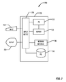
- FIG. 1 is a block diagram illustrating elements of a wireline logging system according to one embodiment.
- FIG. 2 is a flowchart illustrating processing of a well log according to one embodiment.
- FIG. 3 is flowchart illustrating processing of a well log according to another embodiment.
- FIG. 4 is a graph illustrating an example of raw well log curves prior to enhancement.
- FIG. 5 is a graph illustrating enhanced well log curves matched to a 2 ft. resolution according to one embodiment.
- FIG. 6 is a graph illustrating enhanced well log curves matched to a 4 ft. resolution according to one embodiment.
- FIG. 7 is a block diagram illustrating a computer system for use in processing the well log signals according to one embodiment.
- the techniques described below are set forth in terms of an induction tool that performs resistivity measurements, the present invention is not so limited, and the disclosed techniques may be used with other types of logging tools, including acoustic and nuclear well logging tools.
- the techniques disclosed below may be used in applications other than well logging, including various image processing and signal processing applications.
- FIG. 1 is a block diagram illustrating a simplified WL system 100 according to one embodiment.
- a WL sensor array 150 is lowered into a borehole 140 on wireline 120 , typically using a lowering/raising mechanism 130 for positioning the array 150 in the borehole 140 .
- the wireline is typically connected electrically to a computer 110 where the signals generated by the array 150 may be received and captured for analysis purposes.
- Other conventional elements known to the well logging industry may be present in addition to those illustrated in FIG. 1 , but are omitted for clarity.
- the computer 110 may also analyze the wireline data captured from the array 150 ; in other embodiments, the wireline data captured by the computer 110 is sent to another computer system (not shown) for analysis.
- the computer 110 is illustrated in FIG. 1 as local to the well, the computer 110 may be located remotely, and the well logging data transmitted from the well site to the computer 110 using any desired transmission technique, wireless or wired.
- the computer 110 is local to the well site and may capture and store the logging data, then transmit the logging data to a remote computer for analysis, using any type of data transmission techniques, including shipment of physical media on which the logging data has been received and stored.
- the computer 110 may perform some analysis on the received logging data and transmit the raw and/or analyzed received logging data to the remote computer for further analysis.
- a sensor array is lowered into the borehole as part of a drilling string, instead of as an element positioned on a wireline 120 .
- data from the sensor array is transmitted from the drill string as signals to a computer 110 , wirelessly or by wire, for capture and possible analysis.
- the LWD sensor array is typically mounted in a drill collar above the bit suspended beneath the surface of the earth from a drilling rig by drill pipe. Unlike a WL embodiment, LWD logging by definition is performed while drilling the well.
- the various embodiments described herein may be used in either a WL or LWD configuration.
- the traditional dual induction tool records these two apparent resistivity measurements at two different depths of investigation, typically designated as ILM (medium measurement) and ILD (deep measurement). These curves may be combined with other curves, such as a Spherically Focused Log (SFL) curve.
- SFL Spherically Focused Log
- a frequency effect causes the induction response of the typical induction logging tool to change even for the same tool transmitter-receiver spacing.
- lower frequencies typically investigate a deeper area than higher frequencies.
- the frequency effect is nonlinear, which results in a nonlinear induction logging tool response, which may make the use of nonlinear enhancement techniques such as the embodiments described below more useful and accurate than linear enhancement techniques, even though nonlinear techniques may require greater computing resources and take longer to produce results than linear techniques.
- a vertical processing module (VPM) stage enhances and matches logs from an induction logging tool at one or more predetermined resolutions. This is accomplished with an improved Van Cittert method, as described in more detail below.
- the VPM stage may be followed by a radial processing module (RPM) stage to produce fixed depth of investigation curves.
- RPM radial processing module
- FIG. 2 is a flowchart illustrating processing steps for a VPM stage according to one embodiment.
- an initial estimate is made of the formation profile. In later iterations, this initial estimate is the estimate generated by the previous iteration of the technique.
- a 2D forward modeling technique is used to simulate the response of the logging tool.
- a nonlinear 2D modeling algorithm is used in block 220 .
- a numerical mode matching method may be used to provide 2D forward modeling, but any desired type of 2D modeling technique known to the art may be used.
- the 2D forward modeling technique preferably includes borehole and bed modeling, in order to account for borehole effects.
- the current iteration of the enhancement processing is then performed in block 230 , using the modified Van Cittert formula set forth below.
- the VPM stage completes by outputting the processed curves. Otherwise, the iterative non-linear procedure repeats beginning at block 210 .
- the predetermined criteria comprise an integer number of iterations, for example 5 or 6 iterations. Other embodiments may use one or more other predetermined criteria as desired, including how well the simulated data matches the field data.
- the predetermined number may be selected by an analyst experimentally, based on how well the model agrees with the raw logging data. There is a tradeoff between accuracy and speed, because more iterations may produce a higher accuracy, but at a cost of additional processing time and resources.
- the predetermined number may vary based on various factors, such as the type of logging or the tool being used. For example, nuclear logging might result in a different fixed maximum number of iterations being used than induction logging.
- FIG. 3 is a flowchart illustrating an embodiment that includes both a VPM stage 200 and an RPM stage 300 .
- a radial inversion technique may be used on the processed curves output by the VPM stage 200 to yield an inverted radial profile, using any known desired radial inversion technique.
- fixed depth of investigation (DOI) curves may be computed by convolving the inverted radial profiles produced by block 310 with a set of preselected target functions.
- DOI depth of investigation
- Other radial processing techniques may be used in addition to or instead of the radial inversion and convolution techniques illustrated in FIG. 3 .
- multi-frequency radial inversion may be inappropriate, since at zero conductivity the skin effect (of any order) disappears.
- MFIT multi-frequency inversion threshold
- an interpolation and/or extrapolation technique known to the art may be used to generate the fixed depth of investigation curves.
- embodiments of this technique may provide matched resolutions at preselected resolution values, e.g. 1 ft., 2 ft., and 4 ft. resolutions.
- embodiments of the nonlinear resolution enhancement technique may provide matched resolutions at preselected fixed values in a stable manner.
- T(f) is the resolution-enhanced signal
- g is the raw signal
- f is the current guess of the true formation profile, initially estimated from the raw log
- A is a nonlinear modeling operator
- ⁇ is a relaxation factor. The simplest form treats every sample point as an independent bed.
- Van Cittert calculations as typical in nonlinear enhancement techniques, are iteratively performed.
- a problem with the unmodified Van Cittert technique is that the enhanced resolution is not controlled.
- the unmodified Van Cittert algorithm can be unstable. Typical end-desired deliverables in induction log processing are matched resolution curves, e.g. 2 ft. resolution curves achieved through linear deconvolution.
- the unmodified Van Cittert algorithm does not teach how to provide resolution matching at a pre-determined fixed value, e.g. 2 ft.
- f is the current estimate of the true formation profile. In one embodiment, in the first iteration, f is determined by picking bed boundaries from g. In later iterations, f is determined by picking bed boundaries from T new (f) of the previous iteration. Thus, f is updated on every iteration of the procedure.
- T new (f) is the updated enhanced estimate of the enhanced logging curve and T old (f) is the previous estimate of the enhanced logging curve.
- T old (f) is set to f; in later iterations, T old (f) is the value of T new (f) from the previous iteration.
- T new (f) is output as the result of the computation.
- F is a Gaussian filter with a pre-selected resolution, e.g. 2 ft.
- g is the raw signal.
- A is the nonlinear forward modeling operator. As with f, A changes with each iteration of the procedure, unlike a linear modeling approach, where A would remain unchanged.
- a nonlinear forward modeling operator, calculated every iteration of the procedure illustrated in FIG. 2 above, allows taking into account the nonlinear nature of the logging tool response.
- ⁇ 1 , and ⁇ 2 are relaxation factors.
- the (g ⁇ Af) portion of the formula provides an enhancement factor that modifies the previous enhanced estimate of the enhanced well logging curve.
- the (f ⁇ F*f) portion of the formula provides a resolution-matched stability factor that is subtracted from the enhancement factor to reduce or eliminate instabilities, as well as to cause the calculation to be resolution-matched.
- the use of the Gaussian filter F causes the resulting enhanced signal to be resolution matched. Any desired resolution may be used to enhance the native resolution of the logging tool.
- the amount of resolution enhancement that is possible is typically limited by the tool physics and the tool sampling rate, according to the Nyquist sampling theorem. If there measurements produced by the tool have low resolution and high noise, then when the resolution enhancement is attempted, the noise may overwhelm the true signal if too much resolution enhancement is attempted.
- the raw signal g is assumed to be a clean signal with little noise, and enhancement to a 2 ft. resolution typically does not create deleterious noise enhancement effects.
- Gaussian filters F with resolutions of 1 ft., 2 ft., and 4 ft.
- the nonlinear forward modeling operator A may be selected experimentally. Typically, a model of the logging tool is run in a model of the formation in which the actual tool is to be used for logging, using a preselected number of layers in the formation model, such that Af equals the simulated log response. If the logging tool has a linear response, then A may be a simple matrix. However, typical logging tools produce a nonlinear response, and A is a nonlinear operator. In one embodiment, the nonlinear operator may be produced by numerical mode matching techniques such as those described by W. Chew, et al. “Diffraction of Axisymmetric Waves in a Borehole by Boundary Discontinuities,” Geophysics, Vol. 49, No. 5 (September-October 1984), pp. 1584-1596. Other techniques that may be used include finite element analysis techniques and finite difference techniques.
- the relaxation factors ⁇ 1 , and ⁇ 2 may be simple numerical values, typically between 0.9 and 1.1. In alternate embodiments, the relaxation factors may be a nonlinear smooth function, such as a polynomial function. The use of relaxation factors is well known in Van Cittert-type calculations, and the specific relaxation factors may be selected experimentally for a specific logging tool.
- the stability factor (f ⁇ F*f) addresses the stability of the computation, by subtracting out instabilities produced by (g ⁇ Af). Each iteration therefore is constrained by subtracting out excessive enhancement, avoiding the need to post-perform smoothing or other operations to attempt to eliminate the instabilities in the Van Cittert formula.
- the stability factor causes the calculation of T new (f) to be resolution matched to the desired predetermined fixed resolution.
- the disclosed techniques allow obtaining matched resolutions. Unlike conventional nonlinear enhancement techniques, various embodiments of the disclosed techniques try to get an updated log with a matched preselected resolution, e.g. a 2 ft. resolution at every update, instead of obtaining a square log, then smoothing the square log to get the final results. This is why the new techniques are more stable, because in the new method stabilization is enforced at every update, while the conventional techniques do not address stability until the final step, when it is often too late to do so.
- a matched preselected resolution e.g. a 2 ft. resolution
- FIG. 4 is a graph 400 illustrating a processing example using the techniques described above.
- the logging tool is an induction logging tool with two spacings, ILM and ILD at 20 KHz.
- the raw measurements were generated by computer simulation.
- the resistivity of a formation is typically designated as R t .
- ILM and ILD curves may be generated by the well logging tool at more than one frequency.
- the enhancement techniques described above may be performed on the curves of each frequency.
- the R t curve 430 is the true profile of a simulated 10 foot wide bed, with an 8 inch borehole filled with 1 Ohm-m mud, thus borehole correction is automatically accounted for.
- Raw curve 410 is the medium spacing (ILM) curve
- raw curve 420 is the deep spacing (ILD) curve.
- ILM curve 410 and ILM curve 420 do not have matched resolutions, i.e., the two curves do not align with each other.
- FIG. 5 is a graph 500 illustrating enhanced ILM and ILD curves processed according to one embodiment of the technique illustrated in FIG. 2 .
- the ILM and ILD curves 510 and 520 are matched to the true profile curve 430 at a predefined resolution, in this example 2 ft., a resolution frequently used because bed thickness is often better defined by 2 ft. curves than at other resolutions.
- FIG. 6 is a graph 600 illustrating enhanced ILM and ILD curves processed according to one embodiment of the technique illustrated in FIG. 2 , using a 4 ft. resolution instead of the 2 ft. resolution of FIG. 5 .
- the ILM and ILD curves 610 and 620 are matched to the true profile 430 at the 4 ft. resolution, but do not define the bed thickness as well as the 2 ft. curves, being more “smeared away” above and below the bed.
- 4 ft. resolution curves may be helpful when environmental noise in the measurement is prominent.
- Example computer 700 for use in performing a nonlinear resolution-matched resolution enhancement technique is illustrated in block diagram form.
- Example computer 700 comprises a system unit 710 which may be optionally connected to an input device or system 760 (e.g., keyboard, mouse, touch screen, etc.) and display 770 .
- a program storage device 780 (sometimes referred to as a hard disc) is included with the system unit 710 .
- Also included with system unit 710 is a network interface 740 for communication via a network with other computing and corporate infrastructure devices (not shown).
- Network interface 740 may be included within system unit 710 or be external to system unit 710 . In either case, system unit 710 is be communicatively coupled to network interface 740 .
- Network interface 740 may be communicatively coupled to the well logging sensor array 150 for receiving raw well logging data from the well logging sensor array 150 .
- Other techniques for communicatively coupling the computer 700 to the well logging sensor array 150 that may employ other interfaces or features of the computer 700 to allow the computer 700 to receive the raw well logging data may be used, including the transport of physical media containing the raw well logging data from a device coupled to the well logging sensor array 150 to the computer 700 .
- Program storage device 780 represents any form of non-volatile storage including, but not limited to, all forms of optical and magnetic, including solid-state, storage elements, including removable media, and may be included within system unit 710 or be external to system unit 710 .
- Program storage device 780 may be used for storage of software to control system unit 710 , data for use by the computer 700 , or both.
- System unit 710 may be programmed to perform methods in accordance with this disclosure (an example of which is in FIG. 2 ).
- System unit 710 comprises a processor unit (PU) 720 , input-output (I/O) interface 750 and memory 730 .
- Processing unit 720 may include any programmable controller device.
- Memory 730 may include one or more memory modules and comprise random access memory (RAM), read only memory (ROM), programmable read only memory (PROM), programmable read-write memory, and solid-state memory.
- RAM random access memory
- ROM read only memory
- PROM programmable read only memory
- PU 720 may also include some internal memory including, for example, cache memory.
Landscapes
- Life Sciences & Earth Sciences (AREA)
- Physics & Mathematics (AREA)
- General Life Sciences & Earth Sciences (AREA)
- General Physics & Mathematics (AREA)
- Geophysics (AREA)
- Engineering & Computer Science (AREA)
- Environmental & Geological Engineering (AREA)
- Geology (AREA)
- Remote Sensing (AREA)
- Acoustics & Sound (AREA)
- High Energy & Nuclear Physics (AREA)
- Geophysics And Detection Of Objects (AREA)
Abstract
Description
T(f)=f+τ(g−Af)
T new(f)=T old(f)+[τ1(g−Af)−τ1(f−F*f)]
T new(f)=T old(f)+τ[(g−Af)−(f−F*f)]
f=T old(f)
T new(f)=T old(f)+τ[(g−AT old(f))−(T old(f)−F*T old(f))]
Claims (20)
Priority Applications (2)
| Application Number | Priority Date | Filing Date | Title |
|---|---|---|---|
| US13/274,069 US9014984B2 (en) | 2011-10-14 | 2011-10-14 | Resolution matched nonlinear resolution enhancement of well logs |
| GB201218362A GB2495634B (en) | 2011-10-14 | 2012-10-12 | Resolution matched nonlinear resolution enhancement of well logs |
Applications Claiming Priority (1)
| Application Number | Priority Date | Filing Date | Title |
|---|---|---|---|
| US13/274,069 US9014984B2 (en) | 2011-10-14 | 2011-10-14 | Resolution matched nonlinear resolution enhancement of well logs |
Publications (2)
| Publication Number | Publication Date |
|---|---|
| US20130096834A1 US20130096834A1 (en) | 2013-04-18 |
| US9014984B2 true US9014984B2 (en) | 2015-04-21 |
Family
ID=47324701
Family Applications (1)
| Application Number | Title | Priority Date | Filing Date |
|---|---|---|---|
| US13/274,069 Active 2033-02-14 US9014984B2 (en) | 2011-10-14 | 2011-10-14 | Resolution matched nonlinear resolution enhancement of well logs |
Country Status (2)
| Country | Link |
|---|---|
| US (1) | US9014984B2 (en) |
| GB (1) | GB2495634B (en) |
Families Citing this family (3)
| Publication number | Priority date | Publication date | Assignee | Title |
|---|---|---|---|---|
| US20170139077A1 (en) * | 2015-03-17 | 2017-05-18 | Halliburton Energy Services, Inc | Optimization of Downhole Logging Tool Data Resolution |
| CN111255436B (en) * | 2020-01-17 | 2023-07-28 | 成都理工大学 | A Method for Improving the Measurement Curve Quality of HDIL Array Induction Logging Tool |
| CN117077442B (en) * | 2023-10-16 | 2024-02-09 | 浙江省气象科学研究所 | Topography-based tropical cyclone precipitation correction method, terminal and medium |
Citations (6)
| Publication number | Priority date | Publication date | Assignee | Title |
|---|---|---|---|---|
| US5329235A (en) | 1992-11-02 | 1994-07-12 | Western Atlas International, Inc. | Method for processing signals from an MWD electromagnetic resistivity logging tool |
| US5867806A (en) | 1996-03-13 | 1999-02-02 | Halliburton Energy Services, Inc. | System and method for performing inversion on LWD resistivity logs with enhanced resolution |
| US6337568B1 (en) * | 1999-10-25 | 2002-01-08 | Tarek A. Tutunji | System and method for enhanced vertical resolution magnetic resonance imaging logs |
| WO2004027682A2 (en) | 2002-09-20 | 2004-04-01 | Halliburton Energy Services, Inc. | Simultaneous resolution enhancement and dip correction of resistivity logs through nonlinear iterative deconvolution |
| US6810331B2 (en) | 2002-09-25 | 2004-10-26 | Halliburton Energy Services, Inc. | Fixed-depth of investigation log for multi-spacing multi-frequency LWD resistivity tools |
| US7184367B2 (en) * | 2003-03-27 | 2007-02-27 | Exxonmobil Upstream Research Company | Method to convert seismic traces into petrophysical property logs |
-
2011
- 2011-10-14 US US13/274,069 patent/US9014984B2/en active Active
-
2012
- 2012-10-12 GB GB201218362A patent/GB2495634B/en active Active
Patent Citations (7)
| Publication number | Priority date | Publication date | Assignee | Title |
|---|---|---|---|---|
| US5329235A (en) | 1992-11-02 | 1994-07-12 | Western Atlas International, Inc. | Method for processing signals from an MWD electromagnetic resistivity logging tool |
| US5867806A (en) | 1996-03-13 | 1999-02-02 | Halliburton Energy Services, Inc. | System and method for performing inversion on LWD resistivity logs with enhanced resolution |
| US6337568B1 (en) * | 1999-10-25 | 2002-01-08 | Tarek A. Tutunji | System and method for enhanced vertical resolution magnetic resonance imaging logs |
| WO2004027682A2 (en) | 2002-09-20 | 2004-04-01 | Halliburton Energy Services, Inc. | Simultaneous resolution enhancement and dip correction of resistivity logs through nonlinear iterative deconvolution |
| US6885943B2 (en) | 2002-09-20 | 2005-04-26 | Halliburton Energy Services, Inc. | Simultaneous resolution enhancement and dip correction of resistivity logs through nonlinear iterative deconvolution |
| US6810331B2 (en) | 2002-09-25 | 2004-10-26 | Halliburton Energy Services, Inc. | Fixed-depth of investigation log for multi-spacing multi-frequency LWD resistivity tools |
| US7184367B2 (en) * | 2003-03-27 | 2007-02-27 | Exxonmobil Upstream Research Company | Method to convert seismic traces into petrophysical property logs |
Non-Patent Citations (2)
| Title |
|---|
| Chew, et al. "Diffraction of axisymmetric waves in a borehole by bed boundary discontinuities," Geophysics. vol. 49, No. 10 (Oct. 1984): p. 1566-1595, 6 FIGS. |
| Great Britain Search Report for GB Patent Application No. GB1218362.0 dated Feb. 7, 2013, 5 pages. |
Also Published As
| Publication number | Publication date |
|---|---|
| GB201218362D0 (en) | 2012-11-28 |
| US20130096834A1 (en) | 2013-04-18 |
| GB2495634A (en) | 2013-04-17 |
| GB2495634B (en) | 2013-09-18 |
Similar Documents
| Publication | Publication Date | Title |
|---|---|---|
| RU2337404C1 (en) | Computer method for modelling during drilling and stratified underground fraction visualisation | |
| US11230922B2 (en) | Fracture interpretation with resistivity and sonic logs in biaxial anisotropic formations | |
| US11409016B2 (en) | Correlating strata surfaces across well logs | |
| AU2014357611B2 (en) | Digital core model construction | |
| US12332157B2 (en) | Methods and systems for determining reservoir and fracture properties | |
| US9229127B2 (en) | Methods program code, computer readable media, and apparatus for predicting matrix permeability by optimization and variance correction of K-nearest neighbors | |
| US10385658B2 (en) | In-situ wellbore, core and cuttings information system | |
| US11156738B2 (en) | Permeability anisotropy assessment in subsurface anisotropic formations | |
| WO2017084454A1 (en) | Stratum component optimization determination method and device | |
| WO2013112827A1 (en) | Method of estimating a subterranean formation property | |
| US10352162B2 (en) | Cleanup model parameterization, approximation, and sensitivity | |
| CN110794476B (en) | An inversion method based on the phase control of the off-solution | |
| US20160070019A1 (en) | Estimating subsurface formation and invasion properties | |
| CN113874864A (en) | Train machine learning systems using hard and soft constraints | |
| US9014984B2 (en) | Resolution matched nonlinear resolution enhancement of well logs | |
| US10488547B2 (en) | Estimating subsurface formation and invasion properties | |
| CN112415581B (en) | Fracture-cave reservoir inversion method and system | |
| CN120370407B (en) | Deep coal seam fracture density azimuth seismic inversion method and device | |
| EP3980817A1 (en) | Sequential estimation while drilling | |
| US10527749B2 (en) | Methods and approaches for geomechanical stratigraphic systems | |
| EP4619791A1 (en) | Use of machine learning techniques to enhance and accelerate inversion methods for the interpretation of deep directional resistivity measurements | |
| WO2016057312A1 (en) | Correcting for monitoring electrodes current leakage in galvanic tools | |
| US11549355B2 (en) | Avoiding geological formation boundaries during drilling operations | |
| US20250284023A1 (en) | Fast approach for dispersion curve stacking, visualization and calibration | |
| CN117368966A (en) | Reservoir porosity prediction method, device, equipment and medium based on deep learning |
Legal Events
| Date | Code | Title | Description |
|---|---|---|---|
| AS | Assignment |
Owner name: WEATHERFORD/LAMB, INC., TEXAS Free format text: ASSIGNMENT OF ASSIGNORS INTEREST;ASSIGNOR:HU, GUOYU;REEL/FRAME:027067/0092 Effective date: 20111014 |
|
| AS | Assignment |
Owner name: WEATHERFORD TECHNOLOGY HOLDINGS, LLC, TEXAS Free format text: ASSIGNMENT OF ASSIGNORS INTEREST;ASSIGNOR:WEATHERFORD/LAMB, INC.;REEL/FRAME:034526/0272 Effective date: 20140901 |
|
| STCF | Information on status: patent grant |
Free format text: PATENTED CASE |
|
| MAFP | Maintenance fee payment |
Free format text: PAYMENT OF MAINTENANCE FEE, 4TH YEAR, LARGE ENTITY (ORIGINAL EVENT CODE: M1551); ENTITY STATUS OF PATENT OWNER: LARGE ENTITY Year of fee payment: 4 |
|
| AS | Assignment |
Owner name: WELLS FARGO BANK NATIONAL ASSOCIATION AS AGENT, TEXAS Free format text: SECURITY INTEREST;ASSIGNORS:WEATHERFORD TECHNOLOGY HOLDINGS LLC;WEATHERFORD NETHERLANDS B.V.;WEATHERFORD NORGE AS;AND OTHERS;REEL/FRAME:051891/0089 Effective date: 20191213 |
|
| AS | Assignment |
Owner name: DEUTSCHE BANK TRUST COMPANY AMERICAS, AS ADMINISTR Free format text: SECURITY INTEREST;ASSIGNORS:WEATHERFORD TECHNOLOGY HOLDINGS, LLC;WEATHERFORD NETHERLANDS B.V.;WEATHERFORD NORGE AS;AND OTHERS;REEL/FRAME:051419/0140 Effective date: 20191213 Owner name: DEUTSCHE BANK TRUST COMPANY AMERICAS, AS ADMINISTRATIVE AGENT, NEW YORK Free format text: SECURITY INTEREST;ASSIGNORS:WEATHERFORD TECHNOLOGY HOLDINGS, LLC;WEATHERFORD NETHERLANDS B.V.;WEATHERFORD NORGE AS;AND OTHERS;REEL/FRAME:051419/0140 Effective date: 20191213 |
|
| AS | Assignment |
Owner name: PRECISION ENERGY SERVICES, INC., TEXAS Free format text: RELEASE BY SECURED PARTY;ASSIGNOR:WELLS FARGO BANK, NATIONAL ASSOCIATION;REEL/FRAME:053838/0323 Effective date: 20200828 Owner name: WEATHERFORD U.K. LIMITED, TEXAS Free format text: RELEASE BY SECURED PARTY;ASSIGNOR:WELLS FARGO BANK, NATIONAL ASSOCIATION;REEL/FRAME:053838/0323 Effective date: 20200828 Owner name: WEATHERFORD NETHERLANDS B.V., TEXAS Free format text: RELEASE BY SECURED PARTY;ASSIGNOR:WELLS FARGO BANK, NATIONAL ASSOCIATION;REEL/FRAME:053838/0323 Effective date: 20200828 Owner name: WEATHERFORD TECHNOLOGY HOLDINGS, LLC, TEXAS Free format text: RELEASE BY SECURED PARTY;ASSIGNOR:WELLS FARGO BANK, NATIONAL ASSOCIATION;REEL/FRAME:053838/0323 Effective date: 20200828 Owner name: WEATHERFORD SWITZERLAND TRADING AND DEVELOPMENT GMBH, TEXAS Free format text: RELEASE BY SECURED PARTY;ASSIGNOR:WELLS FARGO BANK, NATIONAL ASSOCIATION;REEL/FRAME:053838/0323 Effective date: 20200828 Owner name: WEATHERFORD NORGE AS, TEXAS Free format text: RELEASE BY SECURED PARTY;ASSIGNOR:WELLS FARGO BANK, NATIONAL ASSOCIATION;REEL/FRAME:053838/0323 Effective date: 20200828 Owner name: HIGH PRESSURE INTEGRITY, INC., TEXAS Free format text: RELEASE BY SECURED PARTY;ASSIGNOR:WELLS FARGO BANK, NATIONAL ASSOCIATION;REEL/FRAME:053838/0323 Effective date: 20200828 Owner name: WEATHERFORD CANADA LTD., TEXAS Free format text: RELEASE BY SECURED PARTY;ASSIGNOR:WELLS FARGO BANK, NATIONAL ASSOCIATION;REEL/FRAME:053838/0323 Effective date: 20200828 Owner name: PRECISION ENERGY SERVICES ULC, TEXAS Free format text: RELEASE BY SECURED PARTY;ASSIGNOR:WELLS FARGO BANK, NATIONAL ASSOCIATION;REEL/FRAME:053838/0323 Effective date: 20200828 Owner name: WILMINGTON TRUST, NATIONAL ASSOCIATION, MINNESOTA Free format text: SECURITY INTEREST;ASSIGNORS:WEATHERFORD TECHNOLOGY HOLDINGS, LLC;WEATHERFORD NETHERLANDS B.V.;WEATHERFORD NORGE AS;AND OTHERS;REEL/FRAME:054288/0302 Effective date: 20200828 |
|
| AS | Assignment |
Owner name: WILMINGTON TRUST, NATIONAL ASSOCIATION, MINNESOTA Free format text: SECURITY INTEREST;ASSIGNORS:WEATHERFORD TECHNOLOGY HOLDINGS, LLC;WEATHERFORD NETHERLANDS B.V.;WEATHERFORD NORGE AS;AND OTHERS;REEL/FRAME:057683/0706 Effective date: 20210930 Owner name: WEATHERFORD U.K. LIMITED, TEXAS Free format text: RELEASE BY SECURED PARTY;ASSIGNOR:WILMINGTON TRUST, NATIONAL ASSOCIATION;REEL/FRAME:057683/0423 Effective date: 20210930 Owner name: PRECISION ENERGY SERVICES ULC, TEXAS Free format text: RELEASE BY SECURED PARTY;ASSIGNOR:WILMINGTON TRUST, NATIONAL ASSOCIATION;REEL/FRAME:057683/0423 Effective date: 20210930 Owner name: WEATHERFORD SWITZERLAND TRADING AND DEVELOPMENT GMBH, TEXAS Free format text: RELEASE BY SECURED PARTY;ASSIGNOR:WILMINGTON TRUST, NATIONAL ASSOCIATION;REEL/FRAME:057683/0423 Effective date: 20210930 Owner name: WEATHERFORD CANADA LTD, TEXAS Free format text: RELEASE BY SECURED PARTY;ASSIGNOR:WILMINGTON TRUST, NATIONAL ASSOCIATION;REEL/FRAME:057683/0423 Effective date: 20210930 Owner name: PRECISION ENERGY SERVICES, INC., TEXAS Free format text: RELEASE BY SECURED PARTY;ASSIGNOR:WILMINGTON TRUST, NATIONAL ASSOCIATION;REEL/FRAME:057683/0423 Effective date: 20210930 Owner name: HIGH PRESSURE INTEGRITY, INC., TEXAS Free format text: RELEASE BY SECURED PARTY;ASSIGNOR:WILMINGTON TRUST, NATIONAL ASSOCIATION;REEL/FRAME:057683/0423 Effective date: 20210930 Owner name: WEATHERFORD NORGE AS, TEXAS Free format text: RELEASE BY SECURED PARTY;ASSIGNOR:WILMINGTON TRUST, NATIONAL ASSOCIATION;REEL/FRAME:057683/0423 Effective date: 20210930 Owner name: WEATHERFORD NETHERLANDS B.V., TEXAS Free format text: RELEASE BY SECURED PARTY;ASSIGNOR:WILMINGTON TRUST, NATIONAL ASSOCIATION;REEL/FRAME:057683/0423 Effective date: 20210930 Owner name: WEATHERFORD TECHNOLOGY HOLDINGS, LLC, TEXAS Free format text: RELEASE BY SECURED PARTY;ASSIGNOR:WILMINGTON TRUST, NATIONAL ASSOCIATION;REEL/FRAME:057683/0423 Effective date: 20210930 Owner name: WEATHERFORD TECHNOLOGY HOLDINGS, LLC, TEXAS Free format text: RELEASE OF SECURITY INTEREST;ASSIGNOR:WILMINGTON TRUST, NATIONAL ASSOCIATION;REEL/FRAME:057683/0423 Effective date: 20210930 Owner name: WEATHERFORD NETHERLANDS B.V., TEXAS Free format text: RELEASE OF SECURITY INTEREST;ASSIGNOR:WILMINGTON TRUST, NATIONAL ASSOCIATION;REEL/FRAME:057683/0423 Effective date: 20210930 Owner name: WEATHERFORD NORGE AS, TEXAS Free format text: RELEASE OF SECURITY INTEREST;ASSIGNOR:WILMINGTON TRUST, NATIONAL ASSOCIATION;REEL/FRAME:057683/0423 Effective date: 20210930 Owner name: HIGH PRESSURE INTEGRITY, INC., TEXAS Free format text: RELEASE OF SECURITY INTEREST;ASSIGNOR:WILMINGTON TRUST, NATIONAL ASSOCIATION;REEL/FRAME:057683/0423 Effective date: 20210930 Owner name: PRECISION ENERGY SERVICES, INC., TEXAS Free format text: RELEASE OF SECURITY INTEREST;ASSIGNOR:WILMINGTON TRUST, NATIONAL ASSOCIATION;REEL/FRAME:057683/0423 Effective date: 20210930 Owner name: WEATHERFORD CANADA LTD, TEXAS Free format text: RELEASE OF SECURITY INTEREST;ASSIGNOR:WILMINGTON TRUST, NATIONAL ASSOCIATION;REEL/FRAME:057683/0423 Effective date: 20210930 Owner name: WEATHERFORD SWITZERLAND TRADING AND DEVELOPMENT GMBH, TEXAS Free format text: RELEASE OF SECURITY INTEREST;ASSIGNOR:WILMINGTON TRUST, NATIONAL ASSOCIATION;REEL/FRAME:057683/0423 Effective date: 20210930 Owner name: PRECISION ENERGY SERVICES ULC, TEXAS Free format text: RELEASE OF SECURITY INTEREST;ASSIGNOR:WILMINGTON TRUST, NATIONAL ASSOCIATION;REEL/FRAME:057683/0423 Effective date: 20210930 Owner name: WEATHERFORD U.K. LIMITED, TEXAS Free format text: RELEASE OF SECURITY INTEREST;ASSIGNOR:WILMINGTON TRUST, NATIONAL ASSOCIATION;REEL/FRAME:057683/0423 Effective date: 20210930 |
|
| MAFP | Maintenance fee payment |
Free format text: PAYMENT OF MAINTENANCE FEE, 8TH YEAR, LARGE ENTITY (ORIGINAL EVENT CODE: M1552); ENTITY STATUS OF PATENT OWNER: LARGE ENTITY Year of fee payment: 8 |
|
| AS | Assignment |
Owner name: WELLS FARGO BANK, NATIONAL ASSOCIATION, NORTH CAROLINA Free format text: PATENT SECURITY INTEREST ASSIGNMENT AGREEMENT;ASSIGNOR:DEUTSCHE BANK TRUST COMPANY AMERICAS;REEL/FRAME:063470/0629 Effective date: 20230131 |