US8991997B2 - Device for leveling ink under a thermal gradient - Google Patents
Device for leveling ink under a thermal gradient Download PDFInfo
- Publication number
- US8991997B2 US8991997B2 US14/031,336 US201314031336A US8991997B2 US 8991997 B2 US8991997 B2 US 8991997B2 US 201314031336 A US201314031336 A US 201314031336A US 8991997 B2 US8991997 B2 US 8991997B2
- Authority
- US
- United States
- Prior art keywords
- ink
- substrate
- temperature
- ink layer
- steam
- Prior art date
- Legal status (The legal status is an assumption and is not a legal conclusion. Google has not performed a legal analysis and makes no representation as to the accuracy of the status listed.)
- Active
Links
Images


Classifications
-
- B—PERFORMING OPERATIONS; TRANSPORTING
- B41—PRINTING; LINING MACHINES; TYPEWRITERS; STAMPS
- B41J—TYPEWRITERS; SELECTIVE PRINTING MECHANISMS, i.e. MECHANISMS PRINTING OTHERWISE THAN FROM A FORME; CORRECTION OF TYPOGRAPHICAL ERRORS
- B41J11/00—Devices or arrangements of selective printing mechanisms, e.g. ink-jet printers or thermal printers, for supporting or handling copy material in sheet or web form
- B41J11/0015—Devices or arrangements of selective printing mechanisms, e.g. ink-jet printers or thermal printers, for supporting or handling copy material in sheet or web form for treating before, during or after printing or for uniform coating or laminating the copy material before or after printing
- B41J11/002—Curing or drying the ink on the copy materials, e.g. by heating or irradiating
-
- B—PERFORMING OPERATIONS; TRANSPORTING
- B41—PRINTING; LINING MACHINES; TYPEWRITERS; STAMPS
- B41J—TYPEWRITERS; SELECTIVE PRINTING MECHANISMS, i.e. MECHANISMS PRINTING OTHERWISE THAN FROM A FORME; CORRECTION OF TYPOGRAPHICAL ERRORS
- B41J11/00—Devices or arrangements of selective printing mechanisms, e.g. ink-jet printers or thermal printers, for supporting or handling copy material in sheet or web form
- B41J11/0015—Devices or arrangements of selective printing mechanisms, e.g. ink-jet printers or thermal printers, for supporting or handling copy material in sheet or web form for treating before, during or after printing or for uniform coating or laminating the copy material before or after printing
- B41J11/002—Curing or drying the ink on the copy materials, e.g. by heating or irradiating
- B41J11/0021—Curing or drying the ink on the copy materials, e.g. by heating or irradiating using irradiation
- B41J11/00214—Curing or drying the ink on the copy materials, e.g. by heating or irradiating using irradiation using UV radiation
-
- B—PERFORMING OPERATIONS; TRANSPORTING
- B41—PRINTING; LINING MACHINES; TYPEWRITERS; STAMPS
- B41J—TYPEWRITERS; SELECTIVE PRINTING MECHANISMS, i.e. MECHANISMS PRINTING OTHERWISE THAN FROM A FORME; CORRECTION OF TYPOGRAPHICAL ERRORS
- B41J11/00—Devices or arrangements of selective printing mechanisms, e.g. ink-jet printers or thermal printers, for supporting or handling copy material in sheet or web form
- B41J11/0015—Devices or arrangements of selective printing mechanisms, e.g. ink-jet printers or thermal printers, for supporting or handling copy material in sheet or web form for treating before, during or after printing or for uniform coating or laminating the copy material before or after printing
- B41J11/002—Curing or drying the ink on the copy materials, e.g. by heating or irradiating
- B41J11/0024—Curing or drying the ink on the copy materials, e.g. by heating or irradiating using conduction means, e.g. by using a heated platen
-
- B—PERFORMING OPERATIONS; TRANSPORTING
- B41—PRINTING; LINING MACHINES; TYPEWRITERS; STAMPS
- B41J—TYPEWRITERS; SELECTIVE PRINTING MECHANISMS, i.e. MECHANISMS PRINTING OTHERWISE THAN FROM A FORME; CORRECTION OF TYPOGRAPHICAL ERRORS
- B41J29/00—Details of, or accessories for, typewriters or selective printing mechanisms not otherwise provided for
- B41J29/377—Cooling or ventilating arrangements
-
- B—PERFORMING OPERATIONS; TRANSPORTING
- B41—PRINTING; LINING MACHINES; TYPEWRITERS; STAMPS
- B41M—PRINTING, DUPLICATING, MARKING, OR COPYING PROCESSES; COLOUR PRINTING
- B41M7/00—After-treatment of prints, e.g. heating, irradiating, setting of the ink, protection of the printed stock
Definitions
- the noun substrate shall refer to the medium upon which the ink is applied, including, but not limited to, a porous substrate such as paper.
- the adjective porous as applied to the substrate refers to the fact that the substrate includes pores that are permeable by the ink.
- FIG. 1 is a graph that illustrates the viscosity as a function of temperature for a typical gel ink that is compatible with example embodiments.
- FIG. 2 is a graph that illustrates the temperature gradient across a substrate and an ink layer in accordance with example embodiments.
- FIG. 3 is a schematic diagram illustrating a model paper and ink stack that is heated symmetrically, from both sides of the paper, using hot air or alternatively, steam.
- FIG. 4 is a graph that illustrates temperature profiles in the model ink and paper stack of FIG. 3 at different times.
- FIG. 5 is a schematic diagram that illustrates a model for estimating how quickly an ink layer will wick into a capillary of a porous substrate.
- FIG. 6 is a schematic diagram that illustrates a model for estimating a time scale for the reflow characteristics of an ink layer that exhibits an initial surface roughness.
- FIG. 7 is a schematic diagram that illustrates a model for estimating the velocity of a top layer of ink due to an applied shear force.
- FIG. 8 is a schematic profile view diagram illustrating some components included in an ink leveling device in accordance with example embodiments.
- FIG. 9 is a schematic top view diagram of the device of FIG. 8 .
- FIG. 10 is a schematic diagram that illustrates a thermal model for the ink leveling device of FIG. 8 .
- FIG. 11 is a graph illustrating the temperature as a function of time at selected positions across the thermal model of FIG. 10 after steam is applied.
- FIG. 12 is a graph illustrating the steady-state temperature profile of the thermal model of FIG. 10 after steam is applied.
- FIG. 13 is a schematic profile view diagram illustrating some components of an ink leveling device in accordance with other example embodiments.
- FIG. 14 is a graph illustrating the temperature as a function of time at selected positions across the thermal model of FIG. 10 after hot air is applied.
- FIG. 15 is a graph illustrating the steady-state temperature profile of the thermal model of FIG. 10 after hot air is applied.
- FIG. 16 is a schematic profile view diagram illustrating some components of an ink leveling device in accordance with other example embodiments.
- FIG. 17 is a graph illustrating the temperature as a function of time at selected positions across the thermal model of FIG. 10 after steam, then hot air, are sequentially applied.
- FIG. 18 is a graph illustrating temperature profiles of the thermal model of FIG. 10 at different times after steam, then hot air, are sequentially applied.
- FIG. 19 is a schematic profile view diagram illustrating some components of an ink leveling device in accordance with other example embodiments.
- FIG. 20 is a schematic diagram that illustrates a thermal model for the ink leveling device of FIG. 19 .
- FIG. 21 is a graph illustrating the temperature as a function of time at selected positions across the thermal model of FIG. 20 when steam is introduced into the heating chamber and cool air is introduced into the cooling chamber.
- FIG. 22 is a graph illustrating the temperature as a function of time at selected positions across the thermal model of FIG. 20 when hot air is introduced into the heating chamber and cool air is introduced into the cooling chamber.
- FIG. 23 is a graph illustrating the steady-state temperature profile of the thermal model of FIG. 20 when hot air is introduced into the heating chamber and cool air is introduced into the cooling chamber.
- FIG. 24 is a graph illustrating the temperature as a function of time at selected positions across the thermal model of FIG. 20 when steam, then hot air, are introduced into the heating chamber and cool air is introduced into the cooling chamber.
- FIG. 25 is a graph illustrating temperature profiles of the thermal model of FIG. 20 at different times when steam and hot air are sequentially introduced into the heating chamber and cool air is introduced into the cooling chamber.
- FIG. 26 is a schematic profile view diagram illustrating some components included of an ink leveling device 2600 in accordance with example embodiments.
- the presently described embodiments disclose methods and apparatus for contactless leveling of inks that create a steep thermal gradient through a substrate where the ink is being applied. Most of the substrate is maintained below a viscosity temperature threshold T 0 , while the ink itself is heated above the viscosity temperature threshold T 0 .
- This approach advantageously allows the top surface temperature to be maintained above the viscosity threshold for a sufficient time to allow the ink to flow laterally.
- the approach also maintains most or all of the substrate below the viscosity threshold to prevent excessive seepage or “bleed-through” of the ink into the porous substrate.
- steam is employed to rapidly heat the ink and the surface of the porous substrate to a high temperature at which the viscosity of the ink becomes low enough to allow local reflow under surface/interfacial tension forces and under the capillary interaction with the substrate.
- the high temperature is below the boiling point of water, but this is not a requirement.
- a steep thermal gradient through the porous substrate provides a means to maintain the ink in the gel state near the top surface of the substrate, preventing the ink from penetrating a significant way into the substrate.
- the thermal gradient can be created by cooling the bottom side of the substrate while heating the top (ink) side of the substrate.
- hot air may be used to heat the ink and the ink side of the porous substrate.
- a combination of both steam and hot air may be used.
- FIG. 1 is a graph 100 that illustrates the viscosity as a function of temperature for a typical gel ink that is compatible with example embodiments.
- the graph 100 shows that the viscosity profile for the gel ink has a rather sharp threshold.
- threshold temperature T 0 is defined as the temperature at which the viscosity of the gel ink is approximately 50% of the maximum viscosity. It should be recognized that this definition of threshold temperature is somewhat arbitrary and could just as easily be defined as, for example, a temperature at which the viscosity of the gel ink is approximately 10% of the maximum viscosity.
- the threshold temperature T 0 should be selected such that above the threshold temperature T 0 the gel ink can flow relatively easily.
- the ink is heated above the threshold temperature T 0 so that the ink may flow readily under the influence of surface/interfacial tension and interfacial capillary forces and/or externally supplied shear forces.
- the gel ink is applied to the substrate at room temperature before being heated. In other embodiments, the gel ink can be heated before being applied to the substrate.
- a thermal gradient may be established across the substrate. The thermal gradient is established such that the temperature is below the threshold temperature T 0 for most, and more preferably all, locations in the substrate.
- the thermal gradient may be established by cooling the bottom of the substrate while heating the top of the substrate, either before or after the ink is applied to the top of the substrate. Because the temperature within the substrate rapidly drops below the threshold temperature T 0 as the depth into the substrate increases, the imbibed ink rapidly loses its ability to move further into the porous substrate. Thus, one can maintain the top surface temperature for sufficient time to allow the applied ink to flow laterally while avoiding significant seepage or “bleed-through” into the porous substrate.
- FIG. 2 is a graph 200 that illustrates a thermal gradient 205 across a substrate 210 and an ink layer 220 that is in accordance with example embodiments.
- Graph 200 reveals that the temperature of the substrate decreases linearly as the depth into the substrate increases, and that the majority of the substrate exhibits a temperature that is below the threshold temperature T 0 .
- T 0 the threshold temperature
- the rate at which temperature decreases across the ink layer 220 and the substrate 210 in graph 200 are shown as being equal, this may not always be the case.
- other temperature gradients in accordance with example embodiments need not be linear and may vary from the shape of thermal gradient 205 depending on the specific material and composition of the substrate.
- heating of the substrate may be accomplished using the application of hot air or some other fluid.
- convective heat transfer which is defined as a mechanism of heat transfer that occurs because of the bulk motion or observable movement of a fluid.
- the heating of the substrate may be accomplished using the application of steam. This involves both convective heat transfer and condensation heat transfer. Condensation heat transfer is much faster than convective heat transfer alone due to the release of latent heat associated with the phase change of water vapor to a liquid state.
- FIG. 3 is a schematic diagram illustrating a model paper and ink stack 300 that can be heated symmetrically, from both sides of the paper, using hot air or alternatively, steam.
- an ink layer 310 is disposed on a paper layer 320 .
- the ink layer 310 is 20 ⁇ m thick and the paper layer is 100 ⁇ m thick.
- Table 2 illustrates that the amount of time it takes a position in the paper/ink stack 300 to reach the threshold temperature of the ink (70° C.) using convection heat transfer is over an order of magnitude greater compared to condensation heat transfer. In either case, however, because of the good heat conduction within the ink and paper layers 310 , 320 , the temperature equalizes across both layers within 10 to 20 ms.
- FIG. 4 is a graph 400 that illustrates temperature profiles in the model ink and paper stack 300 of FIG. 3 at different times.
- the zero point corresponds to the bottom of the paper layer 320 , and every division thereafter is equivalent to 20 ⁇ m.
- the interface between the ink layer 310 and the paper layer 320 corresponds to the numeral five (5).
- the temperature profiles in graph 400 were calculated at 25 ms intervals.
- synchronization and coordination of the various events that occur will be an important consideration. For example, the time required to heat a substrate layer or ink layer to reach a desired temperature, the velocity at which the substrate is transported through the ink-leveling system or device, the rate at which the substrate layer or ink layer cools, etc., may all be important quantities to know for the system designer.
- FIG. 5 is a schematic diagram that illustrates a model 500 for estimating how quickly an ink layer will wick into a capillary of a porous substrate.
- An ink layer 510 of height H is disposed above a straight capillary 520 of radius R that exists in a substrate.
- the time it takes for the ink from the ink layer 510 to be drawn down into the capillary 520 by a length L is given by equation 1 below, where ⁇ is the viscosity of the ink (10 ⁇ 2 Pa ⁇ s), ⁇ is the surface tension of the ink (10 ⁇ 3 N ⁇ m), and ⁇ is the wetting angle (30 degrees).
- ⁇ is the viscosity of the ink (10 ⁇ 2 Pa ⁇ s)
- ⁇ is the surface tension of the ink (10 ⁇ 3 N ⁇ m)
- ⁇ is the wetting angle (30 degrees).
- Table 3 which appears below this paragraph, presents the results of using equation (1) to estimate how long it takes for ink to be wicked into two differently sized capillaries for selected values of L. As shown in Table 3, a thin ink layer (10-20 ⁇ m) will be pulled into the substrate within 10-100 milliseconds. It should be remembered that equation (1) provides only an estimate. In reality, as the ink moves into the porous substrate it does not always encounter a straight capillary, but rather a network of pores of different diameters. The actual wicking dynamics, therefore, may be slower than the estimates shown in Table 3.
- R 0.5 ⁇ m
- R 0.05 ⁇ m L ( ⁇ m) t (ms) t (ms) 1 0.06 0.6 5 1.5 15 10 6 60 20 24 240 50 150 1500
- FIG. 6 is a schematic diagram that illustrates a model 600 for estimating a time scale for the reflow characteristics of an ink layer that exhibits an initial surface roughness.
- an ink layer 610 is disposed on the substrate 630 .
- the ink layer 610 exhibits a surface roughness that is characterized as having an initial radius ( ⁇ ).
- T 0 the threshold temperature
- the connected portions of the ink layer 610 will reflow due to surface tension forces, and look like the ink layer 620 at time t>0.
- the surface flatness is given by ( ⁇ ), where ⁇ is a measure of the surface flatness compared to the initial state.
- the radius R for the surface structure of the ink layer 620 can be defined based upon the measure of surface flatness ⁇ and the initial radius ⁇ of ink layer 610 , as given by equation (2) below.
- Equation (3) The time required for the ink layer 610 to reflow to achieve the surface characteristics of ink layer 620 is given by equation (3) below, where ⁇ is the viscosity of the ink and ⁇ is the surface tension of the ink. As can be seen from equation (3), the time required is directly proportional to the viscosity ⁇ of the ink and the radius R of the surface structure.
- Equation (4) which appears below, is obtained by substituting equation (2) into equation (3). Equation (4) expresses the reflow time required as a function of the initial surface structure a and the desired measure of surface flatness ⁇ .
- Table 4 which appears below this paragraph, presents the results of calculating, using equations 2 and 4, the radius R of the surface structure and the required time to achieve the radius R for different values of the desired surface flatness ⁇ .
- the initial radius a was 21 ⁇ m
- the viscosity ⁇ of the ink was 10 ⁇ 2 Pa ⁇ s
- the surface tension a of the ink was 10 ⁇ 3 N ⁇ m.
- the values for a, ⁇ , and ⁇ are merely examples that are chosen for illustrative purposes.
- leveling of the ink layer may also be accomplished by using an external shear force.
- the external shear force may be applied using an air knife, which directs a jet of air across the ink layer.
- the temperature of the air may be set at a desired temperature. Applying a shear force may be important in situations where the ink layer is discontinuous, and needs to be pushed onto blank substrate areas.
- FIG. 7 is a schematic diagram illustrating a model 700 for estimating the velocity of a top layer of ink due to an applied shear force.
- an ink layer 720 is disposed on a substrate 730 , such as paper.
- An air layer 710 is disposed above the ink layer 720 . It is assumed that no slippage occurs between the layers 710 , 720 , and 730 , that the velocity gradient in the air layer 710 is 10 m/s over 1 mm, that the thickness of the ink layer 720 is 10 ⁇ m, and that the substrate 730 moves in the horizontal direction (x-direction) at a velocity of 1 m/s.
- Equation (7) which is an expression for the velocity of the top layer of ink, results from these assumptions.
- H ink is a constant resulting from the derivation of equation (7) from equations (5) and (6).
- the time required to move the surface element of ink is 10 ms and 100 ms, respectively. Multiplying 10 ms and 100 ms by the velocity of the paper (1 m/s) results in the length L of the shear zone required to achieve this surface movement.
- a shear zone of 10 mm is required in order to move the surface element of ink by 10 ⁇ m.
- a shear zone of 100 mm is required.
- FIG. 8 is a schematic profile view diagram illustrating some components included in an ink leveling device 800 in accordance with example embodiments.
- FIG. 9 is a schematic top view diagram of the ink leveling device 800 .
- the device 800 includes a cylinder 830 and a steam chamber 820 in proximity to the cylinder.
- a substrate 810 such as porous paper 810 , is transported through the steam chamber 820 using the cylinder 830 .
- An unleveled ink layer (not shown) is disposed on the upper side of the substrate 810 . As the substrate 810 passes through the steam chamber 820 , the unleveled ink is heated above a threshold temperature T 0 of the ink.
- the porous paper 810 is in the form of a web, which is known in the art as a long, continuous length of paper that is stored in a roll. After printing, the web is cut into sheets. This is sometimes referred to as a web-fed system.
- the invention is not limited to web-fed systems however, as alternative embodiments of the invention may be sheet-fed systems, or a system in which the paper is cut to a desired size before the ink is applied.
- the cylinder 830 is cooled and rotates about an axis of rotation of the cylinder, and the bottom of the substrate 810 is in contact with the cooled cylinder as is passes through the steam chamber 820 .
- the cylinder 830 may be stationary and use a cold air bearing (not shown) that uses a cushion of cooled air to maintain the substrate 810 at some distance from the surface of the cylinder. In this case, the substrate 810 would be pulled through the steam chamber 820 by another roller (not shown).
- the cooled cylinder and cold air bearing are just two possible examples.
- the term “cooling surface” will be used in this disclosure to refer generally to any surface that can cool the substrate, either by contact with the substrate or by some other means.
- the cooled cylinder and cold air bearing are two examples of a device that includes a cooling surface. It will be apparent to those of skill in the art that other known substrate transport mechanisms are suitable for use with example embodiments.
- the unleveled ink layer on the top side of the substrate is heated above a threshold temperature T 0 of the ink, while the bottom side is held at a low temperature by the cylinder 830 .
- This creates a thermal gradient through the substrate 810 such as the thermal gradient 205 shown in FIG. 2 .
- heating the unleveled ink layer allows the ink layer to reflow, thereby leveling the ink.
- the substrate 810 leaves the steam chamber 820 it is actively cooled in a quench zone 835 of the cylinder 830 , although the quench zone 835 is optional.
- the substrate 810 is shown as coming into contact with the cylinder 830 at approximately the same time it enters the steam chamber 820 .
- the relative position at which the substrate 810 contacts the cylinder 830 may be altered so that the substrate 810 is actively chilled by the cylinder (through contact with the cylinder or by chilled air bearings on the cylinder) before the substrate enters the steam chamber 820 . This is done to ensure that the substrate 810 and ink layer are cooled to well below the threshold temperature T 0 of the ink across its entire thickness to better maintain the desired steep thermal gradient as the substrate passes through the steam chamber 820 .
- FIG. 10 is a schematic diagram that illustrates a thermal model 1000 for the ink leveling device 800 of FIG. 8 .
- the model 1000 shows the ink layer 1020 disposed on the substrate 810 , while the cylinder 830 is separated from the bottom of the substrate by an air gap 1010 .
- the air gap 1010 models the heat resistance between the substrate 810 and the cylinder 830 .
- the thicknesses of the ink layer 1020 , the substrate 810 , and the air gap 1010 are chosen as 20, 100, and 25 ⁇ m, respectively.
- Above the ink layer 1020 there is a region 1030 where the steam is applied.
- the physical properties of the ink layer 1020 and the substrate 810 are assumed to be the same as those for the ink layer 310 and the paper layer 320 , respectively, as summarized in Table 1 above.
- FIG. 11 is a graph 1100 illustrating the temperature as a function of time at selected positions across the model 1000 of FIG. 10 after steam is applied.
- FIG. 12 is a graph 1200 illustrating the steady-state temperature profile of the model 1000 of FIG. 10 after steam is applied.
- zero (0) on the x-axis corresponds to the interface between the air gap 1010 and the substrate 810 .
- the associated heat transfer coefficients (h CV , h CD ) for convective heat transfer and condensation heat transfer for steam at this temperature is 100 W/m 2 ⁇ k, and 2000 W/m 2 ⁇ k, respectively.
- FIGS. 11 and 12 illustrate that while steam is very efficient for quickly heating the ink layer 1020 to a desired temperature, in order to maintain a threshold temperature T 0 just under the ink layer 1020 , the cylinder 830 must be kept at about ⁇ 43° C. This causes a relatively high heat flux even under steady-state conditions (about 6.5 ⁇ 10 4 W/m 2 ), and it also results in a relatively high condensation rate (about 27 g/cm 2 ), which may not be desirable.
- FIG. 13 is a schematic profile view diagram illustrating some components of an ink leveling device 1300 in accordance with other example embodiments.
- Device 1300 is similar to device 800 of FIG. 8 , but in device 1300 there is a hot air chamber 1320 in proximity to the cylinder 830 rather than the steam chamber 820 . Because the devices are so similar, the thermal model 1000 of FIG. 10 that was used for simulating device 800 may also be used to simulate device 1300 , where the only adjustment needed is the introduction of hot air into region 1030 rather than steam.
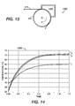
- FIG. 14 is a graph 1400 illustrating the temperature as a function of time at selected positions across the model 1000 of FIG. 10 after hot air is applied.
- FIG. 15 is a graph 1500 illustrating the steady-state temperature profile of the model 1000 of FIG. 10 after hot air is applied.
- zero (0) on the x-axis corresponds to the interface between the air gap 1010 and the substrate 810 .
- the associated heat transfer coefficient (h CV ) for convective heat transfer for hot air at this temperature is 100 W/m 2 ⁇ k.
- FIGS. 14 and 15 illustrate that hot air is significantly less efficient than steam for heating the ink layer 1020 to a desired temperature.
- the temperature across the entire substrate 810 may be kept below the threshold temperature T 0 by maintaining the temperature of the cylinder at only 48° C.
- the steady-state heat flux in this case is about 1.28 ⁇ 10 4 W/m 2 , about 80% less than the case where steam was used, with no associated condensation.
- the ink-leveling devices according to FIG. 8 and FIG. 13 can both establish a desired thermal gradient within the substrate 810 , the performance of the steam-only option and the hot air only option for heating the ink layer 1020 is not ideal.
- the steam-only option has a high associated steady-state heat flux, while the hot air only option takes a relatively long time to raise the ink layer to the desired temperature.
- the inventors have found that one can advantageously obtain the advantages of both methods by quickly heating the ink layer 1020 to above the threshold temperature T 0 using steam, then switching to hot air to slow down the heating rate. This avoids raising the temperature of the substrate 810 above T 0 .
- FIG. 16 is a schematic profile view diagram illustrating some components of an ink leveling device 1600 in accordance with other example embodiments.
- Device 1600 is similar to device 800 of FIG. 8 and device 1300 of FIG. 13 , but in device 1600 there is a dual-chamber chamber 1620 .
- the dual-chamber chamber 1620 includes a steam chamber 1630 and a hot air chamber 1640 . It should be apparent that in alternative embodiments, two separate chambers, one using steam and one using hot air, may be used in a sequential manner.
- the thermal model 1000 of FIG. 10 that was used for simulating device 800 and 1300 may also be used to simulate device 1600 , where the only modification needed is that steam is first introduced into region 1030 for a first period of time, then hot air is introduced into region 1030 for a second period of time.
- steam and hot air are actually introduced into two physically different regions, but for purposes of the simulation this simplification is acceptable because the steam and hot air are not being applied to the substrate 810 simultaneously.
- FIG. 17 is a graph 1700 illustrating the temperature as a function of time at selected positions across the model 1000 of FIG. 10 after steam, then hot air, are sequentially applied.
- FIG. 18 is a graph 1800 illustrating temperature profiles of the thermal model 1000 of FIG. 10 at different times after steam, then hot air, are sequentially applied.
- one (1) on the x-axis corresponds to the interface between the ink layer 1020 and the substrate 810 .
- steam at a temperature of 200° C. was first applied for t ⁇ 60 ms, followed by application of hot air at 200° C. for t>60 ms.
- the associated heat transfer coefficient (h CV ) for convective heat transfer for hot air at this temperature is 100 W/m 2 ⁇ k
- the associated heat transfer coefficient (h CD ) for condensation heat transfer during the steam application phase is 2000 W/m 2 ⁇ k.
- FIGS. 17 and 18 illustrate that, by choosing the correct geometries and temperatures for both the steam chamber 1630 and hot air chamber 1640 , a well-defined time window can be created in which the ink temperature is above the threshold temperature T 0 , while substantially all of the substrate temperature stays below the threshold temperature T 0 .
- the T3 trace of FIG. 17 shows that the top of the ink layer 1020 is above the threshold temperature T 0 for about 70 ms, while the T2 trace shows that the bottom of the ink layer is above the threshold temperature T 0 for about 40 ms.
- FIG. 18 illustrates that only about 3-4 ⁇ m of the substrate is raised above the threshold temperature T 0 .
- FIG. 19 is a schematic profile view diagram illustrating some components of an ink leveling device 1900 in accordance with other example embodiments.
- the ink leveling device 1900 includes a heating/cooling chamber 1910 that is operable to establish the desired thermal gradient across the substrate 1940 .
- the substrate 1940 with an ink layer (not shown) disposed thereon, enters the heating/cooling chamber 1910 at entry 1950 and leaves the heating/cooling chamber 1910 at exit 1960 .
- a variety of mechanisms may be used to draw the substrate 1940 through the heating/cooling chamber 1910 . These mechanisms are well understood and are not critical for an understanding of the described embodiment.
- the heating/cooling chamber 1910 is divided into a heating chamber 1920 and a cooling chamber 1930 .
- the substrate 1940 separates the heating chamber 1920 from the cooling chamber 1930 .
- the impedance of the gap between the heating chamber 1920 and the cooling chamber 1930 is high enough so that minimal thermal exchange occurs between the heating chamber and the cooling chamber.
- the heating chamber 1920 of the heating/cooling chamber 1910 may heat the substrate 1940 using steam or hot air, but the best performance is achieved by sequentially heating the substrate using first steam, followed by an application of hot air.
- the cooling chamber 1930 is preferably used to introduce cool air on the underside of the substrate 1940 , but any suitable cool fluid may be used.
- the heating chamber 1920 and the cooling chamber 1930 establish the desired thermal gradient across the substrate 1940 .
- FIG. 20 is a schematic diagram that illustrates a thermal model 2000 for the ink leveling device 1900 of FIG. 19 .
- the thermal model 2000 shows an ink layer 2010 disposed on the substrate 1940 .
- the thicknesses of the ink layer 2010 and the substrate 1940 are chosen as 20 and 100 ⁇ m, respectively.
- the physical properties of the ink layer 2010 and the substrate 1940 are assumed to be the same as those for the ink layer 310 and the paper layer 320 , respectively, as summarized in Table 1 above.
- FIG. 21 is a graph 2100 illustrating the temperature as a function of time at selected positions across the thermal model 2000 of FIG. 20 when steam is introduced into the heating chamber 1920 and cool air is introduced into the cooling chamber 1930 .
- the associated heat transfer coefficients (h CV , h CD ) for convective heat transfer and condensation heat transfer for steam at this temperature is 100 W/m 2 ⁇ k, and 2000 W/m 2 ⁇ k, respectively.
- the associated heat transfer coefficient (h CV ) for convective heat transfer for cool air at this temperature is 100 W/m 2 ⁇ k.
- graph 2100 illustrates that there is about a 20 ms window over which the top of the ink layer 2010 (trace T3) is above the threshold temperature T 0 (70° C.), while the top of the substrate 1940 (trace T2) is below the threshold temperature T 0 .
- FIG. 22 is a graph 2200 illustrating the temperature as a function of time at selected positions across the thermal model 2000 of FIG. 20 when hot air is introduced into the heating chamber 1920 and cool air is introduced into the cooling chamber 1930 .
- FIG. 23 is a graph 2300 illustrating the steady-state temperature profile of the thermal model 2000 of FIG. 20 when hot air is introduced into the heating chamber 1920 and cool air is introduced into the cooling chamber 1930 . It was assumed that the temperature of the hot air applied in the heating chamber 1920 was at 84° C. It was further assumed that the temperature of the cool air applied in the cooling chamber 1930 was at 55° C. The associated heat transfer coefficient (h CV ) for convective heat transfer of the air was assumed to be 100 W/m 2 ⁇ k.
- FIGS. 22 and 23 illustrate that hot air is significantly less efficient than steam for heating the ink layer 2010 to a desired temperature.
- the temperature across the entire substrate 1940 may be kept below the threshold temperature T 0 by supplying cooling air at 55° C.
- the steady-state heat flux in this case is about 1.4 ⁇ 10 3 W/m 2 .
- FIG. 24 is a graph 2400 illustrating the temperature as a function of time at selected positions across the thermal model 2000 of FIG. 20 when steam, then air, is introduced into the heating chamber 1920 and cool air is introduced into the cooling chamber 1930 .
- FIG. 25 is a graph 2500 illustrating temperature profiles of the thermal model 2000 of FIG. 20 at different times when steam and hot air are sequentially introduced into the heating chamber 1920 and cool air is introduced into the cooling chamber 1930 .
- FIGS. 24 and 25 illustrate that by choosing the correct geometries and temperatures for both the heating chamber 1920 and cooling chamber 1930 , a well-defined time window can be created in which the temperature of the ink layer 2010 is above the threshold temperature T 0 , while most of the substrate 1940 temperature is below the threshold temperature T 0 .
- the T3 trace of FIG. 24 shows that the top of the ink layer 2010 is above the threshold temperature T 0 for about 70 ms, while the T2 trace shows that the top of the substrate 1940 is concurrently above the threshold temperature T 0 for about 40 ms.
- FIG. 25 illustrates that only about 3-4 ⁇ m of the substrate 1940 is raised above the threshold temperature T 0 .
- the length of the heating zone and cooling zone can be set to achieve the desired time for reflow of the ink at low viscosity. Additionally, it may be desirable to provide better control of the ink motion and optionally the subsequent cooling of the substrate and the quenching of the ink.
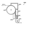
- FIG. 26 is a schematic profile view diagram illustrating some components included of an ink leveling device 2600 in accordance with example embodiments
- the ink leveling device 2600 includes a cylinder 2630 and an chamber 2620 disposed in proximity to the cylinder 2630 .
- the top of the substrate 2610 with an ink layer (not shown) disposed thereon, is heated as it passes through the chamber.
- the bottom of the substrate 2610 may be cooled by implementing the cylinder 2630 either as a cooled rotating cylinder or as providing a stationary cylinder with a cold air bearing. This establishes the desired thermal gradient through across the substrate 2610 and ink layer.
- the ink leveling device 2600 further includes an air knife leveler 2650 , which is operable to apply jets of hot air across the top surface of the substrate 2610 and thereby advantageously shearing the surface of the ink layer according to the principles described in FIG. 7 above.
- the substrate 2610 and ink layer pass under an Ultra-Violet (UV) curing lamp 2660 .
- the UV curing lamp 2660 is operable to bathe the ink layer in UV light, thereby setting the ink layer in its final desired configuration.
- the ink leveling device 2600 further includes an air bearing 2640 to support the substrate 2610 .
- the turning cylinder 2670 is one example of the many possible substrate guiding possibilities suitable for use with the described embodiments.
- the bottom of the substrate was actively cooled while the ink layer on top of the substrate was actively heated using steam, hot air, or a combination of both to create a temperature gradient across the substrate where a substantially all of the substrate is maintained at a temperature below the threshold temperature of the ink.
- the same desirable temperature gradients could be achieved by pre-heating the ink to a sufficiently high temperature before it was printed on the substrate, pre-cooling the substrate to a sufficiently low temperature before the ink was printed on the substrate, or by a combination of both.
- the ink could be kept at a viscosity level sufficiently high so that the ink layer would never develop the undesirable corduroy structure that was described in the background section.
Landscapes
- Health & Medical Sciences (AREA)
- General Health & Medical Sciences (AREA)
- Toxicology (AREA)
- Ink Jet (AREA)
- Application Of Or Painting With Fluid Materials (AREA)
Abstract
Description
| TABLE 1 | |||
| |
|
||
| threshold temperature (T0), | 70 | — | ||
| in degrees C. | ||||
| specific heat capacity (Cp), | 1005 | 1700 | ||
| in kJ/kg · K | ||||
| thermal conductivity (k), in | 0.25 | 0.12 | ||
| W/m · K | ||||
| density (ρ), in kg/ |
2500 | 800 | ||
| TABLE 2 | ||
| condensation heat | convection heat | |
| position in ink/paper stack | transfer (steam) | transfer (hot air) |
| Top of |
21.4 ms | 615 ms |
| Bottom of |
30.2 ms | 622 ms |
| Center of |
45.8 ms | 635 ms |
| TABLE 3 | ||
| R = 0.5 μm | R = 0.05 μm | |
| L (μm) | t (ms) | t (ms) |
| 1 | 0.06 | 0.6 |
| 5 | 1.5 | 15 |
| 10 | 6 | 60 |
| 20 | 24 | 240 |
| 50 | 150 | 1500 |
| TABLE 4 | ||
| ε | R (m) | τ |
| 0.5 (50% leveling) | 1.31E−05 | 1.31E−04 |
| 0.1 (90% leveling) | 5.30E−05 | 5.30E−04 |
| 0.05 (95% leveling) | 1.05E−04 | 1.05E−03 |
| 0.01 (99% leveling) | 5.25E−04 | 5.25E−03 |
Claims (4)
Priority Applications (1)
| Application Number | Priority Date | Filing Date | Title |
|---|---|---|---|
| US14/031,336 US8991997B2 (en) | 2007-12-21 | 2013-09-19 | Device for leveling ink under a thermal gradient |
Applications Claiming Priority (3)
| Application Number | Priority Date | Filing Date | Title |
|---|---|---|---|
| US11/962,544 US8118420B2 (en) | 2007-12-21 | 2007-12-21 | Contactless ink leveling method and apparatus |
| US13/353,134 US8545005B2 (en) | 2007-12-21 | 2012-01-18 | Contactless ink leveling method and appartus |
| US14/031,336 US8991997B2 (en) | 2007-12-21 | 2013-09-19 | Device for leveling ink under a thermal gradient |
Related Parent Applications (1)
| Application Number | Title | Priority Date | Filing Date |
|---|---|---|---|
| US13/353,134 Division US8545005B2 (en) | 2007-12-21 | 2012-01-18 | Contactless ink leveling method and appartus |
Publications (2)
| Publication Number | Publication Date |
|---|---|
| US20140015876A1 US20140015876A1 (en) | 2014-01-16 |
| US8991997B2 true US8991997B2 (en) | 2015-03-31 |
Family
ID=40750970
Family Applications (4)
| Application Number | Title | Priority Date | Filing Date |
|---|---|---|---|
| US11/962,544 Expired - Fee Related US8118420B2 (en) | 2007-12-21 | 2007-12-21 | Contactless ink leveling method and apparatus |
| US13/353,126 Expired - Fee Related US8545004B2 (en) | 2007-12-21 | 2012-01-18 | Contactless ink leveling method and appartus |
| US13/353,134 Expired - Fee Related US8545005B2 (en) | 2007-12-21 | 2012-01-18 | Contactless ink leveling method and appartus |
| US14/031,336 Active US8991997B2 (en) | 2007-12-21 | 2013-09-19 | Device for leveling ink under a thermal gradient |
Family Applications Before (3)
| Application Number | Title | Priority Date | Filing Date |
|---|---|---|---|
| US11/962,544 Expired - Fee Related US8118420B2 (en) | 2007-12-21 | 2007-12-21 | Contactless ink leveling method and apparatus |
| US13/353,126 Expired - Fee Related US8545004B2 (en) | 2007-12-21 | 2012-01-18 | Contactless ink leveling method and appartus |
| US13/353,134 Expired - Fee Related US8545005B2 (en) | 2007-12-21 | 2012-01-18 | Contactless ink leveling method and appartus |
Country Status (2)
| Country | Link |
|---|---|
| US (4) | US8118420B2 (en) |
| EP (1) | EP2082888B1 (en) |
Families Citing this family (5)
| Publication number | Priority date | Publication date | Assignee | Title |
|---|---|---|---|---|
| JP2010115791A (en) * | 2008-11-11 | 2010-05-27 | Konica Minolta Ij Technologies Inc | Image forming apparatus |
| US8617667B2 (en) | 2010-04-21 | 2013-12-31 | Xerox Corporation | Methods of leveling ink on substrates and apparatuses useful in printing |
| US8178169B2 (en) * | 2010-04-21 | 2012-05-15 | Xerox Corporation | Methods of leveling ink on substrates using flash heating and apparatuses useful in printing |
| US10397388B2 (en) * | 2015-11-02 | 2019-08-27 | Hand Held Products, Inc. | Extended features for network communication |
| CN117246052B (en) * | 2023-11-20 | 2024-03-12 | 济南冠泽医疗器材有限公司 | Anti-adhesion self-service medical film printing equipment |
Citations (16)
| Publication number | Priority date | Publication date | Assignee | Title |
|---|---|---|---|---|
| US3318018A (en) | 1964-12-31 | 1967-05-09 | Beloit Corp | Cooling and protective means for printed web material |
| US4751528A (en) | 1987-09-09 | 1988-06-14 | Spectra, Inc. | Platen arrangement for hot melt ink jet apparatus |
| US5642671A (en) | 1994-09-02 | 1997-07-01 | V.I.B. Apparatebau Gmbh | Method and apparatus for printing a material web |
| US5730058A (en) | 1994-08-27 | 1998-03-24 | Cleanpack Gmbh Innovative Verpackungen | Method and apparatus for the drying of film lines printed in the offset method |
| US6067437A (en) | 1997-12-15 | 2000-05-23 | Heidelberger Druckmaschinen Ag | Device for fixing toner images |
| US6299685B1 (en) | 2000-02-11 | 2001-10-09 | Hurletron, Incorporated | Web processing with electrostatic moistening |
| US20020033869A1 (en) | 1997-10-30 | 2002-03-21 | Yutaka Kurabayashi | Image forming process |
| US6376024B1 (en) | 1999-05-28 | 2002-04-23 | Hurletron, Incorporated | Web processing with electrostatic cooling |
| WO2004002746A1 (en) | 2002-07-01 | 2004-01-08 | Inca Digital Printers Limited | Printing with ink |
| US20040017454A1 (en) | 2002-07-25 | 2004-01-29 | Konica Corporation | Inkjet recording method and inkjet recording apparatus |
| US6832831B2 (en) | 2002-02-14 | 2004-12-21 | Noritsu Koki Co., Ltd. | Image forming apparatus |
| US6983696B2 (en) | 2001-10-24 | 2006-01-10 | Koenig & Bauer Ag | Apparatus for cooling material to be printed and printing units at sheet fed printing machines with cooled compressed air |
| US7134750B2 (en) | 2003-08-19 | 2006-11-14 | Konica Minolta Business Technologies, Inc. | Ink jet printer |
| US7316474B2 (en) | 2002-11-18 | 2008-01-08 | Fuji Photo Film Co., Ltd. | Surface treatment apparatus and image recording apparatus |
| US20080152374A1 (en) | 2004-11-30 | 2008-06-26 | Xerox Corporation | Xerography methods and systems employing addressable fusing of unfused toner image |
| US20090304952A1 (en) | 2008-06-05 | 2009-12-10 | Kritchman Eliahu M | Apparatus and method for solid freeform fabrication |
Family Cites Families (1)
| Publication number | Priority date | Publication date | Assignee | Title |
|---|---|---|---|---|
| KR101299447B1 (en) | 2006-12-20 | 2013-08-22 | 삼성전자주식회사 | Image forming apparatus and toner removing method therefor |
-
2007
- 2007-12-21 US US11/962,544 patent/US8118420B2/en not_active Expired - Fee Related
-
2008
- 2008-12-16 EP EP08171728.2A patent/EP2082888B1/en not_active Ceased
-
2012
- 2012-01-18 US US13/353,126 patent/US8545004B2/en not_active Expired - Fee Related
- 2012-01-18 US US13/353,134 patent/US8545005B2/en not_active Expired - Fee Related
-
2013
- 2013-09-19 US US14/031,336 patent/US8991997B2/en active Active
Patent Citations (19)
| Publication number | Priority date | Publication date | Assignee | Title |
|---|---|---|---|---|
| US3318018A (en) | 1964-12-31 | 1967-05-09 | Beloit Corp | Cooling and protective means for printed web material |
| US4751528A (en) | 1987-09-09 | 1988-06-14 | Spectra, Inc. | Platen arrangement for hot melt ink jet apparatus |
| US4751528B1 (en) | 1987-09-09 | 1991-10-29 | Spectra Inc | |
| US5730058A (en) | 1994-08-27 | 1998-03-24 | Cleanpack Gmbh Innovative Verpackungen | Method and apparatus for the drying of film lines printed in the offset method |
| US5642671A (en) | 1994-09-02 | 1997-07-01 | V.I.B. Apparatebau Gmbh | Method and apparatus for printing a material web |
| US20020033869A1 (en) | 1997-10-30 | 2002-03-21 | Yutaka Kurabayashi | Image forming process |
| US6067437A (en) | 1997-12-15 | 2000-05-23 | Heidelberger Druckmaschinen Ag | Device for fixing toner images |
| US6376024B1 (en) | 1999-05-28 | 2002-04-23 | Hurletron, Incorporated | Web processing with electrostatic cooling |
| US6299685B1 (en) | 2000-02-11 | 2001-10-09 | Hurletron, Incorporated | Web processing with electrostatic moistening |
| US6435094B1 (en) | 2000-02-11 | 2002-08-20 | Hurletron, Incorporated | Web processing with electrostatic moistening |
| US6983696B2 (en) | 2001-10-24 | 2006-01-10 | Koenig & Bauer Ag | Apparatus for cooling material to be printed and printing units at sheet fed printing machines with cooled compressed air |
| US6832831B2 (en) | 2002-02-14 | 2004-12-21 | Noritsu Koki Co., Ltd. | Image forming apparatus |
| EP1577102A1 (en) | 2002-02-14 | 2005-09-21 | Noritsu Koki Co., Ltd. | Image forming apparatus |
| WO2004002746A1 (en) | 2002-07-01 | 2004-01-08 | Inca Digital Printers Limited | Printing with ink |
| US20040017454A1 (en) | 2002-07-25 | 2004-01-29 | Konica Corporation | Inkjet recording method and inkjet recording apparatus |
| US7316474B2 (en) | 2002-11-18 | 2008-01-08 | Fuji Photo Film Co., Ltd. | Surface treatment apparatus and image recording apparatus |
| US7134750B2 (en) | 2003-08-19 | 2006-11-14 | Konica Minolta Business Technologies, Inc. | Ink jet printer |
| US20080152374A1 (en) | 2004-11-30 | 2008-06-26 | Xerox Corporation | Xerography methods and systems employing addressable fusing of unfused toner image |
| US20090304952A1 (en) | 2008-06-05 | 2009-12-10 | Kritchman Eliahu M | Apparatus and method for solid freeform fabrication |
Also Published As
| Publication number | Publication date |
|---|---|
| US20090160924A1 (en) | 2009-06-25 |
| US8118420B2 (en) | 2012-02-21 |
| US20140015876A1 (en) | 2014-01-16 |
| US8545004B2 (en) | 2013-10-01 |
| US20120120169A1 (en) | 2012-05-17 |
| US8545005B2 (en) | 2013-10-01 |
| US20120113202A1 (en) | 2012-05-10 |
| EP2082888B1 (en) | 2014-03-12 |
| EP2082888A1 (en) | 2009-07-29 |
Similar Documents
| Publication | Publication Date | Title |
|---|---|---|
| US8991997B2 (en) | Device for leveling ink under a thermal gradient | |
| CN106042666B (en) | System and method for forming hydrophobic structure in hydrophilic print media | |
| US9193150B2 (en) | Image recording method | |
| US6390617B1 (en) | Image forming apparatus | |
| EP0377019A4 (en) | Controlled ink drop spreading in hot melt ink jet printing | |
| US8359887B2 (en) | Apparatus and method for producing sheets of glass presenting at least one face of very high surface quality | |
| US20020071016A1 (en) | Anisotropic thermal conductivity on a heated platen | |
| US8262186B2 (en) | Pre-leveler cooling device for continuous feed imaging devices | |
| CA2895005C (en) | System and method for forming hydrophobic structures in a porous substrate | |
| TWI516460B (en) | Method for continuously printing precision structures on glass strips and glass strips obtained in this way | |
| KR930007770B1 (en) | Hot melt ink printing | |
| JPH03505187A (en) | Processing hot melt ink images | |
| US20150002569A1 (en) | Inkjet printing apparatus and inkjet printing method | |
| JP2010235355A (en) | Method for forming flat glass | |
| JP2010235357A (en) | Method for molding sheet glass | |
| CN109968831A (en) | Inkjet recording device | |
| JP6749070B2 (en) | Target heating of substrate | |
| JP2001180950A (en) | Improved manufacturing method of continuous thin-walled glass | |
| JP2002193630A (en) | Improvement of manufacturing method for wide sheet glass | |
| JP2017056658A (en) | Image transfer method and image transfer apparatus | |
| JP2019209498A (en) | Thermal transfer printer | |
| JPS62116185A (en) | Recording method | |
| Baek et al. | Surface Heating Fuser with Roller Structure | |
| JPH04272861A (en) | Thermal ink jet image forming device | |
| JP2019508356A (en) | Method and apparatus for heat transfer by conduction rather than convection |
Legal Events
| Date | Code | Title | Description |
|---|---|---|---|
| FEPP | Fee payment procedure |
Free format text: PAYOR NUMBER ASSIGNED (ORIGINAL EVENT CODE: ASPN); ENTITY STATUS OF PATENT OWNER: LARGE ENTITY |
|
| STCF | Information on status: patent grant |
Free format text: PATENTED CASE |
|
| MAFP | Maintenance fee payment |
Free format text: PAYMENT OF MAINTENANCE FEE, 4TH YEAR, LARGE ENTITY (ORIGINAL EVENT CODE: M1551); ENTITY STATUS OF PATENT OWNER: LARGE ENTITY Year of fee payment: 4 |
|
| MAFP | Maintenance fee payment |
Free format text: PAYMENT OF MAINTENANCE FEE, 8TH YEAR, LARGE ENTITY (ORIGINAL EVENT CODE: M1552); ENTITY STATUS OF PATENT OWNER: LARGE ENTITY Year of fee payment: 8 |
|
| AS | Assignment |
Owner name: XEROX CORPORATION, CONNECTICUT Free format text: ASSIGNMENT OF ASSIGNORS INTEREST;ASSIGNOR:PALO ALTO RESEARCH CENTER INCORPORATED;REEL/FRAME:064038/0001 Effective date: 20230416 |
|
| AS | Assignment |
Owner name: CITIBANK, N.A., AS COLLATERAL AGENT, NEW YORK Free format text: SECURITY INTEREST;ASSIGNOR:XEROX CORPORATION;REEL/FRAME:064760/0389 Effective date: 20230621 |
|
| AS | Assignment |
Owner name: XEROX CORPORATION, CONNECTICUT Free format text: CORRECTIVE ASSIGNMENT TO CORRECT THE REMOVAL OF US PATENTS 9356603, 10026651, 10626048 AND INCLUSION OF US PATENT 7167871 PREVIOUSLY RECORDED ON REEL 064038 FRAME 0001. ASSIGNOR(S) HEREBY CONFIRMS THE ASSIGNMENT;ASSIGNOR:PALO ALTO RESEARCH CENTER INCORPORATED;REEL/FRAME:064161/0001 Effective date: 20230416 |
|
| AS | Assignment |
Owner name: JEFFERIES FINANCE LLC, AS COLLATERAL AGENT, NEW YORK Free format text: SECURITY INTEREST;ASSIGNOR:XEROX CORPORATION;REEL/FRAME:065628/0019 Effective date: 20231117 |
|
| AS | Assignment |
Owner name: XEROX CORPORATION, CONNECTICUT Free format text: TERMINATION AND RELEASE OF SECURITY INTEREST IN PATENTS RECORDED AT RF 064760/0389;ASSIGNOR:CITIBANK, N.A., AS COLLATERAL AGENT;REEL/FRAME:068261/0001 Effective date: 20240206 Owner name: CITIBANK, N.A., AS COLLATERAL AGENT, NEW YORK Free format text: SECURITY INTEREST;ASSIGNOR:XEROX CORPORATION;REEL/FRAME:066741/0001 Effective date: 20240206 |
|
| AS | Assignment |
Owner name: U.S. BANK TRUST COMPANY, NATIONAL ASSOCIATION, AS COLLATERAL AGENT, CONNECTICUT Free format text: FIRST LIEN NOTES PATENT SECURITY AGREEMENT;ASSIGNOR:XEROX CORPORATION;REEL/FRAME:070824/0001 Effective date: 20250411 |
|
| AS | Assignment |
Owner name: U.S. BANK TRUST COMPANY, NATIONAL ASSOCIATION, AS COLLATERAL AGENT, CONNECTICUT Free format text: SECOND LIEN NOTES PATENT SECURITY AGREEMENT;ASSIGNOR:XEROX CORPORATION;REEL/FRAME:071785/0550 Effective date: 20250701 |