US8991950B2 - Modular electronics chassis - Google Patents
Modular electronics chassis Download PDFInfo
- Publication number
- US8991950B2 US8991950B2 US13/939,027 US201313939027A US8991950B2 US 8991950 B2 US8991950 B2 US 8991950B2 US 201313939027 A US201313939027 A US 201313939027A US 8991950 B2 US8991950 B2 US 8991950B2
- Authority
- US
- United States
- Prior art keywords
- chassis
- electronic device
- door
- modular electronic
- ejection actuator
- Prior art date
- Legal status (The legal status is an assumption and is not a legal conclusion. Google has not performed a legal analysis and makes no representation as to the accuracy of the status listed.)
- Active, expires
Links
Images


Classifications
-
- G—PHYSICS
- G06—COMPUTING OR CALCULATING; COUNTING
- G06F—ELECTRIC DIGITAL DATA PROCESSING
- G06F1/00—Details not covered by groups G06F3/00 - G06F13/00 and G06F21/00
- G06F1/16—Constructional details or arrangements
- G06F1/18—Packaging or power distribution
- G06F1/183—Internal mounting support structures, e.g. for supporting printed circuit boards
- G06F1/187—Mounting of fixed or removable disk drives
-
- G—PHYSICS
- G11—INFORMATION STORAGE
- G11B—INFORMATION STORAGE BASED ON RELATIVE MOVEMENT BETWEEN RECORD CARRIER AND TRANSDUCER
- G11B33/00—Constructional parts, details or accessories not provided for in the other groups of this subclass
- G11B33/12—Disposition of constructional parts in the apparatus, e.g. of power supply, of modules
- G11B33/121—Disposition of constructional parts in the apparatus, e.g. of power supply, of modules the apparatus comprising a single recording/reproducing device
- G11B33/123—Mounting arrangements of constructional parts onto a chassis
- G11B33/124—Mounting arrangements of constructional parts onto a chassis of the single recording/reproducing device, e.g. disk drive, onto a chassis
-
- G—PHYSICS
- G11—INFORMATION STORAGE
- G11B—INFORMATION STORAGE BASED ON RELATIVE MOVEMENT BETWEEN RECORD CARRIER AND TRANSDUCER
- G11B33/00—Constructional parts, details or accessories not provided for in the other groups of this subclass
- G11B33/12—Disposition of constructional parts in the apparatus, e.g. of power supply, of modules
- G11B33/125—Disposition of constructional parts in the apparatus, e.g. of power supply, of modules the apparatus comprising a plurality of recording/reproducing devices, e.g. modular arrangements, arrays of disc drives
- G11B33/127—Mounting arrangements of constructional parts onto a chassis
- G11B33/128—Mounting arrangements of constructional parts onto a chassis of the plurality of recording/reproducing devices, e.g. disk drives, onto a chassis
-
- H—ELECTRICITY
- H05—ELECTRIC TECHNIQUES NOT OTHERWISE PROVIDED FOR
- H05K—PRINTED CIRCUITS; CASINGS OR CONSTRUCTIONAL DETAILS OF ELECTRIC APPARATUS; MANUFACTURE OF ASSEMBLAGES OF ELECTRICAL COMPONENTS
- H05K5/00—Casings, cabinets or drawers for electric apparatus
- H05K5/02—Details
- H05K5/0256—Details of interchangeable modules or receptacles therefor, e.g. cartridge mechanisms
- H05K5/0286—Receptacles therefor, e.g. card slots, module sockets, card groundings
- H05K5/0295—Receptacles therefor, e.g. card slots, module sockets, card groundings having ejection mechanisms
-
- H—ELECTRICITY
- H05—ELECTRIC TECHNIQUES NOT OTHERWISE PROVIDED FOR
- H05K—PRINTED CIRCUITS; CASINGS OR CONSTRUCTIONAL DETAILS OF ELECTRIC APPARATUS; MANUFACTURE OF ASSEMBLAGES OF ELECTRICAL COMPONENTS
- H05K13/00—Apparatus or processes specially adapted for manufacturing or adjusting assemblages of electric components
-
- Y—GENERAL TAGGING OF NEW TECHNOLOGICAL DEVELOPMENTS; GENERAL TAGGING OF CROSS-SECTIONAL TECHNOLOGIES SPANNING OVER SEVERAL SECTIONS OF THE IPC; TECHNICAL SUBJECTS COVERED BY FORMER USPC CROSS-REFERENCE ART COLLECTIONS [XRACs] AND DIGESTS
- Y10—TECHNICAL SUBJECTS COVERED BY FORMER USPC
- Y10T—TECHNICAL SUBJECTS COVERED BY FORMER US CLASSIFICATION
- Y10T29/00—Metal working
- Y10T29/49—Method of mechanical manufacture
- Y10T29/49002—Electrical device making
Definitions
- This disclosure relates generally to structures for mounting assemblies in a chassis of electronic equipment, and more specifically to an apparatus for removing a modular electronic device from a chassis and a method for assembling thereof.
- Electronic equipment such as processors, routers, switches, various peripheral devices, storage devices and the like may be assembled in a modular manner. This approach may enable a manufacturer to assemble electronic equipment using various combinations of pre-assembled modules. Additionally, a user of the equipment assembled in a modular manner may be able to easily replace or re-assemble the modules of the equipment. Examples of the pre-assembled modular electronics include data storage devices, printed circuit boards, audio/video electronic appliances such as a car radio, and any other removably mounted electronic devices.
- data storage devices are widely used for storing information both for personal and business purposes.
- the data storage devices may be of temporary use, for example, when connected to electronic equipment for playing a movie, copying a file to or from a media device, reviewing photos; and long term use, for example, for storage expansion and functional enhancement.
- data storage devices require use of a carrier attached with screws to electronic equipment to provide for alignment within an equipment enclosure and to serve as a bearing surface for insertion or removal of the data storage device.
- This method of mounting modular electronic devices may be complex and time consuming. In addition to that, vibrations caused by operation of the modular electronic device may lead to loosening of screws and, as a result, to damage of the modular electronic device.
- an apparatus for removing a modular electronic device from a chassis and a method for assembling the apparatus According to various embodiments and principles described herein, the problems of prior art are addressed by an apparatus for removing a modular electronic device from a chassis and a method for assembling the apparatus.
- an apparatus for removing a modular electronic device from a chassis may comprise a door pivotally coupled to the chassis in front of a chassis enclosure configured to enclose the modular electronic device.
- the apparatus may further comprise a sliding element in slidable engagement with the door and configured to move along the door.
- An ejection actuator of the apparatus may be disposed in a rear of the chassis enclosure.
- the ejection actuator may include a spring member.
- the spring member may be connected to the ejection actuator and to the rear of the chassis.
- the apparatus may further comprise a linkage element.
- the linkage element may be connected to the sliding element and to the ejection actuator and may pass through a point of pivotal coupling of the door to the chassis.
- the apparatus may additionally comprise at least one guide rail disposed in the chassis enclosure to guide the modular electronic device.
- the guide rail may extend from about an opening of the chassis enclosure to the rear of the chassis enclosure.
- a method for assembling an apparatus for removing a modular electronic device from a chassis is provided.
- a sliding element may be slidably engaged with a door.
- the door may be pivotally coupled to the chassis in front of a chassis enclosure.
- the method may further comprise disposing an ejection actuator in a rear of the chassis enclosure and connecting a spring member to the ejection actuator and to the rear of the chassis.
- the sliding element and the ejection actuator may be connected by means of a linkage element.
- the linkage element may then be laid through a point of pivotal coupling of the door to the chassis.
- the method may comprise disposing at least one guide rail in the chassis enclosure to guide the modular electronic device.
- the one or more aspects comprise the features hereinafter fully described and particularly pointed out in the claims.
- the following description and the drawings set forth in detail certain illustrative features of the one or more aspects. These features are indicative, however, of but a few of the various ways in which the principles of various aspects may be employed, and this description is intended to include all such aspects and their equivalents.
- FIG. 1 shows a diagram of an apparatus for removing a modular electronic device from a chassis, in accordance to some example embodiments.
- FIG. 2A shows a perspective view of an apparatus for removing a modular electronic device from a chassis, in accordance to some example embodiments.
- FIG. 2B shows a perspective view of an apparatus for removing a modular electronic device from a chassis, in accordance to some example embodiments.
- FIG. 3 is a diagrammatic representation of assembling an apparatus for removing a modular electronic device from a chassis, in accordance to some example embodiments.
- FIG. 4 is a flow chart illustrating a method for assembling an apparatus for removing a modular electronic device from a chassis, in accordance to some example embodiments.
- FIG. 5A shows a diagrammatic representation of insertion of a modular electronic device into a chassis, in accordance to some example embodiments.
- FIG. 5B shows a diagrammatic representation of removal of a modular electronic device from a chassis, in accordance to some example embodiments.
- FIG. 6 is a flow chart illustrating a method for using an apparatus for removing a modular electronic device from a chassis, in accordance to some example embodiments.
- Electronic equipment may be provided with a chassis defining a chassis enclosure formed with parallel sides and configured so as to provide guides for a modular electronic device or other devices removable from the chassis.
- the chassis may contain a plurality of modular electronic devices. The number and size of the modular electronic devices, as well as distance between adjacent modular electronic devices, may vary.
- the chassis may comprise an opening for insertion of the modular electronic device.
- the chassis may comprise at least one connector in a rear of the chassis enclosure to couple the modular electronic device with the chassis for applying power to the modular electronic device, exchanging data with the modular electronic device, and so forth.
- the connector may be configured to couple with the modular electronic device.
- the insertion of the modular electronic device into the chassis may consist in positioning the modular electronic device in front of an opening for a modular electronic device and pushing the modular electronic device along the chassis until the modular electronic device couples with a connector in a rear of the chassis.
- the removal of the modular electronic device from the chassis may include two steps: firstly, decoupling the modular electronic device from the connector in the rear of the chassis and, secondly, ejecting the modular electronic device from the chassis.
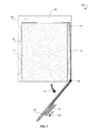
- FIG. 1 is a diagram of an apparatus 100 for removing a modular electronic device from a chassis, in accordance to some example embodiments.
- a chassis 105 defines a chassis enclosure 110 configured to enclose a modular electronic device 115 .
- the modular electronic device 115 is subject to considerable variation and may include one or more of a hard disk drive (HDD), a solid state disk (SSD), a disk array, a compact disk, a flash memory module, and like devices capable of storing data.
- the apparatus 100 may comprise a door 120 pivotally coupled to the chassis 105 in front of the chassis enclosure 110 .
- the door 120 may act as a mechanical attachment point and a guide for a sliding element 125 configured to slidably engage the door 120 and to move in one dimension along the door 120 .
- An arrow 160 shows one of possible directions of moving the sliding element 125 along the door 120 .
- the sliding element 125 may be coupled to an ejection actuator 130 disposed in a rear of the chassis enclosure 110 .
- the sliding element 125 and the ejection actuator 130 may be coupled to each other, either rigidly or flexibly, by means of a linkage element 135 .
- the linkage element 135 may have a first linkage element end and a second linkage element end, and may be connected, by the first linkage element end, to the sliding element 125 .
- Linkage element 135 may be connected to the ejection actuator 130 by the second linkage element end.
- the linkage element 135 may be rigid or flexible.
- the rigid linkage element 135 may be configured as a single element or a multilink element.
- the flexible linkage element 135 may include a fiber, a string, a fishing line, a wire, and the like.
- the linkage element 135 may pass through a point 140 of pivotal coupling of the door 120 to the chassis 105 .
- a length of the door 120 may be variable to regulate a force of ejection of the modular electronic device 115 .
- the apparatus 100 may optionally comprise at least one guide rail 145 to guide the modular electronic device 115 .
- the guide rail 145 may extend from about an opening of the chassis enclosure 110 to the rear of the chassis enclosure 110 .
- the ejection actuator 130 may be configured to move along the chassis enclosure 110 and optionally along the guide rail 145 .
- the ejection actuator 130 may have an angled construction, and in particular, it may be configured as an angle bracket. Due to the angled construction, the ejection actuator 130 may push the modular electronic device 115 while moving along the chassis enclosure 110 in a direction from the rear of the chassis enclosure 110 towards an opening for insertion of the modular electronic device 115 .
- Pushing the modular electronic device 115 will result in decoupling the modular electronic device 115 from a connector 150 in the rear of the chassis enclosure 110 that couples the modular electronic device 115 with the chassis 105 . Furthermore, pushing the modular electronic device 115 will result in moving the modular electronic device 115 along the chassis enclosure 110 in a direction towards the opening and, finally, in removing the modular electronic device 115 from the chassis 105 .
- the door 120 may be configured to rotate around the point 140 between a closed position and an open position.
- An arrow 155 shows one of possible directions of rotation of the door 120 .
- the closed position and the open position of the door 120 are shown in detail with reference to FIGS. 2A and 2B .
- FIGS. 2A and 2B show perspective views 200 , 205 of the apparatus for removing a modular electronic device, in accordance to some example embodiments.
- FIGS. 2A and 2B show an example embodiment with two apparatuses 100 a , 100 b for removing a modular electronic device mounted on top of one another.
- the door 120 of the upper apparatus 100 a on FIGS. 2A and 2B is shown in a closed position. In the closed position, the door 120 may cover the chassis enclosure to capture the modular electronic device mechanically and to prevent the modular electronic device from decoupling and being, for example, accidentally removed from the chassis. Furthermore, the door 120 in the closed position may prevent electromagnetic emissions from the chassis.
- the door 120 of the lower apparatus 100 b on FIGS. 2A and 2B is shown in an open position.
- the door 120 may allow removal of the modular electronic device from the chassis.
- the apparatuses 100 a, 100 b may be configured to accommodate dimensional variations of the modular electronic device.
- spring elements may be mounted, for example, in the rear of the chassis or at any other side of the chassis, to push the modular electronic device against a connector (not shown) coupling the modular electronic device to the chassis.
- Each of the apparatuses 100 a , 100 b may optionally include a locking member 210 configured to lock the door 120 in an engaged position with the chassis.
- the locking member 210 may include a latch or any other suitable type of lock known to those skilled in the art.
- the locking member 210 may prevent unauthorized removal of the modular electronic device from the chassis.
- the locking member 210 may be configured as a tamper evident seal to indicate whether the modular electronic device has been removed from the chassis or reinserted.
- the sliding element 125 of the upper apparatus 100 a on FIGS. 2A and 2B is shown in an initial position of the sliding element 125 . In this position, the sliding element 125 does not extend from the door 120 . In the lower apparatus 100 b on FIGS. 2A and 2B , the sliding element 125 is shown extending from the door 120 (namely, pulled out of the door 120 ).
- the ejection actuator 130 may be configured as an angle bracket and may comprise a pusher 215 to push the modular electronic device. Furthermore, the ejection actuator 130 may comprise a spring member 220 .
- the spring member 220 may have a first spring member end and a second spring member end. The spring member 220 may be connected to the ejection actuator 130 by the first spring member end and to the rear of the chassis by the second spring member end. In view of the connection of the spring member 220 with the chassis, the spring member 220 may be configured to restore the ejection actuator 130 to an initial position of the ejection actuator 130 in the chassis enclosure after the ejection actuator 130 has been moved along the chassis towards an opening for insertion of the modular electronic device.
- the ejection actuator 130 may be mechanized with an electric motor (not shown). Additionally, the ejection actuator 130 may be electronically coupled to at least one sensing means (not shown) configured to alert a user to a complete or an incomplete insertion or a removal of the modular electronic device. The alert may be facilitated by one or more Light Emitting Diodes (LEDs) (not shown) associated with the chassis. Optionally, the alert may be facilitated by a sound generating unit (not shown) associated with the chassis.
- LEDs Light Emitting Diodes
- FIG. 3 shows a diagrammatic representation 300 of assembling an apparatus for removing a modular electronic device from a chassis, in accordance to some example embodiments.
- An example embodiment of assembling two apparatuses for removing a modular electronic device mounted on top of one another is shown in FIG. 3 .
- Assembling an apparatus for removing a modular electronic device from a chassis may start with slidably engaging a sliding element 125 with a door 120 .
- the sliding element 125 may be coupled with the door 120 by means of at least one connecting member 305 .
- the door 120 may have at least one opening 310 .
- the connecting member 305 may be positioned in front of the opening 310 from the side of the door 120 free of the sliding element 125 .
- At least one fastener 315 may go through the connecting member 305 , pass through the opening 310 , and enter into the sliding element 125 , thus enabling the slidable movement of the sliding element 125 along the door 120 .
- the sliding element 125 may be configured so as to be inserted directly into the door 120 . Therefore, no connecting members may be needed for coupling the sliding element 125 with the door 120 .
- Assembling may further continue with pivotal coupling the door 120 , being in slidable engagement with the sliding element 125 , to the chassis (not shown) in front of a chassis enclosure (not shown).
- the pivotal coupling may be performed by means of at least one pivotal axis 320 installed at an opening (not shown) for insertion of a modular electronic device.
- the door 120 may be installed on the axis 320 .
- at least one guide rail 145 may be disposed in the chassis enclosure. The guide rail 145 may guide the modular electronic device in the chassis enclosure.
- an ejection actuator 130 may be disposed in a rear of the chassis enclosure (not shown).
- the ejection actuator 130 may be connected to a first end of a spring member 220 , while the second end may be connected to an axis 325 installed in the rear of the chassis (not shown).
- the ejection actuator 130 may be configured to move along the guide rail 145 .
- the sliding element 125 may be coupled with the ejection actuator 130 by means of a linkage element 135 .
- a first linkage element end may be connected to the sliding element 125
- a second linkage element end may be connected to the ejection actuator 130 .
- the linkage element 135 may be connected to the connecting member 305 connected to the sliding element 125 .
- the linkage element 135 may be connected to the sliding element 125 directly.
- the linkage element 135 may be laid so that the linkage element 135 passes through the axis 320 (i.e., through a point of pivotal coupling the door 120 to the chassis).
- FIG. 4 is a flow chart illustrating a method 400 for assembling an apparatus for removing a modular electronic device from a chassis, in accordance to some example embodiments.
- the method 400 may commence at operation 402 with slidably engaging a sliding element with a door.
- the door may be pivotally coupled to the chassis in front of a chassis enclosure.
- Method 400 may proceed with disposing an ejection actuator in a rear of the chassis enclosure at operation 406 .
- the ejection actuator may be connected to a spring member having a first spring member end and a second spring member end, where the first spring member end may be connected to the ejection actuator, and the second spring member end may be connected to the rear of the chassis at operation 408 .
- a linkage element having a first linkage element end and second linkage element end may be connected, by the first linkage element end, to the sliding element and, by the second linkage element end, to the ejection actuator.
- the linkage element may be laid through a point of pivotal coupling of the door to the chassis at operation 412 .
- a length of the door may be variable to regulate a force of ejection of the modular electronic device.
- the method 400 may optionally proceed with disposing at least one guide rail in the chassis enclosure to guide the modular electronic device.
- the ejection actuator may be electronically coupled to at least one sensing means configured to alert a user to a complete or an incomplete insertion or a removal of the modular electronic device.
- the ejection actuator may be mechanized with an electric motor.
- FIG. 5A shows a diagrammatic representation 500 of an insertion of a modular electronic device 115 into a chassis 105 , in accordance to some example embodiments.
- a door 120 of an apparatus for removing a modular electronic device may be opened, and the modular electronic device 115 may be inserted into an opening of the chassis 105 .
- the modular electronic device 115 may be pushed in a direction towards a rear of the chassis 105 until the modular electronic device 115 is inserted completely into the chassis 105 .
- the door 120 may be rotated around a point of pivotal coupling of the door 120 to the chassis 105 from an open position shown on FIG.
- a locking member (not shown) may be locked to lock the door 120 in an engaged position with the chassis 105 .
- FIG. 5B shows a diagrammatic representation 510 of a removal of a modular electronic device 115 from a chassis 105 , in accordance to some example embodiments.
- a locking member (not shown) may be unlocked to unlock the door 120 from an engaged position with the chassis 105 .
- the door 120 may be rotated around a point of pivotal coupling of the door 120 to the chassis 105 from a closed position to an open position, when the door 120 may allow removal of the modular electronic device 115 from the chassis 105 .
- the door 120 is shown in the open position. After that, the sliding element 125 may be pulled in a direction along the door 120 away from the chassis enclosure.
- Movement of the sliding element 125 coupled with an ejection actuator (not shown) via a linkage element (not shown), may cause movement of the ejection actuator. While moving, the ejection actuator may push the modular electronic device 115 in the chassis enclosure in a direction towards the opening for insertion of the modular electronic device 115 . Pushing the modular electronic device 115 may result in decoupling the modular electronic device 115 from a connector (not shown) in a rear of the chassis enclosure coupling the modular electronic device 115 with the chassis 105 , and moving the modular electronic device 115 along the chassis enclosure in the direction towards the opening for insertion of the modular electronic device 115 .
- the modular electronic device 115 When the modular electronic device 115 extends out from the chassis 105 for a length enough to take the modular electronic device 115 , the modular electronic device 115 may be taken and removed from the chassis 105 . After the ejection of the modular electronic device 115 , the sliding element 125 may be released. After releasing the sliding element 125 , in view of connection of the ejection actuator to a spring member (not shown) connected by one end of the spring member to the rear of the chassis 105 , the spring member may enable restoration of the ejection actuator to an initial position in the chassis enclosure.
- FIG. 6 is a flow chart illustrating a method 600 for using an apparatus for removing a modular electronic device from a chassis, in accordance to some example embodiments.
- the method 600 may optionally commence with moving a locking member in slidable engagement with a door to unlock the door from an engaged position with the chassis at operation 602 .
- the door may be rotated around a point of pivotal coupling of the door to the chassis to an open position, when the door allows removal of the modular electronic device from the chassis.
- the method 600 may proceed with operation 606 of sliding the sliding element along the door in a direction away from the chassis enclosure (i.e., pulling the sliding element in a direction towards a person who is removing the modular electronic device).
- a force of ejection of the modular electronic device may be optionally regulated by regulating a force of pulling the sliding element along the door.
- the higher the force of pulling the sliding element the higher the force of ejection of the modular electronic device from the chassis.
- Pulling the sliding element coupled with an ejection actuator by means of a linkage element, may cause movement of the ejection actuator along the chassis in a direction towards the opening for insertion of the modular electronic device.
- the ejection actuator while moving, may push the modular electronic device in a direction of movement of the ejection actuator resulting in decoupling the modular electronic device from the chassis and ejection of the modular electronic device from the chassis.
- the sliding element may be released. Releasing the sliding element may result in restoring the ejection actuator to an initial position of the ejection actuator in the chassis enclosure by means of a spring member connected to the ejection actuator and the rear of the chassis.
Landscapes
- Engineering & Computer Science (AREA)
- Theoretical Computer Science (AREA)
- Computer Hardware Design (AREA)
- Power Engineering (AREA)
- Human Computer Interaction (AREA)
- Physics & Mathematics (AREA)
- General Engineering & Computer Science (AREA)
- General Physics & Mathematics (AREA)
- Microelectronics & Electronic Packaging (AREA)
- Casings For Electric Apparatus (AREA)
- Mounting Of Printed Circuit Boards And The Like (AREA)
- Manufacturing & Machinery (AREA)
Abstract
Description
Claims (20)
Priority Applications (4)
| Application Number | Priority Date | Filing Date | Title |
|---|---|---|---|
| US13/939,027 US8991950B2 (en) | 2013-07-10 | 2013-07-10 | Modular electronics chassis |
| PCT/US2014/045824 WO2015006373A1 (en) | 2013-07-10 | 2014-07-08 | Modular electronics chassis |
| JP2016525438A JP2016525796A (en) | 2013-07-10 | 2014-07-08 | Modular electronics chassis |
| EP14823501.3A EP3020259A4 (en) | 2013-07-10 | 2014-07-08 | Modular electronics chassis |
Applications Claiming Priority (1)
| Application Number | Priority Date | Filing Date | Title |
|---|---|---|---|
| US13/939,027 US8991950B2 (en) | 2013-07-10 | 2013-07-10 | Modular electronics chassis |
Publications (2)
| Publication Number | Publication Date |
|---|---|
| US20150015131A1 US20150015131A1 (en) | 2015-01-15 |
| US8991950B2 true US8991950B2 (en) | 2015-03-31 |
Family
ID=52276572
Family Applications (1)
| Application Number | Title | Priority Date | Filing Date |
|---|---|---|---|
| US13/939,027 Active 2033-08-22 US8991950B2 (en) | 2013-07-10 | 2013-07-10 | Modular electronics chassis |
Country Status (4)
| Country | Link |
|---|---|
| US (1) | US8991950B2 (en) |
| EP (1) | EP3020259A4 (en) |
| JP (1) | JP2016525796A (en) |
| WO (1) | WO2015006373A1 (en) |
Cited By (8)
| Publication number | Priority date | Publication date | Assignee | Title |
|---|---|---|---|---|
| US20150286021A1 (en) * | 2007-01-19 | 2015-10-08 | Adc Telecommunications, Inc. | Adapter panel with lateral sliding adapter arrays |
| USD750033S1 (en) * | 2013-07-10 | 2016-02-23 | Exablox Corporation | Modular electronics chassis |
| US9389651B2 (en) | 2013-05-22 | 2016-07-12 | Exablox Corporation | Modular electronics chassis |
| US9638880B2 (en) | 2007-01-19 | 2017-05-02 | Commscope Technologies Llc | Adapter panel with lateral sliding adapter arrays |
| US9992904B2 (en) * | 2015-09-24 | 2018-06-05 | Quanta Computer Inc. | Electronic device enclosure with an access mechanism |
| US10126786B2 (en) * | 2015-07-30 | 2018-11-13 | Western Digital Technologies, Inc. | Ejection mechanism assembly for storage drive and storage drive having the ejection mechanism assembly |
| US10692541B2 (en) | 2018-06-14 | 2020-06-23 | Seagate Technology Llc | Carrierless drive insertion, retention and removal system |
| US11567281B2 (en) | 2013-09-23 | 2023-01-31 | Commscope Connectivity Uk Limited | Telecommunications chassis |
Families Citing this family (17)
| Publication number | Priority date | Publication date | Assignee | Title |
|---|---|---|---|---|
| US9628438B2 (en) | 2012-04-06 | 2017-04-18 | Exablox | Consistent ring namespaces facilitating data storage and organization in network infrastructures |
| US9552382B2 (en) | 2013-04-23 | 2017-01-24 | Exablox Corporation | Reference counter integrity checking |
| US9514137B2 (en) | 2013-06-12 | 2016-12-06 | Exablox Corporation | Hybrid garbage collection |
| JP2016526720A (en) | 2013-06-19 | 2016-09-05 | エグザブロックス・コーポレーション | Data scrubbing in cluster-based storage systems |
| US9934242B2 (en) | 2013-07-10 | 2018-04-03 | Exablox Corporation | Replication of data between mirrored data sites |
| US10248556B2 (en) | 2013-10-16 | 2019-04-02 | Exablox Corporation | Forward-only paged data storage management where virtual cursor moves in only one direction from header of a session to data field of the session |
| US9985829B2 (en) | 2013-12-12 | 2018-05-29 | Exablox Corporation | Management and provisioning of cloud connected devices |
| US9774582B2 (en) | 2014-02-03 | 2017-09-26 | Exablox Corporation | Private cloud connected device cluster architecture |
| JP2017504924A (en) | 2014-02-04 | 2017-02-09 | エグザブロックス・コーポレーション | Content-based organization of the file system |
| US10474654B2 (en) | 2015-08-26 | 2019-11-12 | Storagecraft Technology Corporation | Structural data transfer over a network |
| DE102016100237B4 (en) | 2016-01-08 | 2022-03-31 | Omron Corporation | Storage medium recording device, industrial computer and method |
| US9846553B2 (en) | 2016-05-04 | 2017-12-19 | Exablox Corporation | Organization and management of key-value stores |
| US10405453B1 (en) * | 2018-06-07 | 2019-09-03 | Dell Products L.P. | Systems and methods for carrier-less storage device extraction in an information handling system |
| CN111208875B (en) * | 2018-11-21 | 2023-10-03 | 英业达科技有限公司 | Server device |
| CN113835494B (en) * | 2020-06-24 | 2024-02-13 | 戴尔产品有限公司 | Single-blade air damper for rack chassis |
| CN112037826B (en) * | 2020-09-27 | 2024-08-06 | 记忆科技(深圳)有限公司 | Structure convenient for hard disk maintenance and hard disk maintenance method |
| US12439544B2 (en) * | 2022-04-20 | 2025-10-07 | Pure Storage, Inc. | Retractable pivoting trap door |
Citations (16)
| Publication number | Priority date | Publication date | Assignee | Title |
|---|---|---|---|---|
| US5483419A (en) * | 1991-09-24 | 1996-01-09 | Teac Corporation | Hot-swappable multi-cartridge docking module |
| US5597316A (en) * | 1994-12-07 | 1997-01-28 | Berg Technology, Inc. | Memory card connector having improved eject mechanism and method of use |
| US6210188B1 (en) * | 1998-12-24 | 2001-04-03 | Hon Hai Precision Ind. Co., Ltd. | Electrical card connector having a card ejection mechanism |
| US6270174B1 (en) * | 1999-07-05 | 2001-08-07 | Fujitsu Limited | Case for electronic equipment |
| US6411505B1 (en) * | 1999-11-12 | 2002-06-25 | Apple Computer, Inc. | Computer housing for a portable computer |
| US6587350B1 (en) * | 2002-05-16 | 2003-07-01 | Inventec Corporation | Ejection mechanism for modular electronic element |
| US6798650B2 (en) * | 1997-08-04 | 2004-09-28 | Sun Microsystems, Inc. | Disk drive bracket |
| US20050030721A1 (en) * | 2002-08-09 | 2005-02-10 | Tsutomu Shimada | Electronic apparatus and information processing apparatus |
| US7559781B2 (en) * | 2006-09-18 | 2009-07-14 | Datastore Technology Co., Ltd. | Disk-mounting assembly for mounting removably a disk drive in an electronic device |
| US7559782B2 (en) * | 2006-10-20 | 2009-07-14 | Datastore Technology Co., Ltd. | Storage device box |
| US8045326B1 (en) * | 2004-07-01 | 2011-10-25 | Oracle America Inc. | Hard disk drive bracket |
| US20110299237A1 (en) * | 2010-06-03 | 2011-12-08 | Wen-Peng Liang | Multi-level hard drive enclosure |
| US8077467B2 (en) * | 2009-01-05 | 2011-12-13 | Hong Fu Jin Precision Industry (Shenzhen) Co., Ltd. | Mounting apparatus for disk drive |
| US20120218705A1 (en) * | 2011-02-25 | 2012-08-30 | Jui-Shu Huang | Removable hard disk drive bay |
| US8355256B2 (en) * | 2009-08-28 | 2013-01-15 | Hong Fu Jin Precision Industry (Shenzhen) Co., Ltd. | Mounting apparatus for data storage device |
| US20140345105A1 (en) * | 2013-05-22 | 2014-11-27 | Exablox Corporation | Modular Electronics Chassis |
Family Cites Families (9)
| Publication number | Priority date | Publication date | Assignee | Title |
|---|---|---|---|---|
| US5262918A (en) * | 1991-06-28 | 1993-11-16 | Syquest Technology, Inc. | Removable cartridge with a 2.5 inch form factor and an interlocking mechanism adapted for use in a disk drive |
| JPH096932A (en) * | 1995-06-21 | 1997-01-10 | Berg Technol Inc | Ejecting device |
| US5757617A (en) * | 1996-08-19 | 1998-05-26 | Sherry; Raymond C. | Module with snap-fit cover |
| JPH10320882A (en) * | 1997-05-22 | 1998-12-04 | Onkyo Corp | Door opening and closing mechanism in recording / reproducing device |
| US20020008932A1 (en) * | 1998-01-20 | 2002-01-24 | Brent R. Bateman | Gateway actuator |
| JP2000106248A (en) * | 1998-09-30 | 2000-04-11 | Fujitsu General Ltd | Eject device for information storage unit |
| US6134116A (en) * | 1999-04-27 | 2000-10-17 | Dell Usa, L. P. | Apparatus and method for latching a door in a computer system |
| US8215727B2 (en) * | 2007-04-13 | 2012-07-10 | Drobo, Inc. | Carrierless storage system enclosure with ejection mechanism |
| JP5267414B2 (en) * | 2009-10-09 | 2013-08-21 | 富士通株式会社 | Electronics |
-
2013
- 2013-07-10 US US13/939,027 patent/US8991950B2/en active Active
-
2014
- 2014-07-08 JP JP2016525438A patent/JP2016525796A/en active Pending
- 2014-07-08 WO PCT/US2014/045824 patent/WO2015006373A1/en not_active Ceased
- 2014-07-08 EP EP14823501.3A patent/EP3020259A4/en not_active Withdrawn
Patent Citations (17)
| Publication number | Priority date | Publication date | Assignee | Title |
|---|---|---|---|---|
| US5483419A (en) * | 1991-09-24 | 1996-01-09 | Teac Corporation | Hot-swappable multi-cartridge docking module |
| US5597316A (en) * | 1994-12-07 | 1997-01-28 | Berg Technology, Inc. | Memory card connector having improved eject mechanism and method of use |
| US6798650B2 (en) * | 1997-08-04 | 2004-09-28 | Sun Microsystems, Inc. | Disk drive bracket |
| US6210188B1 (en) * | 1998-12-24 | 2001-04-03 | Hon Hai Precision Ind. Co., Ltd. | Electrical card connector having a card ejection mechanism |
| US6270174B1 (en) * | 1999-07-05 | 2001-08-07 | Fujitsu Limited | Case for electronic equipment |
| US6411505B1 (en) * | 1999-11-12 | 2002-06-25 | Apple Computer, Inc. | Computer housing for a portable computer |
| US6587350B1 (en) * | 2002-05-16 | 2003-07-01 | Inventec Corporation | Ejection mechanism for modular electronic element |
| US20050030721A1 (en) * | 2002-08-09 | 2005-02-10 | Tsutomu Shimada | Electronic apparatus and information processing apparatus |
| US8045326B1 (en) * | 2004-07-01 | 2011-10-25 | Oracle America Inc. | Hard disk drive bracket |
| US7559781B2 (en) * | 2006-09-18 | 2009-07-14 | Datastore Technology Co., Ltd. | Disk-mounting assembly for mounting removably a disk drive in an electronic device |
| US7559782B2 (en) * | 2006-10-20 | 2009-07-14 | Datastore Technology Co., Ltd. | Storage device box |
| US8077467B2 (en) * | 2009-01-05 | 2011-12-13 | Hong Fu Jin Precision Industry (Shenzhen) Co., Ltd. | Mounting apparatus for disk drive |
| US8355256B2 (en) * | 2009-08-28 | 2013-01-15 | Hong Fu Jin Precision Industry (Shenzhen) Co., Ltd. | Mounting apparatus for data storage device |
| US20110299237A1 (en) * | 2010-06-03 | 2011-12-08 | Wen-Peng Liang | Multi-level hard drive enclosure |
| US20120218705A1 (en) * | 2011-02-25 | 2012-08-30 | Jui-Shu Huang | Removable hard disk drive bay |
| US8369080B2 (en) * | 2011-02-25 | 2013-02-05 | Jui-Shu Huang | Removable hard disk drive bay |
| US20140345105A1 (en) * | 2013-05-22 | 2014-11-27 | Exablox Corporation | Modular Electronics Chassis |
Cited By (33)
| Publication number | Priority date | Publication date | Assignee | Title |
|---|---|---|---|---|
| US11269150B2 (en) | 2007-01-19 | 2022-03-08 | Commscope Technologies Llc | Adapter panel with lateral sliding adapter arrays |
| US10203464B1 (en) | 2007-01-19 | 2019-02-12 | Commscope Technologies Llc | Adapter panel with lateral sliding adapter arrays |
| US12164168B2 (en) | 2007-01-19 | 2024-12-10 | Commscope Technologies Llc | Adapter panel with lateral sliding adapter arrays |
| US9435974B2 (en) | 2007-01-19 | 2016-09-06 | Commscope Technologies Llc | Adapter panel with lateral sliding adapter arrays |
| US9435976B2 (en) | 2007-01-19 | 2016-09-06 | Commscope Technologies Llc | Adapter panel with lateral sliding adapter arrays |
| US9448379B2 (en) | 2007-01-19 | 2016-09-20 | Commscope Technologies Llc | Adapter panel with lateral sliding adapter arrays |
| US9448378B2 (en) * | 2007-01-19 | 2016-09-20 | Commscope Technologies Llc | Adapter panel with lateral sliding adapter arrays |
| US9488796B2 (en) | 2007-01-19 | 2016-11-08 | Commscope Technologies Llc | Adapter panel with lateral sliding adapter arrays |
| US9638880B2 (en) | 2007-01-19 | 2017-05-02 | Commscope Technologies Llc | Adapter panel with lateral sliding adapter arrays |
| US9638879B2 (en) | 2007-01-19 | 2017-05-02 | Commscope Technologies Llc | Adapter panel with lateral sliding adapter arrays |
| US9645342B2 (en) | 2007-01-19 | 2017-05-09 | Commscope Technologies Llc | Adapter panel with lateral sliding adapter arrays |
| US9690066B2 (en) | 2007-01-19 | 2017-06-27 | Commscope Technologies Llc | Adapter panel with lateral sliding adapter arrays |
| US9703059B2 (en) | 2007-01-19 | 2017-07-11 | Commscope Technologies Llc | Adapter panel with lateral sliding adapter arrays |
| US9709764B2 (en) | 2007-01-19 | 2017-07-18 | Commscope Technologies Llc | Adapter panel with lateral sliding adapter arrays |
| US12111507B2 (en) | 2007-01-19 | 2024-10-08 | Commscope Technologies Llc | Adapter panel with lateral sliding adapter arrays |
| US9995897B2 (en) | 2007-01-19 | 2018-06-12 | Commscope Technologies Llc | Adapter panel with lateral sliding adapter arrays |
| US11789225B2 (en) | 2007-01-19 | 2023-10-17 | Commscope Technologies Llc | Adapter panel with lateral sliding adapter arrays |
| US10310204B2 (en) | 2007-01-19 | 2019-06-04 | Commscope Technologies Llc | Adapter panel with lateral sliding adapter arrays |
| US11333840B2 (en) | 2007-01-19 | 2022-05-17 | Commscope Technologies Llc | Adapter panel with lateral sliding adapter arrays |
| US10473874B2 (en) | 2007-01-19 | 2019-11-12 | Commscope Technologies Llc | Adapter panel with lateral sliding adapter arrays |
| US11314028B2 (en) | 2007-01-19 | 2022-04-26 | Commscope Technologies Llc | Adapter panel with lateral sliding adapter arrays |
| US10739544B2 (en) | 2007-01-19 | 2020-08-11 | Commscope Technologies Llc | Adapter panel with lateral sliding adapter arrays |
| US10969553B2 (en) | 2007-01-19 | 2021-04-06 | Commscope Technologies Llc | Adapter panel with lateral sliding adapter arrays |
| US11262517B2 (en) | 2007-01-19 | 2022-03-01 | Commscope Technologies Llc | Adapter panel with lateral sliding adapter arrays |
| US20150286021A1 (en) * | 2007-01-19 | 2015-10-08 | Adc Telecommunications, Inc. | Adapter panel with lateral sliding adapter arrays |
| US11300747B2 (en) | 2007-01-19 | 2022-04-12 | Commscope Technologies Llc | Adapter panel with lateral sliding adapter arrays |
| US9389651B2 (en) | 2013-05-22 | 2016-07-12 | Exablox Corporation | Modular electronics chassis |
| USD750033S1 (en) * | 2013-07-10 | 2016-02-23 | Exablox Corporation | Modular electronics chassis |
| US11567281B2 (en) | 2013-09-23 | 2023-01-31 | Commscope Connectivity Uk Limited | Telecommunications chassis |
| US12025846B2 (en) | 2013-09-23 | 2024-07-02 | Commscope Connectivity Uk Limited | Telecommunications chassis |
| US10126786B2 (en) * | 2015-07-30 | 2018-11-13 | Western Digital Technologies, Inc. | Ejection mechanism assembly for storage drive and storage drive having the ejection mechanism assembly |
| US9992904B2 (en) * | 2015-09-24 | 2018-06-05 | Quanta Computer Inc. | Electronic device enclosure with an access mechanism |
| US10692541B2 (en) | 2018-06-14 | 2020-06-23 | Seagate Technology Llc | Carrierless drive insertion, retention and removal system |
Also Published As
| Publication number | Publication date |
|---|---|
| EP3020259A4 (en) | 2017-03-29 |
| WO2015006373A1 (en) | 2015-01-15 |
| JP2016525796A (en) | 2016-08-25 |
| US20150015131A1 (en) | 2015-01-15 |
| EP3020259A1 (en) | 2016-05-18 |
Similar Documents
| Publication | Publication Date | Title |
|---|---|---|
| US8991950B2 (en) | Modular electronics chassis | |
| US9389651B2 (en) | Modular electronics chassis | |
| US8023263B2 (en) | Latch for securing a hardware component into a component bay | |
| US7379294B2 (en) | Quick plug/eject concept SATA hard disk drive rack | |
| US8498120B2 (en) | Locking structure for draw-type electronic device | |
| US5269698A (en) | Retaining and release mechanism for computer storage devices including a pawl latch assembly | |
| US10368460B1 (en) | Sliding apparatus, server casing, and electronic device using the same | |
| US10667424B2 (en) | Sliding apparatus and server casing using the same | |
| US20120300384A1 (en) | Mechanical conversion sleeve | |
| US20160353600A1 (en) | Carrier used for mounting data storage drive into enclosure | |
| US20110139735A1 (en) | Retaining apparatus for data storage device | |
| US20080239651A1 (en) | Tool-less electronic component retention | |
| US10936024B2 (en) | Storage drive carrier for high-density storage solution | |
| WO2017063436A1 (en) | Subrack locking mechanism and power supply cabinet | |
| TWM556462U (en) | Positioning module of open-type screwless access device | |
| US8817463B1 (en) | Electronics rack with a movable power distribution unit | |
| CN104620687A (en) | Electronic device including retractable bolt member | |
| US20130180935A1 (en) | Apparatus for storing solid state drives or hard disk drives | |
| US10080307B2 (en) | Server rack | |
| CN104024900B (en) | There is the connector modules of movable optical connector | |
| US20160252935A1 (en) | Locking bar for a computer | |
| TW201630515A (en) | Latching system | |
| CN115309238A (en) | Functional module locking device and functional module | |
| CN203502887U (en) | Quick release structure of the chassis memory access device | |
| JP6013134B2 (en) | Opening and closing mechanism |
Legal Events
| Date | Code | Title | Description |
|---|---|---|---|
| AS | Assignment |
Owner name: EXABLOX CORPORATION, CALIFORNIA Free format text: ASSIGNMENT OF ASSIGNORS INTEREST;ASSIGNORS:PRIVITERA, PETER;CARVER, JON;DRUKER, JOSHUA;AND OTHERS;SIGNING DATES FROM 20130617 TO 20130709;REEL/FRAME:030973/0861 |
|
| STCF | Information on status: patent grant |
Free format text: PATENTED CASE |
|
| AS | Assignment |
Owner name: SILICON VALLEY BANK, AS ADMINISTRATIVE AGENT, CALI Free format text: SECURITY INTEREST;ASSIGNORS:EXABLOX CORPORATION;STORAGECRAFT INTERMEDIATE HOLDINGS, INC.;STORAGECRAFT ACQUISITION CORPORATION;AND OTHERS;REEL/FRAME:041748/0849 Effective date: 20170324 |
|
| MAFP | Maintenance fee payment |
Free format text: PAYMENT OF MAINTENANCE FEE, 4TH YR, SMALL ENTITY (ORIGINAL EVENT CODE: M2551); ENTITY STATUS OF PATENT OWNER: SMALL ENTITY Year of fee payment: 4 |
|
| FEPP | Fee payment procedure |
Free format text: ENTITY STATUS SET TO UNDISCOUNTED (ORIGINAL EVENT CODE: BIG.); ENTITY STATUS OF PATENT OWNER: SMALL ENTITY |
|
| FEPP | Fee payment procedure |
Free format text: ENTITY STATUS SET TO UNDISCOUNTED (ORIGINAL EVENT CODE: BIG.); ENTITY STATUS OF PATENT OWNER: LARGE ENTITY |
|
| AS | Assignment |
Owner name: MONROE CAPITAL MANAGEMENT ADVISORS, LLC, AS COLLATERAL AGENT, ILLINOIS Free format text: SECURITY INTEREST;ASSIGNORS:ARCSERVE (USA) LLC;STORAGECRAFT TECHNOLOGY LLC;ZETTA, LLC;REEL/FRAME:055603/0219 Effective date: 20210316 Owner name: STORAGECRAFT TECHNOLOGY CORPORATION, MINNESOTA Free format text: TERMINATION AND RELEASE OF PATENT SECURITY AGREEMENT;ASSIGNOR:SILICON VALLEY BANK, AS ADMINISTRATIVE AGENT;REEL/FRAME:055614/0852 Effective date: 20210316 Owner name: EXABLOX CORPORATION, MINNESOTA Free format text: TERMINATION AND RELEASE OF PATENT SECURITY AGREEMENT;ASSIGNOR:SILICON VALLEY BANK, AS ADMINISTRATIVE AGENT;REEL/FRAME:055614/0852 Effective date: 20210316 Owner name: STORAGECRAFT ACQUISITION CORPORATION, MINNESOTA Free format text: TERMINATION AND RELEASE OF PATENT SECURITY AGREEMENT;ASSIGNOR:SILICON VALLEY BANK, AS ADMINISTRATIVE AGENT;REEL/FRAME:055614/0852 Effective date: 20210316 Owner name: STORAGECRAFT INTERMEDIATE HOLDINGS, INC., MINNESOTA Free format text: TERMINATION AND RELEASE OF PATENT SECURITY AGREEMENT;ASSIGNOR:SILICON VALLEY BANK, AS ADMINISTRATIVE AGENT;REEL/FRAME:055614/0852 Effective date: 20210316 |
|
| MAFP | Maintenance fee payment |
Free format text: PAYMENT OF MAINTENANCE FEE, 8TH YEAR, LARGE ENTITY (ORIGINAL EVENT CODE: M1552); ENTITY STATUS OF PATENT OWNER: LARGE ENTITY Year of fee payment: 8 |
|
| AS | Assignment |
Owner name: STORAGECRAFT, LLC, MINNESOTA Free format text: ASSIGNMENT OF ASSIGNORS INTEREST;ASSIGNORS:MONROE CAPITAL MANAGEMENT ADVISORS, LLC;ARCSTOR MIDCO LLC;ARCSERVE ACQUISITION COMPANY LLC;AND OTHERS;REEL/FRAME:068660/0208 Effective date: 20240102 Owner name: STORAGECRAFT TECHNOLOGY LLC, UTAH Free format text: CHANGE OF NAME;ASSIGNOR:STORAGECRAFT TECHNOLOGY CORPORATION;REEL/FRAME:068660/0176 Effective date: 20210315 |