US8991101B2 - Door entryway system - Google Patents
Door entryway system Download PDFInfo
- Publication number
- US8991101B2 US8991101B2 US14/013,675 US201314013675A US8991101B2 US 8991101 B2 US8991101 B2 US 8991101B2 US 201314013675 A US201314013675 A US 201314013675A US 8991101 B2 US8991101 B2 US 8991101B2
- Authority
- US
- United States
- Prior art keywords
- door
- threshold
- top portion
- wall
- cap
- Prior art date
- Legal status (The legal status is an assumption and is not a legal conclusion. Google has not performed a legal analysis and makes no representation as to the accuracy of the status listed.)
- Active, expires
Links
Images


Classifications
-
- E—FIXED CONSTRUCTIONS
- E06—DOORS, WINDOWS, SHUTTERS, OR ROLLER BLINDS IN GENERAL; LADDERS
- E06B—FIXED OR MOVABLE CLOSURES FOR OPENINGS IN BUILDINGS, VEHICLES, FENCES OR LIKE ENCLOSURES IN GENERAL, e.g. DOORS, WINDOWS, BLINDS, GATES
- E06B7/00—Special arrangements or measures in connection with doors or windows
- E06B7/14—Measures for draining-off condensed water or water leaking-in frame members for draining off condensation water, throats at the bottom of a sash
-
- E—FIXED CONSTRUCTIONS
- E06—DOORS, WINDOWS, SHUTTERS, OR ROLLER BLINDS IN GENERAL; LADDERS
- E06B—FIXED OR MOVABLE CLOSURES FOR OPENINGS IN BUILDINGS, VEHICLES, FENCES OR LIKE ENCLOSURES IN GENERAL, e.g. DOORS, WINDOWS, BLINDS, GATES
- E06B1/00—Border constructions of openings in walls, floors, or ceilings; Frames to be rigidly mounted in such openings
- E06B1/70—Sills; Thresholds
-
- E—FIXED CONSTRUCTIONS
- E06—DOORS, WINDOWS, SHUTTERS, OR ROLLER BLINDS IN GENERAL; LADDERS
- E06B—FIXED OR MOVABLE CLOSURES FOR OPENINGS IN BUILDINGS, VEHICLES, FENCES OR LIKE ENCLOSURES IN GENERAL, e.g. DOORS, WINDOWS, BLINDS, GATES
- E06B7/00—Special arrangements or measures in connection with doors or windows
- E06B7/16—Sealing arrangements on wings or parts co-operating with the wings
- E06B7/22—Sealing arrangements on wings or parts co-operating with the wings by means of elastic edgings, e.g. elastic rubber tubes; by means of resilient edgings, e.g. felt or plush strips, resilient metal strips
- E06B7/23—Plastic, sponge rubber, or like strips or tubes
- E06B7/2316—Plastic, sponge rubber, or like strips or tubes used as a seal between the floor and the wing
-
- E—FIXED CONSTRUCTIONS
- E06—DOORS, WINDOWS, SHUTTERS, OR ROLLER BLINDS IN GENERAL; LADDERS
- E06B—FIXED OR MOVABLE CLOSURES FOR OPENINGS IN BUILDINGS, VEHICLES, FENCES OR LIKE ENCLOSURES IN GENERAL, e.g. DOORS, WINDOWS, BLINDS, GATES
- E06B1/00—Border constructions of openings in walls, floors, or ceilings; Frames to be rigidly mounted in such openings
- E06B1/70—Sills; Thresholds
- E06B2001/707—Thresholds with special provision for insulation
Definitions
- the present disclosure relates generally to entryway systems for residential and commercial buildings and more particularly to threshold assemblies of entryway systems.
- Entryway systems used in building construction generally include a pair of vertically extending door jambs and a head jamb that frame the entryway and receive a hinged door panel.
- An elongated threshold assembly is attached at its ends to the bottoms of the door jambs and spans the bottom of the entryway.
- Many modern threshold assemblies include a frame defining an upwardly open channel from which a sill slopes outwardly and downwardly.
- a threshold cap is disposed in the upwardly open channel and underlies a closed door mounted in the entryway.
- the threshold cap usually is manually adjustable (using, for example, screw mechanisms) in a vertical direction to engage and form a seal with the bottom of the door panel or a flexible sweep attached thereto.
- threshold assemblies include an upstanding dam that forms the upper part of the outside channel wall. It is also common where plastic threshold caps are used to form the threshold cap with an overlapping tongue along its outside edge that overlaps the dam to prevent leakage of rainwater from the top of the threshold cap directly into the gap between the forward edge of the cap and its channel.
- an entryway system that includes a door entryway system and threshold assembly that improves management of water, both incidental and non-incidental, entering the threshold assembly.
- a door entryway system can include a door sweep capable of attachment to a bottom of a door panel.
- the door entryway system can also include a threshold assembly having a self-articulating threshold cap configured to self-adjust toward the door sweep and interact therewith to form a sealing barrier when the door panel is in a closed position.
- the door entryway system can also include a threshold assembly that can be configured to sealingly interact with the door sweep.
- the threshold assembly can include a threshold substrate having a nosing defining one side of an open-ended sill channel. Also included in the threshold assembly is a self-articulating threshold cap that can be received within the open-ended sill channel.
- the self-articulating threshold cap can be configured to self-adjust toward the door sweep and interact therewith to form a sealing barrier when the door panel is in a closed position.
- a nosing strip also can be secured to the nosing and configured to sealingly engage the self-articulating threshold cap.
- An additional embodiment of a door entryway system can include a door sweep capable of being attached to a bottom of a door panel and a threshold assembly configured to sealingly interact with the door sweep.
- the threshold assembly can include a threshold substrate defining an open-ended sill channel, and further comprising a threshold cap disposed within the sill channel.
- the threshold assembly can also include a self-articulating means for maintaining a sealing barrier between the door sweep and the threshold cap when the door panel is in a closed position.
- the threshold assembly can include a threshold substrate having a forward end adapted to be disposed exterior to a building structure.
- the forward end can include at least one drain hole configured to allow water to exit the threshold substrate.
- the threshold assembly can include at least one air inlet configured to allow air to enter the threshold substrate.
- the air inlet can be separate from the drain hole. Further, the air inlet can be in an elevated arrangement with respect to the drain hole such that water exits the threshold substrate through the at least one drain hole.
- the forward end of the threshold substrate can optionally include a forward edge with the drain hole and the air inlet can be at least partially defined by the forward edge.
- the forward edge of the threshold substrate can optionally define a pair of drain holes positioned at opposing ends thereof.
- a plurality of the air inlets can be disposed between the pair of drain holes along the forward edge.
- the forward edge can define a recess forming the one or more air inlets.
- the forward edge can optionally include a wall extending substantially perpendicular to a floor of the threshold substrate.
- the forward edge can optionally include a lip extending substantially perpendicular from the wall. The forward edge can define a recess extending from the wall and about the lip to form an air inlet.
- a decking cover plate configured to extend about the threshold substrate to form an upper surface thereof.
- the decking cover plate can extend about the lip so as to cooperate with the forward edge to form the at least one air inlet.
- the forward edge can include a top surface defining a recess.
- the decking cover plate can extend about the threshold substrate to form an upper surface thereof.
- the optionally decking cover plate can be in abutting contact with the top surface of the forward edge to enclose the recess so as to cooperate therewith to form the at least one air inlet.
- the threshold substrate is constructed from an injection molded plastic material. Other materials can be used to form the threshold substrate.
- An additional, second embodiment of a threshold assembly for a door entryway system can include a threshold substrate having a nosing defining one side of an open-ended sill channel.
- the threshold substrate can also include a self-articulating threshold cap received within the open-ended sill channel.
- the self-articulating threshold cap can be configured to self-adjust toward one of a door panel and a door sweep and being capable of interacting therewith so as to form a sealing barrier therebetween when the door panel is in a closed position.
- a nosing strip can be secured to the nosing and is configured to sealingly engage the self-articulating threshold cap.
- the nosing strip can include a resilient fin configured to sealingly engage the self-articulating threshold cap.
- the self-articulating threshold cap can optionally include a top articulating portion having a top wall and a locking wall extending substantially perpendicularly from the top wall.
- the resilient fin can interact with the locking wall to form a sealing barrier along a length of the threshold substrate.
- the self-articulating threshold cap can further optionally include a bottom support wall disposed adjacent to a floor of the sill channel.
- the self-articulating threshold cap can have a rear wall operably engaged with and extending substantially perpendicularly from the bottom support wall so as to be substantially parallel with an inside surface of the nosing. Further, the rear wall can have a projection configured to interact with the nosing strip to form a sealing barrier.
- a biasing mechanism configured to interact with the threshold cap and to bias the threshold cap against the door sweep when the door panel is in the closed position.
- the biasing mechanism can be disposed within a cavity defined by the threshold cap.
- the threshold cap can optionally include an articulating top portion capable of being deflected by the door panel or door sweep when the door panel is moved toward the closed position.
- the articulating top portion of the threshold cap is capable of biasing toward the door panel or the door sweep when the door panel is in the closed position.
- the threshold cap is optionally an integrally-formed and unitary workpiece constructed from, for example, a polymer material.
- the threshold cap can include a bottom support wall capable of engaging a floor of the sill channel, a front wall operably engaged with the bottom support wall, an articulating top portion extending from the front wall, a rear wall operably engaged with the bottom support wall, and an intermediate wall extending from the bottom support wall.
- the top articulating portion can include a top wall and a locking wall extending substantially perpendicularly from the top wall.
- the locking wall can extend between the rear wall and intermediate wall.
- the locking wall can have a hook portion configured to interact with the intermediate wall to prevent the locking wall from entirely advancing therepast.
- the threshold substrate is optionally constructed from an injection molded plastic material.
- the threshold cap capable of being received within a sill channel of a threshold assembly for a door entryway.
- the threshold cap can include a bottom support wall capable of engaging a floor of the sill channel.
- a front wall can be operably engaged with the bottom support wall and has at least a portion thereof being substantially perpendicular to the bottom support wall.
- the threshold cap can also include an articulating top portion extending from the front wall. The articulating top portion can be configured to bias against one of a door sweep mounted to a door panel when the door panel is in a closed position.
- a rear wall operably engaged with and extending substantially perpendicularly from the bottom support wall so as to be substantially parallel with the front wall.
- the rear wall optionally includes a longitudinally extending projection configured to interact with the threshold assembly to form a sealing barrier along the sill channel.
- top articulating portion optionally included on the top articulating portion is a top wall and a locking wall extending substantially perpendicularly from the top wall.
- an intermediate wall having a first leg and a second leg.
- the first leg can extend perpendicularly from the bottom support wall and the second leg can depend perpendicularly from the first leg toward the rear wall.
- the locking wall can extend between the rear wall and the second leg and can have a hook portion configured to interact with the second leg to prevent the locking wall from advancing entirely therepast.
- a biasing mechanism adapted to bias the top portion toward the one or both of the door panel and the door sweep assembly. Such biasing allows sealing contact therewith when the door panel is in the closed position.
- the biasing mechanism can be disposed within a cavity at least partially defined by the bottom support wall, the front wall and the articulating top portion.
- the threshold cap can optionally be an integrally-formed and unitary workpiece constructed from a polymer material.
- the front wall includes a cap leg capable of being received within a spacer of the threshold assembly.
- An additional embodiment of the invention is a door sweep for a door entryway system.
- the door sweep can include a support wall capable of attachment to a bottom of a door panel.
- the support wall can have a first edge and a second edge.
- the door sweep can also include a resilient sealing provision disposed at the first edge of the support wall.
- the resilient sealing provision is capable of sealingly engaging a self-articulating threshold cap of the door entryway system when the door panel is in a closed position.
- Included in the door sweep can be a rigid arm extending from the support wall and being capable of interacting with the self-articulating threshold cap to deflect a top portion thereof downward when the door panel is moving toward the closed position.
- the rigid arm is capable of sealingly engaging the self-articulating threshold cap when the door panel is in a closed position.
- a resilient fin disposed at the second edge of the support wall and extending outwardly therefrom.
- the resilient sealing provision can be a resilient bulb capable of interacting with the self-articulating threshold cap when the door panel is in a closed position.
- the rigid arm can optionally be integrally formed with the support wall.
- the rigid arm and the resilient sealing provision are separate and discrete components.
- the rigid arm can optionally include an inclined portion angularly extending from the support wall.
- the rigid arm can also include an arcuate portion extending from the inclined portion. Both the arcuate portion and the inclined portion can be configured to interact with the self-articulating threshold cap such that the threshold cap is initially deflected away from the support wall by the inclined portion and then maintained in sealing contact with arcuate portion when the door panel is in the closed position.
- the rigid arm is a plastic material.
- At least one rigid mounting leg with flexible barbs for matingly engaging at least one slot in the door panel bottom face.
- the water management system can include a threshold assembly adapted to span a door entryway along a length thereof.
- the threshold assembly can include a threshold substrate defining an open-ended sill channel between a first wall and a second wall.
- a threshold cap can be positioned within the sill channel and can have a front wall facing and spaced apart from the first wall so as to form a gap therebetween, in the absence of at least one sealing provision provided along the length of the gap for sealing thereof.
- At least one spacer that is at least partially disposed between the front wall and the first wall so as to maintain the gap formed therebetween.
- the spacer can extend partially along a length of the gap corresponding to the length of the door entryway such that water is capable of entering the threshold assembly via the gap.
- the first wall can be a substrate dam and the second wall can be a nosing.
- each spacer can be at least partially disposed between the front wall and the first wall so as to maintain the gap formed therebetween.
- the spacing between adjacent spacers allows water to enter the threshold assembly via the gap.
- the gap distance between the front wall and the first wall can be about 2.0 mm to about 5.0 mm. In other embodiments, however, the gap distance can be smaller than 2.0 mm or larger than 5.0 mm.
- one spacer can define a spacer channel and a portion of the threshold cap can be received within the spacer channel for securing thereto.
- the threshold substrate can optionally define at least one chamber in fluid communication with the sill channel via a drain channel defined by the first wall and extending therethrough.
- the threshold substrate optionally includes at least one drain hole in communication with the at least one chamber.
- the drain hole (or holes) can be disposed about an exterior edge of the threshold substrate and configured to allow water contained within the chamber to exit the threshold substrate.
- optionally included in the threshold assembly can be a decking cover plate positioned adjacent to the threshold substrate.
- the decking cover plate can have a decking dam disposed in planar relation to the first wall such that the decking dam forms an extension thereof with respect to the sill channel.
- the invention can include yet an additional, second, embodiment of a water management system for a door entryway system.
- the water management system can include a threshold assembly adapted to span a door entryway along a length thereof.
- the threshold assembly can define an open-ended sill channel for at least part of the entryway length.
- a water management means for directing water received within the open-ended sill channel out of the threshold assembly.
- a gap means can ensure that a gap is provided at the open-ended sill channel such that water is capable of flowing therein.
- the second embodiment of the water management system described above can optionally include a drain path means for directing water received within the open-ended sill channel out of the threshold assembly.
- the second embodiment of the water management system described above can include an optional chambering means for directing water received within the open-ended sill channel out of the threshold assembly. Also included is an air pressure equalization means for improving water exit flow from the threshold assembly and air flow into the threshold assembly.
- the air pressure equalization means can include a drain means for draining water from the threshold assembly and air inlet means for allowing air to flow into the threshold assembly separate from the drain means.
- FIG. 1 is a cross-sectional side elevation view of an entryway system having a threshold assembly with a self-articulating threshold cap, and implementing a water management system in accordance with the present disclosure
- FIGS. 2-6 are cross-sectional side elevation views of various entryway systems having a threshold assembly with one of a fixed threshold cap and a manually adjustable threshold cap, and implementing a water management system in accordance with the present disclosure
- FIGS. 7-11 are various views of a threshold assembly having a plurality of spacers disposed between a threshold base substrate and a threshold cap for implementing a water management system in accordance with the present disclosure
- FIGS. 12 and 13 are perspective views of a threshold base substrate for use in accordance with various aspects of the present disclosure.
- FIGS. 14-16 are perspective views of a threshold assembly having drain holes and separate air inlets, according to one aspect of the present disclosure.
- FIG. 17 is a perspective view a threshold assembly having a self-articulating threshold cap, according to one aspect of the present disclosure.
- FIG. 18 is a side elevation view of a threshold assembly having a self-articulating threshold cap in an unbiased position, according to one aspect of the present disclosure
- FIG. 19 is a side elevation view of a threshold assembly having a self-articulating threshold cap in a biased position, according to one aspect of the present disclosure
- FIGS. 20 and 21 are perspective views of a self-articulating threshold cap, according to one aspect of the present disclosure.
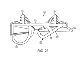
- FIG. 22 is a perspective view of a door sweep, according to one aspect of the present disclosure.
- FIG. 23 is a cross-sectional side elevation view of a threshold assembly having a self-articulating threshold cap not interacting with a door panel in an open position, according to one aspect of the present disclosure.
- FIG. 24 is a cross-sectional side elevation view of a threshold assembly having a self-articulating threshold cap interacting with a door sweep of a door panel between a closed and an open position.
- FIGS. 1-6 each illustrate an entryway system 10 having a threshold assembly 11 including a threshold substrate 12 , which, in some instances, may be a unitarily molded plastic workpiece.
- the threshold substrate 12 may be configured to define a longitudinally extending upwardly open sill channel 13 .
- the sill channel 13 is flanked along its outside edge by a first wall (e.g., upstanding substrate dam 14 ) and along its inside edge by a second wall (e.g., an integrally formed nosing 15 ).
- the substrate dam 14 and the nosing 15 form the outside and inside walls, respectively, of the upwardly open sill channel 13 .
- the upwardly open sill channel 13 is sized to receive a threshold cap 100 (self-adjustable (see FIG.
- the threshold substrate 12 projects outwardly a predetermined distance from the upstanding substrate dam 14 .
- the threshold substrate 12 preferably is made of a deterioration resistant material, but may be made of any other material with appropriate support such as, for example, wood. In some instances, the threshold substrate 12 may be formed by a traditional injection molding process, or by an extrusion process.
- a nosing strip 16 may be attached to an inside edge 17 of the sill channel 13 so as to extend upwardly therefrom over the nosing 15 .
- the nosing strip 16 may extend across the sill channel 13 to cover a floor 18 thereof.
- a downwardly projecting nosing barbed tab 19 can be positioned and configured to be snapped into place within a nosing attachment slot 20 to hold the nosing strip 16 securely in place within the sill channel 13 .
- a decking cover plate 21 may be attached with appropriate means (e.g., mechanical, adhesive, etc.) to the threshold substrate 12 and forms a main upper tread surface 22 of the threshold assembly 11 .
- the decking cover plate 21 may include an upstanding decking dam 23 that extends upward from the substrate dam 14 to provide a water entry barrier that reduces the amount of water directly entering the sill channel 13 .
- the decking cover plate 21 may have a contoured outside edge portion 24 (see FIGS. 14-19 ) configured to fit over the compatibly contoured forward edge 25 of the threshold substrate 12 .
- a downwardly projecting barbed decking tab 26 may be formed along an inside surface 27 of the decking cover plate 21 and may be positioned and configured to be snapped into place within a decking attachment slot 28 to hold the decking cover plate 21 securely in place on the threshold substrate 12 .
- the threshold assemblies 11 of FIGS. 1-6 have discrete components (e.g., the threshold substrate 12 , the decking cover plate 21 , and the nosing strip 16 ), it will be understood that this is not a limitation of the disclosure. That is, the threshold assembly 11 , for example, can be formed completely from an aluminum extrusion, can be formed completely from an extruded or injection molded plastic material, or may be a combination thereof.
- the particular construction of the threshold assembly 11 illustrated in FIGS. 1-6 is chosen because it is a common construction and because it serves well to illustrate the present disclosure. Those of skill in the art will understand, however, that a variety of threshold assembly constructions may well be used without departing from the spirit of the present disclosure.
- the elongated threshold cap 100 is disposed in and projects upwardly from the upwardly open sill channel 13 .
- the threshold cap 100 may be formed of single or multiple materials or components, wherein such suitable materials may include wood, plastic, a composite, or another appropriate material.
- the threshold cap 100 is positioned to underlie a closed door panel 200 mounted in an entryway that includes the threshold assembly 11 .
- an array of vertical adjustment screw mechanisms 29 may be provided for selectively and manually adjusting the height of the threshold cap 100 such that the threshold cap 100 sealingly engages a door sweep 300 mounted to a bottom edge 201 of a closed door panel 200 to form a seal between the bottom edge 201 of the door panel 200 and the threshold cap 100 .
- a door sweep 300 can be formed of multiple components. Accordingly, the phrase door sweep is sometimes referred to herein as a door sweep assembly.
- a gap 30 may be formed between the forward cap edge 31 of the threshold cap 100 and an inside surface 32 of the substrate dam 14 that defines an outside wall of the upwardly open sill channel 13 .
- the gap 30 may be in the range of about 0.08 inches (2.03 mm) to about 0.20 inches (5.08 mm) between the forward cap edge 31 and the inside surface 32 .
- a common dimension of the gap 30 in the threshold assembly 11 may be about 0.14 inches (3.55 mm). Since the gap 30 is exposed to the elements on the outside of a building structure, it can afford the opportunity for rainwater to leak or seep into the upwardly open sill channel 13 and ultimately to the sub floor upon which the threshold assembly 11 rests.
- prior threshold assemblies have attempted to provide a watertight barrier within or otherwise about the gap 30 , using sealing provisions, such as, for example, weatherstripping, flexible foam tape, etc., to prevent water from entering the sill channel 13 .
- sealing provisions such as, for example, weatherstripping, flexible foam tape, etc.
- prior threshold assemblies intend to prevent water from entering the interior of the building structure by attempting to plug all possible water entry points.
- this is difficult to achieve and such sealing provisions typically allow at least some incidental water to seep or otherwise leak into the sill channel 13 .
- Such prior threshold assemblies may thus provide drain systems that attempt to remove the incidental water from the sill channel 13 .
- such prior drain systems may only be capable of handling minimal amounts of water (i.e., incidental water that has leaked through the seal and into the sill channel).
- prior threshold assemblies may not be equipped to handle non-incidental water (i.e., water that is naturally allowed to flow or otherwise enter the sill channel, rather than just minimally leak or seep into the sill channel).
- non-incidental water i.e., water that is naturally allowed to flow or otherwise enter the sill channel, rather than just minimally leak or seep into the sill channel.
- such prior threshold assemblies may have not envisioned allowing such non-incidental water to enter the threshold assembly. Accordingly, aspects of the present disclosure seek to allow non-incidental water to enter the threshold assembly 11 and then appropriately manage such non-incidental water.
- the entryway system 10 of the present disclosure is configured to allow water to enter the sill channel 13 on the exterior of any sealing provisions and then manages the water and provides an avenue for water drainage out of the threshold assembly 11 .
- the gap 30 is not entirely filled or otherwise entirely protected with a sealing mechanism(s) and is, instead, allowed to remain at least partially open-ended to receive non-incidental water therein.
- the present disclosure accepts that at least some water will enter the threshold assembly 11 regardless of the attempted sealing of the gap 30 , and, as such, the present disclosure provides a water management system that allows non-incidental water into the threshold assembly 11 and then appropriately manages the water out thereof.
- some aspects of the present disclosure are directed to providing an unobstructed water entry path from the gap 30 to the exterior of a building structure.
- water entry barrier provisions e.g., flange 304 , decking dam 23 , fin 301 (see FIG. 6 )
- such provisions do not obstruct the water entry path and instead may, in some instances, only assist in defining the water entry path.
- sealing provisions e.g., fin 301 (see FIGS. 2-4 ) may be provided wherein the water leaks or otherwise seeps through the sealing provision and into the sill channel 13 via the gap 30 .
- aspects of the present disclosure may provide the gap 30 as partially or entirely unobstructed such that water may flow directly into the sill channel 13 .
- the threshold cap 100 may be positioned or secured toward the nosing 15 such that the gap 30 is provided between the threshold cap 100 and the substrate dam 14 .
- Appropriate securement or fastening mechanisms may be provided for ensuring that the threshold cap 100 maintains its spacing from the substrate dam 14 to maintain the gap 30 . That is, the threshold cap 100 may be secured toward the nosing 15 so as to maintain the gap 30 .
- one or more spacers 33 may be positioned within the gap 30 to maintain the gap 30 between the forward cap edge 31 of the threshold cap 100 and an inside surface 32 of the substrate dam 14 .
- the spacers 33 are spaced apart from each other along a length of the sill channel 13 spanning an entryway, as shown in FIGS. 7-11 .
- the spacers 33 may define a spacer channel 34 ( FIGS. 1-6 ) configured to receive a portion of the threshold cap 100 (e.g., a cap leg 101 of a front wall 106 of the threshold cap 100 ) for securing the spacers 33 within the sill channel 13 .
- the spacers 33 may be disposed between the forward cap edge 31 of the threshold cap 100 and the inside surface 32 of the substrate dam 14 to maintain the gap 30 .
- water may enter the sill channel 13 between the spacers 33 . That is, since the spacers 33 do not extend along the length of the channel 13 to fully fill the gap 30 , there are formed openings 35 between the spacers 33 that allow water to enter the sill channel 13 . In this regard, portions of the gap 30 may be left unfilled such that no sealing mechanism is provided between the threshold cap 100 and the substrate dam 14 .
- a sealing provision e.g., a fin 301
- the door sweep 300 may limit the amount of water allowed to unimpededly enter the sill channel 13 , as shown in FIGS. 2-4 .
- the decking dam 23 may provide a similar function (i.e., providing at least some impedance to water entry into the threshold assembly 11 ).
- a single spacer 33 of unitary construction may be provided and extended partially or entirely along the length of the threshold assembly 11 , wherein the spacer 33 itself may define one or more vertical slots (not shown) extending therethrough or otherwise defined thereby that allow the water to enter the sill channel 13 .
- the spacers 33 may be of various configurations, as illustrated in FIGS. 1-6 .
- the specific configuration of the spacer may typically depend upon the type of threshold cap 100 incorporated into the threshold assembly 11 .
- the spacer 33 may interlock or otherwise securely engage the threshold cap 100 in an interference or snap fit.
- the spacer 33 may define a spacer channel 34 configured to receive a portion of the threshold cap 100 such as, for example, the cap leg 101 .
- the spacer 33 may be configured to accommodate the vertical adjustment screw mechanisms 29 associated with the vertically adjustable threshold cap 100 (FIGS. 2 and 4 - 6 ).
- the spacer 33 may include one or more spacer walls 56 capable of interacting with various portions of the threshold cap 100 .
- the spacer 33 may extend substantially entirely along the floor 18 of the sill channel 13 between the substrate dam 14 and the nosing 15 .
- the threshold substrate 12 is configured to direct the water from the sill channel 13 out of the threshold assembly 11 via a path that causes the water to eventually exit via one or more drain holes 36 (i.e., weep holes). More specifically, the water is directed out of the sill channel 13 through one or more drain channels 37 defined by the substrate dam 14 .
- the spacers 33 may be offset from the drain channels 37 such that the water can flow from the sill channel 13 into the drain channels 37 according to the corresponding drain path.
- the water may then be directed out of the drain holes 36 via gravity flow due to a substrate floor 38 of the threshold substrate 12 being downwardly sloped from the sill channel 13 toward the forward edge 25 of the threshold substrate 12 .
- FIGS. 10-13 illustrate a molded plastic threshold substrate 12 for installation in a threshold assembly 11 according to the present disclosure.
- the threshold substrate 12 is formed with the forward edge 25 , a back or inside edge 39 , and a pair of side edges 40 , 41 .
- the upwardly open channel 13 is defined adjacent and along the back edge 39 of the threshold substrate 12 for receiving and holding the threshold cap 100 .
- the upwardly open channel 13 is bounded along the back edge 39 of the threshold substrate 12 by the upstanding nosing 15 .
- An array of spaced apart support walls 42 extend from the substrate dam 14 proximate to the forward edge 25 of the threshold substrate 12 .
- the decking cover plate 21 may be snapped or otherwise secured in place on the threshold substrate 12 covering and being supported by the support walls 42 thereof.
- the substrate dam 14 , the support walls 42 , the forward edge 25 , and the side edges 40 , 41 cooperate to form a plurality of chambers 43 that, in some instances, may be continuously connected. That is, as shown in FIG. 10 , the support walls 42 do not extend to the forward edge 25 of the threshold substrate 12 . In this manner, the drain holes 36 may be positioned at opposing side ends of the threshold substrate 12 . In some instances, the chambers 43 may be closed such that water cannot flow from one chamber to another. In such instances, each chamber 43 may include a corresponding drain hole 36 for permitting removal of water therefrom. A deflector wall 44 may be provided so as to direct water toward the drain holes 36 . Additional back pressure walls 42 A, 42 B assist in preventing water inflow caused by back exterior pressure.
- the drain channels 37 which communicate with the sill channel 13 and the drain holes 36 , form a water management system for the threshold assembly 11 . More specifically, rain water that may collect in the sill channel 13 via the gap 30 is channeled away from the sill channel 13 by flowing to the forward edge 25 of the threshold substrate 12 , into the drain channels 37 , through the chambers 43 , and out the drain holes 36 . In this manner, the non-incidental rainwater is appropriately managed such that there is no path for water to leak beneath the threshold assembly and rot or otherwise deteriorate the subfloor upon which it rests and all water is drained to the forward edge of the threshold assembly 11 and out thereof.
- the outside edge portion 24 of the decking cover plate 21 fits over the forward edge 25 of the threshold substrate 12 .
- the forward edge 25 of the threshold substrate 12 may define a lip 45 extending beyond a forward wall 46 of the threshold substrate 12 , which may be substantially perpendicular to the substrate floor 38 ( FIGS. 11-12 );
- the outside edge portion 24 of the decking cover plate 21 may be correspondingly configured to mate with the lip 45 , such as, for example, the outside edge portion 24 having a U-shaped profiled configured to wrap about the lip 45 .
- the decking cover plate 21 terminates above the ground surface such that the drain holes 36 (as defined by the forward wall 46 of the threshold substrate 12 ) are not covered thereby. That is, the outside edge portion 24 does not extend the entire height of the forward wall 46 so as to leave a portion thereof uncovered.
- Such a configuration eliminates the need to provide or otherwise define corresponding drain holes in the decking cover plate 21 .
- one or more air inlets 50 may be provided in addition to and separate from the drain holes 36 .
- the air inlets 50 allow air to enter the chambers 43 defined, for example, between the threshold substrate 12 and the decking cover plate 21 .
- the forward wall 46 of the threshold substrate 12 may at least partially define the air inlets 50 (e.g., slots) at an upper end 47 thereof for allowing air to enter the chambers 43 .
- the one or more air inlets 50 may be provided in an elevated arrangement with respect to the drain holes 36 . In such a configuration, the water may exit the threshold assembly 11 through the drain holes 36 and not through the air inlet(s) 50 .
- the forward wall 46 may be injection molded with recesses that define the air inlets 50 .
- the air inlets 50 may extend from a vertical surface 48 of the forward wall 46 and over a chamfered portion 55 and a top surface 49 of the forward edge 25 , such that the decking cover plate 21 is flush against the top surface 49 of the forward edge 25 except at the recessed air inlets 50 . That is, the decking cover plate 21 cooperates with the forward wall 46 and forward edge 25 of the threshold substrate to form the air inlets 50 , wherein the decking cover plate 21 provides an upper barrier.
- Such separate air inlets 50 and drain holes 36 provide advantages over prior art threshold assemblies, which have drain holes that provide both an exit for water and an inlet for air to enter the threshold assembly 11 for equalizing air pressure therein.
- the drain holes typically are used not only to provide an exit for water, but to also allow air to enter the threshold assembly for equalizing air pressure therein.
- such configurations typically allow air to enter the drain holes to the detriment of allowing water to exit therefrom.
- allowing air to enter only through the drain holes can create a bubbling effect.
- aspects of the present disclosure provide air inlets 50 separate from the drain holes 36 , which allows air to enter the chambers 43 via a mechanism other than the drain holes 36 .
- the threshold assembly 11 may include a self-articulating or self-adjusting threshold cap 100 . That is, one aspect of the present disclosure is a self-articulating threshold cap 100 capable of self-adjusting to sealingly interact with the underside of the door panel 200 or otherwise with the door sweep 300 attached to the underside of the door panel 200 . In other words, the threshold cap 100 may self-bias against the door panel 200 to maintain contact therewith, regardless of settling of a building or other cause that creates additional or reduced space between the threshold cap 100 and the door panel 200 or door sweep 300 .
- the threshold cap 100 may be configured for removal and replacement within a threshold assembly 11 either before or after installation thereof in an entryway.
- the threshold cap 100 may include a mechanism, integral or otherwise, causing it to naturally remain in contact with the door panel 200 as intended.
- the threshold cap 100 is not manually adjusted, but instead may be displaced by the movement of the mating door panel 200 or the door sweep assembly 300 .
- the threshold cap 100 may be integrally formed and may be constructed from a plastic or polymeric material using, for example, an extrusion process.
- the material of construction of the threshold cap 100 may have an elastomeric feature that allows the threshold cap 100 to inherently bias against the door panel 200 when in contact therewith. That is, the threshold cap 100 may be formed of a polymeric material that permits at least a portion thereof to flex or otherwise deflect in accordance with the structural aspects of the present disclosure. In this regard, the threshold cap 100 may include an integral feature causing a portion thereof to tend to stay in a position biased toward the door panel 200 or the door sweep assembly 300 . According to some aspects, the threshold cap 100 may include supplemental biasing mechanisms used to assist a portion of the threshold cap 100 to tend to stay in an upward position (e.g., a biasing spring 51 ).
- the threshold cap 100 may include an articulating top portion 102 having a continuous surface 103 capable of interacting with the door panel 200 or the door sweep assembly 300 .
- the threshold cap 100 may include a bottom support wall 104 capable of being disposed within the sill channel 13 to engage the floor 18 thereof.
- a rear wall 105 may extend perpendicularly from the bottom support wall 104 .
- the rear wall 105 may include a projection 114 capable of interacting with the nosing 15 or the nosing strip 16 (when provided) to form a sealing barrier therewith.
- a front wall 106 may depend from the bottom support wall 104 or otherwise be connected thereto via, for example, an arcuate portion 113 , and at least a portion of the front wall 106 may be substantially perpendicular to the bottom support wall 104 .
- the front wall 106 may include an extension, such as, for example, the cap leg 101 , configured to be securely received within the spacer channel 34 .
- the articulating top portion 102 extends from the front wall 106 .
- the articulating top portion 102 is configured to self-bias against the underside of the door panel 200 or the door sweep assembly 300 when the door panel 200 is in the closed position.
- the articulating top portion 102 may include a top wall 107 and a locking wall 108 extending substantially perpendicular to the top wall 107 .
- the threshold cap 100 may further include an intermediate wall 109 disposed between the rear wall 105 and the front wall 106 .
- the intermediate wall 109 acts to constrain the articulating top portion 102 .
- the intermediate wall 109 may include a first leg 110 and a second leg 111 .
- the first leg 110 may extend perpendicularly from the bottom support wall 104 .
- the second leg 111 may depend perpendicularly from the first leg 110 toward the rear wall 105 .
- the locking wall 108 may extend between the rear wall 105 and the second leg 111 .
- the locking wall 108 may have a hook portion 112 configured to interact with the second leg 111 to prevent the locking wall 108 from advancing therepast.
- a cap leg 101 may be provided for being received within the spacer channel 34 such that each spacer 33 is maintained within the sill channel 13 . It is noted that the described legs, walls, and portions of the threshold cap 100 substantially extend along the entire length thereof.
- FIG. 23 illustrates one aspect of a threshold assembly 11 according to the present disclosure in which the door panel 200 is in an open position, wherein the threshold cap 100 is not interacting with the door sweep assembly 300 .
- the self-articulating threshold cap 100 may include the biasing spring 51 or other biasing mechanism configured to bias the articulating top portion 102 of the threshold cap 100 in an upwardly position for interacting with the door sweep assembly 300 .
- the biasing spring 51 or other biasing mechanism may be disposed within a cavity 115 generally defined by the threshold cap 100 and extending along the length thereof.
- the cavity 115 may be defined by the bottom support wall 104 , the arcuate portion 113 , the front wall 106 , the intermediate wall 109 , and the articulating top portion 102 .
- FIG. 24 illustrates the door panel 200 in a partially closed position, wherein the door sweep assembly 300 has started to engage and interact with the threshold cap 100 .
- the door sweep assembly 300 interacts with the threshold cap 100 so as to force the top portion 102 thereof downward such that at least a portion of the door sweep assembly 300 can advance therepast. More particularly, the door sweep assembly 300 interacts with the top portion 102 to force the top wall 107 downward from an inclined position to an orientation substantially parallel to the bottom support wall 104 . In this manner, the top portion 102 may move from a biased position to an unbiased position when interacting with the door panel 200 or the door sweep assembly 300 .
- FIG. 1 illustrates the door panel 200 in a closed position, wherein the door sweep assembly 300 is entirely engaged with the threshold cap 100 along the length of the threshold assembly 11 .
- the top portion 102 of the threshold cap 100 is biased upward toward the door panel 200 to sealingly interact with one or more portions of the door sweep assembly 300 to form a sealing barrier.
- at least one portion of the nosing strip 16 may be configured to contact the threshold cap 100 along the length of the threshold assembly 100 so as to form an additional seal therewith.
- both the door sweep assembly 300 and the nosing strip 16 may be configured to contact the threshold cap 100 upon closing of the door panel 200 such that multiple sealing barriers are formed along the length of the threshold assembly 11 .
- the nosing strip 16 which may be of extruded plastic with a wood grain or other appropriate appearance, may be snapped or otherwise attached into place covering the nosing 15 of the threshold substrate 12 .
- the nosing strip 16 which is visible from the inside of a building structure, covers the nosing 15 of the threshold substrate 12 and hides any junctions between adjacent threshold substrates 12 .
- the nosing strip 16 may include a nosing portion 52 , a nosing fin 53 , and a sill channel cover portion 54 .
- the nosing portion 52 may extend about the nosing 15 of the threshold substrate 12 , from within the sill channel 13 to the back edge 39 of the threshold substrate 12 .
- a barbed tab 19 of the nosing strip 16 may be configured to be received within the nosing attachment slot 20 so as to engage the threshold substrate 12 for anchoring thereto.
- the nosing fin 53 may be flexible and capable of interacting with the locking wall 108 of the threshold cap 100 to form an additional seal along the length of the threshold assembly 11 .
- a resilient sealing provision e.g., bulb 302
- the door sweep assembly 300 may sealingly contact the nosing strip 16 , and top wall 107 .
- the nosing strip 16 may extend across the floor 18 of the sill channel 13 .
- the nosing strip 16 may be used to extend across adjacent interlocking threshold substrates 12 for covering a seam formed between the adjacent threshold substrates 12 , as disclosed in U.S. Pat. No. 7,350,336 to Bennett, which is assigned to Endura Products, Inc. (also the assignee of the present disclosure), and which is hereby incorporated herein by reference in its entirety.
- the door sweep assembly 300 may be integral with or otherwise attached, secured or fixed to a bottom portion of the door panel 200 .
- the door panel 200 includes an underside or bottom edge 201 with the door sweep assembly 300 flush thereagainst.
- the door sweep assembly 300 may include a support wall 303 secured to the bottom edge 201 of the door panel 200 and extending along the width thereof.
- the door sweep assembly 300 may be attached to the door panel 200 using, for example, one or more door sweep barbs 306 (as shown in FIG. 22 ) capable of being received within corresponding door slots (not shown) defined by the door panel 200 .
- a flange 304 , an arm 305 , and the resilient bulb 302 depend from the support wall 303 .
- the flange 304 and resilient bulb 302 are preferably flexible, while arm 305 is preferably rigid. In some instances, all three may be integrally formed with the support wall 303 . While it is preferred that bulb 302 be generally ovoid, other suitable shapes are possible. It should be understood that bulb 302 extends the length of the door sweep assembly 300 , but since the cross-sectional shape is bulb-like, it is described as a bulb.
- the flange 304 may include a flexible seal fin 307 that fits between to the door panel 200 and support wall 303 for sealing the joint between the door panel 200 and door sweep assembly 300 , thus preventing water penetration along the joint.
- the rigid arm 305 can be configured to interact with the threshold cap 100 so as to force the articulating top portion 102 thereof in a substantially downward direction (toward the floor 18 of the sill channel 13 ) as the door panel 200 is moved to the closed position.
- the rigid arm 305 continues to maintain contact with the threshold cap 100 due to the upward biasing thereof by, for example, the biasing spring 51 , thereby forming a first seal along the length of the entryway system 10 .
- the rigid arm 305 interacts with the surface 103 and compresses the articulating top portion 102 of the threshold cap 100 into an unbiased position.
- the rigid arm 305 may be constructed of any suitable material, such as, for example, a plastic material, and may be integrally formed with the support wall 303 .
- the rigid arm 305 may include an arcuate portion 308 and an inclined portion 309 , both configured to interact with the threshold cap 100 such that the threshold cap 100 is initially forced downward and then allowed to bias against the door sweep assembly 300 .
- the inclined portion 309 may be in a sloped configuration with respect to the support wall 303 such that the inclined portion 309 provides the initial contact between the door sweep assembly 300 and the threshold cap 100 .
- the top portion 102 of the threshold cap 100 then rides along the inclined portion 309 , towards the arcuate portion 308 , so as to maintain contact therewith as the door panel 200 is moved to the closed position.
- the arcuate portion 308 eventually contacts the top portion 102 and forces the top portion 102 downward to a lower position. As the arcuate portion 308 moves along the top wall 107 , while maintaining contact therewith due to the upward biasing of the threshold cap 100 , the top portion 102 moves upward away from the floor 18 and into sealing contact with the door sweep assembly 300 upon the door being in a fully closed position.
- the bulb 302 may be configured to sealingly interact with the threshold cap 100 , thereby forming a second seal along the length of the entryway system 10 .
- the bulb 302 may also be capable of contacting the nosing strip 16 to form an additional sealing barrier along the length of the entryway system 10 , as shown in FIG. 1 .
- the door sweep assembly 300 and the threshold cap 100 when used together, provide a strong positive seal between the door panel 200 and the threshold assembly 11 .
Landscapes
- Engineering & Computer Science (AREA)
- Civil Engineering (AREA)
- Structural Engineering (AREA)
- Building Environments (AREA)
- Specific Sealing Or Ventilating Devices For Doors And Windows (AREA)
Abstract
Description
Claims (17)
Priority Applications (1)
| Application Number | Priority Date | Filing Date | Title |
|---|---|---|---|
| US14/013,675 US8991101B2 (en) | 2011-08-23 | 2013-08-29 | Door entryway system |
Applications Claiming Priority (2)
| Application Number | Priority Date | Filing Date | Title |
|---|---|---|---|
| US13/215,905 US8522483B2 (en) | 2011-08-23 | 2011-08-23 | Door entryway system |
| US14/013,675 US8991101B2 (en) | 2011-08-23 | 2013-08-29 | Door entryway system |
Related Parent Applications (1)
| Application Number | Title | Priority Date | Filing Date |
|---|---|---|---|
| US13/215,905 Continuation US8522483B2 (en) | 2011-08-23 | 2011-08-23 | Door entryway system |
Publications (2)
| Publication Number | Publication Date |
|---|---|
| US20140318020A1 US20140318020A1 (en) | 2014-10-30 |
| US8991101B2 true US8991101B2 (en) | 2015-03-31 |
Family
ID=47741367
Family Applications (2)
| Application Number | Title | Priority Date | Filing Date |
|---|---|---|---|
| US13/215,905 Active 2031-09-14 US8522483B2 (en) | 2011-08-23 | 2011-08-23 | Door entryway system |
| US14/013,675 Active 2031-09-15 US8991101B2 (en) | 2011-08-23 | 2013-08-29 | Door entryway system |
Family Applications Before (1)
| Application Number | Title | Priority Date | Filing Date |
|---|---|---|---|
| US13/215,905 Active 2031-09-14 US8522483B2 (en) | 2011-08-23 | 2011-08-23 | Door entryway system |
Country Status (2)
| Country | Link |
|---|---|
| US (2) | US8522483B2 (en) |
| CA (1) | CA2771705C (en) |
Cited By (17)
| Publication number | Priority date | Publication date | Assignee | Title |
|---|---|---|---|---|
| US20150191964A1 (en) * | 2011-08-23 | 2015-07-09 | Endura Products, Inc. | Door entryway system |
| DE202015105614U1 (en) * | 2015-10-22 | 2016-10-25 | Rehau Ag + Co. | Threshold profile for a window or door and window or door with such a threshold profile |
| USD775366S1 (en) | 2015-05-20 | 2016-12-27 | Endura Products, Inc. | Door sweep |
| USD775368S1 (en) | 2015-05-20 | 2016-12-27 | Endura Products, Inc. | Door sweep |
| USD775367S1 (en) | 2015-05-20 | 2016-12-27 | Endura Products, Inc. | Door sweep |
| US20170081908A1 (en) * | 2015-05-20 | 2017-03-23 | Endura Products, Inc. | Entryway with articulating threshold |
| USD797309S1 (en) | 2016-03-14 | 2017-09-12 | Endura Products, Inc. | Threshold cap |
| USD812772S1 (en) | 2016-12-21 | 2018-03-13 | Global Products International Group, Llc | Low dam outswing sill cap |
| USD820470S1 (en) | 2016-12-21 | 2018-06-12 | Global Products International Group, Llc | High dam outswing sill cap |
| US10077593B2 (en) | 2014-11-26 | 2018-09-18 | Quanex Homeshield Llc | Threshold assembly for an entryway system |
| US10202795B2 (en) | 2015-10-13 | 2019-02-12 | Endura Products, Inc. | Doorsill |
| USD875969S1 (en) | 2015-05-20 | 2020-02-18 | Endura Products, Inc. | Threshold cap |
| USD903902S1 (en) | 2015-05-20 | 2020-12-01 | Endura Products, Llc | Threshold cap |
| US10858881B2 (en) | 2018-04-25 | 2020-12-08 | Endura Products, Llc | Threshold and threshold cap |
| US11072969B2 (en) | 2018-09-11 | 2021-07-27 | Endura Products, Llc | Door sill system, apparatus and methods for a door assembly |
| US11085229B2 (en) | 2018-07-23 | 2021-08-10 | Endura Products, Llc | Threshold and threshold cap assembly |
| US11732525B2 (en) | 2021-02-02 | 2023-08-22 | Endura Products, Llc | Door sill system, apparatus, and methods for a door assembly |
Families Citing this family (26)
| Publication number | Priority date | Publication date | Assignee | Title |
|---|---|---|---|---|
| US8567128B2 (en) | 2011-01-19 | 2013-10-29 | Endura Products, Inc. | Door sill assemblies with replaceable sill decks |
| US8522483B2 (en) | 2011-08-23 | 2013-09-03 | Endura Products, Inc. | Door entryway system |
| US8813427B2 (en) | 2012-05-17 | 2014-08-26 | Quanex Corporation | Threshold assembly having a rail and a drainage element |
| US8726575B1 (en) * | 2013-03-13 | 2014-05-20 | Shurtech Brands, Llc | Door or window seal |
| US9920567B2 (en) * | 2013-03-15 | 2018-03-20 | Pemko Manufacturing Company, Inc. | Threshold |
| FR3003595B1 (en) * | 2013-03-25 | 2015-05-15 | Weser | PREFABRICATED DOOR THRESHOLD WITH EASY ACCESS |
| US8739469B1 (en) * | 2013-03-28 | 2014-06-03 | Endura Products, Inc. | Protective cover |
| USD722388S1 (en) | 2013-05-23 | 2015-02-10 | Endura Products, Inc. | Articulating threshold cap base |
| USD733927S1 (en) | 2013-09-05 | 2015-07-07 | Endura Products, Inc. | Threshold deck clip |
| US20150096235A1 (en) * | 2013-10-09 | 2015-04-09 | Oded Eddy Rochman | Door sill assembly, door sill and kit therefor |
| US9562387B2 (en) * | 2014-04-24 | 2017-02-07 | Quanex Homeshield Llc | Door bottom system for an entryway system |
| US9097059B1 (en) * | 2014-05-01 | 2015-08-04 | Andersen Corporation | Draining sill and frame assembly incorporating the same |
| US9487992B2 (en) * | 2014-11-26 | 2016-11-08 | Quanex Corporation | Threshold assembly for an entryway system |
| US20160215555A1 (en) * | 2015-01-23 | 2016-07-28 | Quanex Corporation | Sill Assembly for a Threshold System and a Method of Producing the Same |
| US9624716B2 (en) | 2015-05-20 | 2017-04-18 | Endura Products, Inc. | Multi-layer sealing spacer for entryway components |
| US9816311B2 (en) * | 2015-07-17 | 2017-11-14 | Eutimio Reyes | Portable barrier for a door sill |
| US20180119484A1 (en) * | 2016-10-28 | 2018-05-03 | Endura Products, Inc. | Door sweep and method for installing a door sweep |
| US10100570B1 (en) * | 2017-03-27 | 2018-10-16 | Tejas Specialty Group, Inc. | Threshold gasket assembly |
| US10815721B2 (en) | 2017-04-21 | 2020-10-27 | Endura Products, Llc | Entryway sealing spacer |
| CA3025069A1 (en) * | 2017-11-24 | 2019-05-24 | Novatech Canada Inc. | Door system with dual sealing elements |
| CN107956372A (en) * | 2017-12-01 | 2018-04-24 | 江苏远翔装饰工程有限公司 | Accessible high-air-tightness outward swinging door |
| US10612291B2 (en) * | 2018-01-12 | 2020-04-07 | Mjb Wood Group, Llc | Door threshold assembly |
| USD873440S1 (en) * | 2018-04-25 | 2020-01-21 | Endura Products, Inc. | Threshold cap |
| CN110552608B (en) * | 2018-05-31 | 2024-08-23 | 北京天乐交控科技发展有限公司 | Sealing structure of sliding plug door |
| US11174673B2 (en) | 2019-05-24 | 2021-11-16 | Nana Wall Systems, Inc. | Threshold sill with removable barrier insert |
| GB2591293B (en) * | 2020-01-27 | 2023-08-30 | Garner Aluminium Extrusions Ltd | An ancillary member |
Citations (91)
| Publication number | Priority date | Publication date | Assignee | Title |
|---|---|---|---|---|
| US56046A (en) | 1866-07-03 | Improved weather-strip | ||
| US220460A (en) | 1879-10-07 | Improvement in water-proof thresholds | ||
| US313742A (en) | 1885-03-10 | Threshold | ||
| US435658A (en) | 1890-09-02 | Weather-strip | ||
| US582451A (en) | 1897-05-11 | James c | ||
| US600301A (en) | 1898-03-08 | Combined threshold and weather strip | ||
| US618013A (en) | 1899-01-17 | Threshold for doors | ||
| US1468958A (en) | 1921-03-19 | 1923-09-25 | Raymond W Champion | Weather seal for thresholds |
| US1595827A (en) | 1926-04-29 | 1926-08-10 | Frisque Victor | Adjustable threshold |
| US1795853A (en) | 1929-06-12 | 1931-03-10 | Glass Booker Hughe | Rainproof saddle for weather-strip exterior doors |
| US2108137A (en) | 1936-04-18 | 1938-02-15 | Philip R Oftedal | Threshold |
| US2129381A (en) | 1935-08-17 | 1938-09-06 | Oftedal | Threshold construction |
| US2202482A (en) | 1938-12-10 | 1940-05-28 | Maurice S Oftedal | Weather strip |
| US2663056A (en) | 1950-09-27 | 1953-12-22 | Walter H Hardgrave | Weatherstrip |
| US2696029A (en) | 1953-06-11 | 1954-12-07 | Lewis T Neff | Weather strip |
| US2728118A (en) | 1952-12-22 | 1955-12-27 | John M Gossen | Adjustable thresholds |
| US2818614A (en) | 1956-07-23 | 1958-01-07 | Jr Frank Lapka | Threshold |
| US3083420A (en) | 1960-04-21 | 1963-04-02 | Tinflow Lionel | Weather resistant door saddle |
| US3114180A (en) | 1962-03-12 | 1963-12-17 | Marvin W Riedl | Adjustable threshold structure |
| US3273287A (en) | 1964-06-29 | 1966-09-20 | Pease Woodwork Company Inc | Sill and threshold assembly |
| US3374579A (en) | 1966-04-29 | 1968-03-26 | Edsel B. Neff | Adjustable threshold |
| US3402512A (en) | 1966-05-31 | 1968-09-24 | Francis C. Peterson | Adjustable threshold |
| US3432966A (en) | 1967-04-28 | 1969-03-18 | Crane Plastics Inc | Combination interlock and weather seal strip arrangement for relatively slidable closure members |
| US3475866A (en) | 1968-02-28 | 1969-11-04 | Bergiton Johansen | Adjustable threshold |
| US3762100A (en) | 1971-09-24 | 1973-10-02 | Taylor Garage Doors Inc | Threshold and sill assembly |
| US3854246A (en) | 1971-09-13 | 1974-12-17 | Combustion Eng | Threshold weatherstrip |
| US3900967A (en) | 1974-07-26 | 1975-08-26 | Pease Co | Adjustable sill and threshold assembly |
| US3967412A (en) | 1975-09-17 | 1976-07-06 | Peachtree Doors, Inc. | Adjustable threshold |
| US4055917A (en) | 1975-10-14 | 1977-11-01 | Elixir Industries | Door and threshhold assembly |
| US4079550A (en) | 1977-01-17 | 1978-03-21 | Pease Company | Composite sill assembly |
| US4104830A (en) | 1977-07-11 | 1978-08-08 | Fred Eagle | Adjustable threshold |
| US4146995A (en) | 1975-06-02 | 1979-04-03 | Britt Robert E | Adjustable thresholds and methods of making and using the same |
| US4156325A (en) | 1977-10-21 | 1979-05-29 | Edgett Edgar I | Sill kit or assembly |
| US4213275A (en) | 1979-04-02 | 1980-07-22 | Oehmig Robert G | Threshold and door sealing structure |
| US4224766A (en) | 1979-05-21 | 1980-09-30 | Endura Products, Inc. | Threshold with flexible insulator |
| US4287684A (en) | 1979-08-15 | 1981-09-08 | General Products Company, Inc. | Threshold with adjustable weather seal |
| US4310991A (en) | 1979-09-26 | 1982-01-19 | Embossed Door Corporation | Door sealing system |
| US4352258A (en) | 1980-08-04 | 1982-10-05 | Pease Company | Adjustable sill and threshold |
| US4387535A (en) | 1981-12-07 | 1983-06-14 | Manco Tape, Inc. | Adjustable threshold assembly |
| US4411104A (en) | 1980-11-12 | 1983-10-25 | Lst Corporation | Inswing door bottom and sill assembly |
| US4447989A (en) | 1982-03-16 | 1984-05-15 | Minnesota Mining And Manufacturing Company | Adjustable weatherstrip assembly |
| US4447987A (en) | 1981-03-19 | 1984-05-15 | Decor Doors Manufacturing Ltd. | Adjustable threshold and sill assembly |
| US4513536A (en) | 1982-11-12 | 1985-04-30 | Donat Flamanc Inc. | Weather tight seal for the sill of a household door |
| US4525953A (en) | 1983-10-14 | 1985-07-02 | Stutzman Ellis D | Weather seal with wide range of flexure |
| US4625457A (en) | 1985-05-30 | 1986-12-02 | Avery Phillip E | Insulating member for double doors |
| US4628639A (en) | 1985-08-08 | 1986-12-16 | Schlegel Corporation | Window frame weatherseal for a motor vehicle |
| US4716683A (en) | 1985-05-13 | 1988-01-05 | Rolscreen Company | Door weatherstripping assembly |
| US4831779A (en) | 1988-08-31 | 1989-05-23 | Schlegel Corporation | Self-draining panel threshold combination |
| EP0327840A2 (en) | 1988-02-06 | 1989-08-16 | Firma F. Athmer Sophienhammer | Magnetic seal for the gap between a floor and a door |
| US5010690A (en) | 1990-04-14 | 1991-04-30 | Imperial Products, Inc. | Adjustable threshold assembly with water-tight seals |
| US5012614A (en) | 1989-11-22 | 1991-05-07 | Shea Gregory T | Blow-molded unitary thermoplastic threshold |
| US5018307A (en) | 1990-04-25 | 1991-05-28 | Schlegel Corporation | Self-draining threshold for an out-swinging door |
| US5067279A (en) | 1991-02-04 | 1991-11-26 | Rolscreen Company | Self draining door threshold |
| US5136814A (en) | 1991-05-09 | 1992-08-11 | Headrick Management Corporation | Draining door sill assembly with adjustable threshold cap |
| US5179804A (en) | 1991-10-31 | 1993-01-19 | Young Robert H | Self draining door sill assembly |
| US5426894A (en) | 1993-12-03 | 1995-06-27 | Headrick; J. Charles | Continuous sidelight sill with adaptable threshold caps |
| US5588266A (en) | 1993-12-03 | 1996-12-31 | Headrick; J. Charles | Continuous sidelight sill with adaptable threshold caps and removable paint shield |
| US5592782A (en) | 1993-01-21 | 1997-01-14 | Crane Plastics Company Limited Partnership | Polymeric sealing/spring strip and exTrusion method of producing same |
| US5706607A (en) | 1994-09-17 | 1998-01-13 | Frey; Harry | Magnetic door seal |
| US5857291A (en) | 1996-12-20 | 1999-01-12 | Headrick Manufacturing Company | Astragal with integral sealing lock block |
| US5943825A (en) | 1998-08-26 | 1999-08-31 | Endura Products, Inc. | Entryway system and method |
| US6061967A (en) | 1999-01-19 | 2000-05-16 | Judds; Raymond E. | Overhead door sealing assembly |
| US6125584A (en) | 1994-12-29 | 2000-10-03 | Pemko Manufacturing Co. | Automatic door bottom |
| US6138413A (en) | 1996-12-12 | 2000-10-31 | Huron Window Corporation | Standardized framing section for closure wings |
| US6216395B1 (en) | 1999-02-08 | 2001-04-17 | Donald R. Kelly | Threshold protective cover |
| US6367201B1 (en) | 2000-03-10 | 2002-04-09 | Endura Products, Inc. | Width adaptable threshold assembly |
| US6371188B1 (en) | 1999-06-17 | 2002-04-16 | The Stanley Works | Doors assembly and an improved method for making a doors sill assembly |
| US20020194787A1 (en) | 2001-03-21 | 2002-12-26 | Bennett Joel S. | Threshold assembly with flexible watertight foam cap seal |
| US20030005644A1 (en) | 2001-07-06 | 2003-01-09 | Reithmeyer Joseph Guy | Adjustable door with sealed threshold, hinge and frame |
| USD488243S1 (en) | 2001-07-06 | 2004-04-06 | Andersen Corporation | Door sill portion |
| US6763639B2 (en) | 2000-07-10 | 2004-07-20 | Endura Products, Inc. | Threshold assembly with pre-fitted draining jamb boots and pre-fitted mull boots |
| US20040139667A1 (en) | 2002-10-01 | 2004-07-22 | The Stanley Works | Adjustable rail assembly for exterior door still assembly and components for the same |
| US6789358B2 (en) | 2000-11-01 | 2004-09-14 | Endura Products, Inc. | Threshold assembly with unitary molded substrate and jamb boot subassembly |
| US20040200153A1 (en) | 2003-04-10 | 2004-10-14 | Haik Khanlarian | Modular composite sill for threshold |
| US20050210754A1 (en) | 2004-03-15 | 2005-09-29 | Imperial Products, Inc. | Adjustable threshold assembly |
| US20060053695A1 (en) | 2004-09-10 | 2006-03-16 | Palenske Grant A | Integrated adjustable threshold |
| US20060174545A1 (en) | 2005-02-09 | 2006-08-10 | Young Robert H | Banded door sill base and door sill assembly, and method of forming same |
| US7114293B2 (en) | 2004-11-17 | 2006-10-03 | Holm Industries, Inc. | Magnetic door sweep and magnetic threshold assembly |
| US20060283087A1 (en) | 2005-06-21 | 2006-12-21 | Baxter Stephen M | Automatic door bottom and sill assemblage |
| USD549850S1 (en) | 2006-03-21 | 2007-08-28 | Richard Perlman | Door threshold |
| US20070227076A1 (en) | 2006-04-04 | 2007-10-04 | Therma-Tru Corp. | Entry system with water infiltration barrier |
| US7350336B2 (en) | 2001-05-29 | 2008-04-01 | Endura Products, Inc. | Continuous threshold assembly with modular interlocking substrate sections |
| US20080110100A1 (en) | 2006-11-09 | 2008-05-15 | Heppner Thomas J | Low profile, self-draining threshold assemblies |
| US20080229669A1 (en) | 2007-03-20 | 2008-09-25 | Endura Products, Inc. | Flip top adjustable threshold cap |
| US7472516B2 (en) | 2004-12-01 | 2009-01-06 | Quanex Corporation | Adjustable threshold assembly |
| US20090199486A1 (en) | 2008-02-12 | 2009-08-13 | Chad Wernlund | Doorway with anti-bubbling sill drain |
| US7600346B2 (en) | 2007-03-14 | 2009-10-13 | Quanex Corporation | Entryway system including a threshold assembly |
| US7669369B2 (en) | 2005-01-12 | 2010-03-02 | Michael Henry | Door threshold water return systems |
| USD638958S1 (en) | 2010-08-25 | 2011-05-31 | Endura Products, Inc. | Articulating threshold sill cap |
| US8074699B2 (en) | 2008-09-12 | 2011-12-13 | La Cantina Doors, Inc. | Zero step sill extruded flush threshold door seal system |
| US20130047518A1 (en) | 2011-08-23 | 2013-02-28 | Endura Products, Inc. | Door Entryway System |
Family Cites Families (1)
| Publication number | Priority date | Publication date | Assignee | Title |
|---|---|---|---|---|
| US4686793A (en) | 1986-06-23 | 1987-08-18 | Mills Norman J | Threshold |
-
2011
- 2011-08-23 US US13/215,905 patent/US8522483B2/en active Active
-
2012
- 2012-03-15 CA CA2771705A patent/CA2771705C/en active Active
-
2013
- 2013-08-29 US US14/013,675 patent/US8991101B2/en active Active
Patent Citations (95)
| Publication number | Priority date | Publication date | Assignee | Title |
|---|---|---|---|---|
| US220460A (en) | 1879-10-07 | Improvement in water-proof thresholds | ||
| US313742A (en) | 1885-03-10 | Threshold | ||
| US435658A (en) | 1890-09-02 | Weather-strip | ||
| US582451A (en) | 1897-05-11 | James c | ||
| US600301A (en) | 1898-03-08 | Combined threshold and weather strip | ||
| US618013A (en) | 1899-01-17 | Threshold for doors | ||
| US56046A (en) | 1866-07-03 | Improved weather-strip | ||
| US1468958A (en) | 1921-03-19 | 1923-09-25 | Raymond W Champion | Weather seal for thresholds |
| US1595827A (en) | 1926-04-29 | 1926-08-10 | Frisque Victor | Adjustable threshold |
| US1795853A (en) | 1929-06-12 | 1931-03-10 | Glass Booker Hughe | Rainproof saddle for weather-strip exterior doors |
| US2129381A (en) | 1935-08-17 | 1938-09-06 | Oftedal | Threshold construction |
| US2108137A (en) | 1936-04-18 | 1938-02-15 | Philip R Oftedal | Threshold |
| US2202482A (en) | 1938-12-10 | 1940-05-28 | Maurice S Oftedal | Weather strip |
| US2663056A (en) | 1950-09-27 | 1953-12-22 | Walter H Hardgrave | Weatherstrip |
| US2728118A (en) | 1952-12-22 | 1955-12-27 | John M Gossen | Adjustable thresholds |
| US2696029A (en) | 1953-06-11 | 1954-12-07 | Lewis T Neff | Weather strip |
| US2818614A (en) | 1956-07-23 | 1958-01-07 | Jr Frank Lapka | Threshold |
| US3083420A (en) | 1960-04-21 | 1963-04-02 | Tinflow Lionel | Weather resistant door saddle |
| US3114180A (en) | 1962-03-12 | 1963-12-17 | Marvin W Riedl | Adjustable threshold structure |
| US3273287A (en) | 1964-06-29 | 1966-09-20 | Pease Woodwork Company Inc | Sill and threshold assembly |
| US3374579A (en) | 1966-04-29 | 1968-03-26 | Edsel B. Neff | Adjustable threshold |
| US3402512A (en) | 1966-05-31 | 1968-09-24 | Francis C. Peterson | Adjustable threshold |
| US3432966A (en) | 1967-04-28 | 1969-03-18 | Crane Plastics Inc | Combination interlock and weather seal strip arrangement for relatively slidable closure members |
| US3475866A (en) | 1968-02-28 | 1969-11-04 | Bergiton Johansen | Adjustable threshold |
| US3854246A (en) | 1971-09-13 | 1974-12-17 | Combustion Eng | Threshold weatherstrip |
| US3762100A (en) | 1971-09-24 | 1973-10-02 | Taylor Garage Doors Inc | Threshold and sill assembly |
| US3900967A (en) | 1974-07-26 | 1975-08-26 | Pease Co | Adjustable sill and threshold assembly |
| US4146995A (en) | 1975-06-02 | 1979-04-03 | Britt Robert E | Adjustable thresholds and methods of making and using the same |
| US3967412A (en) | 1975-09-17 | 1976-07-06 | Peachtree Doors, Inc. | Adjustable threshold |
| US4055917A (en) | 1975-10-14 | 1977-11-01 | Elixir Industries | Door and threshhold assembly |
| US4079550A (en) | 1977-01-17 | 1978-03-21 | Pease Company | Composite sill assembly |
| US4104830A (en) | 1977-07-11 | 1978-08-08 | Fred Eagle | Adjustable threshold |
| US4156325A (en) | 1977-10-21 | 1979-05-29 | Edgett Edgar I | Sill kit or assembly |
| US4213275A (en) | 1979-04-02 | 1980-07-22 | Oehmig Robert G | Threshold and door sealing structure |
| US4224766A (en) | 1979-05-21 | 1980-09-30 | Endura Products, Inc. | Threshold with flexible insulator |
| US4287684A (en) | 1979-08-15 | 1981-09-08 | General Products Company, Inc. | Threshold with adjustable weather seal |
| US4310991A (en) | 1979-09-26 | 1982-01-19 | Embossed Door Corporation | Door sealing system |
| US4352258A (en) | 1980-08-04 | 1982-10-05 | Pease Company | Adjustable sill and threshold |
| US4411104A (en) | 1980-11-12 | 1983-10-25 | Lst Corporation | Inswing door bottom and sill assembly |
| US4447987A (en) | 1981-03-19 | 1984-05-15 | Decor Doors Manufacturing Ltd. | Adjustable threshold and sill assembly |
| US4387535A (en) | 1981-12-07 | 1983-06-14 | Manco Tape, Inc. | Adjustable threshold assembly |
| US4447989A (en) | 1982-03-16 | 1984-05-15 | Minnesota Mining And Manufacturing Company | Adjustable weatherstrip assembly |
| US4513536A (en) | 1982-11-12 | 1985-04-30 | Donat Flamanc Inc. | Weather tight seal for the sill of a household door |
| US4525953A (en) | 1983-10-14 | 1985-07-02 | Stutzman Ellis D | Weather seal with wide range of flexure |
| US4716683A (en) | 1985-05-13 | 1988-01-05 | Rolscreen Company | Door weatherstripping assembly |
| US4625457A (en) | 1985-05-30 | 1986-12-02 | Avery Phillip E | Insulating member for double doors |
| US4628639A (en) | 1985-08-08 | 1986-12-16 | Schlegel Corporation | Window frame weatherseal for a motor vehicle |
| EP0327840A2 (en) | 1988-02-06 | 1989-08-16 | Firma F. Athmer Sophienhammer | Magnetic seal for the gap between a floor and a door |
| US4831779A (en) | 1988-08-31 | 1989-05-23 | Schlegel Corporation | Self-draining panel threshold combination |
| US5012614A (en) | 1989-11-22 | 1991-05-07 | Shea Gregory T | Blow-molded unitary thermoplastic threshold |
| US5010690A (en) | 1990-04-14 | 1991-04-30 | Imperial Products, Inc. | Adjustable threshold assembly with water-tight seals |
| US5018307A (en) | 1990-04-25 | 1991-05-28 | Schlegel Corporation | Self-draining threshold for an out-swinging door |
| US5067279A (en) | 1991-02-04 | 1991-11-26 | Rolscreen Company | Self draining door threshold |
| US5136814A (en) | 1991-05-09 | 1992-08-11 | Headrick Management Corporation | Draining door sill assembly with adjustable threshold cap |
| US5179804A (en) | 1991-10-31 | 1993-01-19 | Young Robert H | Self draining door sill assembly |
| US5592782A (en) | 1993-01-21 | 1997-01-14 | Crane Plastics Company Limited Partnership | Polymeric sealing/spring strip and exTrusion method of producing same |
| US5588266A (en) | 1993-12-03 | 1996-12-31 | Headrick; J. Charles | Continuous sidelight sill with adaptable threshold caps and removable paint shield |
| US5426894A (en) | 1993-12-03 | 1995-06-27 | Headrick; J. Charles | Continuous sidelight sill with adaptable threshold caps |
| US5706607A (en) | 1994-09-17 | 1998-01-13 | Frey; Harry | Magnetic door seal |
| US6125584A (en) | 1994-12-29 | 2000-10-03 | Pemko Manufacturing Co. | Automatic door bottom |
| US6138413A (en) | 1996-12-12 | 2000-10-31 | Huron Window Corporation | Standardized framing section for closure wings |
| US5857291A (en) | 1996-12-20 | 1999-01-12 | Headrick Manufacturing Company | Astragal with integral sealing lock block |
| US5943825A (en) | 1998-08-26 | 1999-08-31 | Endura Products, Inc. | Entryway system and method |
| US6052949A (en) | 1998-08-26 | 2000-04-25 | Endura Products, Inc. | Entryway system and method |
| US6061967A (en) | 1999-01-19 | 2000-05-16 | Judds; Raymond E. | Overhead door sealing assembly |
| US6216395B1 (en) | 1999-02-08 | 2001-04-17 | Donald R. Kelly | Threshold protective cover |
| US6371188B1 (en) | 1999-06-17 | 2002-04-16 | The Stanley Works | Doors assembly and an improved method for making a doors sill assembly |
| US6367201B1 (en) | 2000-03-10 | 2002-04-09 | Endura Products, Inc. | Width adaptable threshold assembly |
| US6763639B2 (en) | 2000-07-10 | 2004-07-20 | Endura Products, Inc. | Threshold assembly with pre-fitted draining jamb boots and pre-fitted mull boots |
| US6789358B2 (en) | 2000-11-01 | 2004-09-14 | Endura Products, Inc. | Threshold assembly with unitary molded substrate and jamb boot subassembly |
| US20020194787A1 (en) | 2001-03-21 | 2002-12-26 | Bennett Joel S. | Threshold assembly with flexible watertight foam cap seal |
| US7350336B2 (en) | 2001-05-29 | 2008-04-01 | Endura Products, Inc. | Continuous threshold assembly with modular interlocking substrate sections |
| USD488243S1 (en) | 2001-07-06 | 2004-04-06 | Andersen Corporation | Door sill portion |
| US20030005644A1 (en) | 2001-07-06 | 2003-01-09 | Reithmeyer Joseph Guy | Adjustable door with sealed threshold, hinge and frame |
| US7263808B2 (en) | 2002-10-01 | 2007-09-04 | Premdor International, Inc. | Adjustable rail assembly for exterior door still assembly and components for the same |
| US20040139667A1 (en) | 2002-10-01 | 2004-07-22 | The Stanley Works | Adjustable rail assembly for exterior door still assembly and components for the same |
| US20040200153A1 (en) | 2003-04-10 | 2004-10-14 | Haik Khanlarian | Modular composite sill for threshold |
| US20050210754A1 (en) | 2004-03-15 | 2005-09-29 | Imperial Products, Inc. | Adjustable threshold assembly |
| US20060053695A1 (en) | 2004-09-10 | 2006-03-16 | Palenske Grant A | Integrated adjustable threshold |
| US7114293B2 (en) | 2004-11-17 | 2006-10-03 | Holm Industries, Inc. | Magnetic door sweep and magnetic threshold assembly |
| US7472516B2 (en) | 2004-12-01 | 2009-01-06 | Quanex Corporation | Adjustable threshold assembly |
| US7669369B2 (en) | 2005-01-12 | 2010-03-02 | Michael Henry | Door threshold water return systems |
| US20060174545A1 (en) | 2005-02-09 | 2006-08-10 | Young Robert H | Banded door sill base and door sill assembly, and method of forming same |
| US7644539B2 (en) | 2005-06-21 | 2010-01-12 | Stephen Marshall Baxter | Automatic door bottom and sill assemblage |
| US20060283087A1 (en) | 2005-06-21 | 2006-12-21 | Baxter Stephen M | Automatic door bottom and sill assemblage |
| USD549850S1 (en) | 2006-03-21 | 2007-08-28 | Richard Perlman | Door threshold |
| US20070227076A1 (en) | 2006-04-04 | 2007-10-04 | Therma-Tru Corp. | Entry system with water infiltration barrier |
| US20080110100A1 (en) | 2006-11-09 | 2008-05-15 | Heppner Thomas J | Low profile, self-draining threshold assemblies |
| US7600346B2 (en) | 2007-03-14 | 2009-10-13 | Quanex Corporation | Entryway system including a threshold assembly |
| US20080229669A1 (en) | 2007-03-20 | 2008-09-25 | Endura Products, Inc. | Flip top adjustable threshold cap |
| USD627488S1 (en) | 2007-03-20 | 2010-11-16 | Endura Products, Inc. | Flip top adjustable threshold cap |
| US20090199486A1 (en) | 2008-02-12 | 2009-08-13 | Chad Wernlund | Doorway with anti-bubbling sill drain |
| US8074699B2 (en) | 2008-09-12 | 2011-12-13 | La Cantina Doors, Inc. | Zero step sill extruded flush threshold door seal system |
| USD638958S1 (en) | 2010-08-25 | 2011-05-31 | Endura Products, Inc. | Articulating threshold sill cap |
| US20130047518A1 (en) | 2011-08-23 | 2013-02-28 | Endura Products, Inc. | Door Entryway System |
Non-Patent Citations (14)
| Title |
|---|
| AFCO Industries, Inc., Millwork Products Catalogue, pp. cover page, 6 (vinyl cap) and 9 (riser), believed available as of 2012. |
| American Architectural Manufacturers Association, AAMA AG-11 AAMA Glossary, believed to be available as of 2011, pp. 50 ("threshold"), 54 ("weatherstrip"), (http://www.aamanet.org/general/1/241/skylight-glossary-of-terms, accessed on Mar. 20, 2013). |
| Association of Millwork Distributors, Millwork Principles and Practices, believed to be available as of 2010, pp. cover page, 130 (door sill), 131 (threshold), 160 (adjustable sill), 162 (weatherstrip). |
| Combo Aluminum Products, 50th Anniversary Catalog, believed to be available 2008, cover page, pp. 1, 28 (hardwood cap), 31 (composite cap), 45 (foam weather-strip), (http://www.comboaluminum.com/Catalog/Combo-Aluminum-Catalog.pdf, accessed Mar. 20, 2013). |
| Endura Products, Glossary, 7 pages ("Cap/Riser", "Sill", "Weatherstrip"), available as of Aug. 22, 2011 (http://www.enduraproducts.com/technical-info/glossary.aspx, accessed Mar. 20, 2013). |
| Official Action of U.S. Appl. No. 13/215,905, dated Feb. 15, 2013, 17 pgs. |
| Official Action of U.S. Appl. No. 13/215,905, dated Nov. 14, 2012, 16 pgs. |
| Profile Selection Guide Building Products Division, Schlegel Systems, Inc., believed to be available as of Jun. 2008, page entitled T-Slot APTUS® TPE Weatherseals. |
| ThermaTru Doors Product Manual, Comp 13, Comp11, Jan. 2011 (online). Designs shown therein known at least as early as Aug. 24, 2010. Retrieved on Mar. 3, 2011: ; , 6 pgs. |
| ThermaTru Doors Product Manual, Comp 13, Comp11, Jan. 2011 (online). Designs shown therein known at least as early as Aug. 24, 2010. Retrieved on Mar. 3, 2011: <URL: www.thermatru.com/customer-support/technical-manuals/ArchComp/Comp-12-14.pdf>; <URL: http://www.thermatru.com/customer-support/technical-manuals/manuals/ArchComp/Comp11.pdf>, 6 pgs. |
| ThermaTru Doors Product Manual, Comp 13, Kerf Door Bottom, Jun. 2005, 2 pgs. |
| ThermaTru Doors, Sills Product Manual, Comp 11, Self-Adjusting Thermal Break Sill, Jun. 2005, 4 pgs. |
| Window & Door Manufacturers Association, The Door Glossary, AAMA/WDMA/CSA 101/I.S.2/A440-11, NAFS-North American Fenestration Standard/Specification for Windows, Doors, and Skylights, believed to be available 2011, (https://www.wdma.com/TechnicalCenter/TheDoorGlossary/tabid/84/Default.aspx, accessed on Mar. 20, 2013). |
| Window & Door Manufacturers Association, The Window Glossary, AAMA/WDMA/CSA 101/I.S.2/A440-11, NAFS-North American Fenestration Standard/Specification for Windows, Doors, and Skylights, believed to be available 2011, (https://www.wdma.com/TechnicalCenter/TheWindowGlossary/tabid/109/Default.aspx, accessed on Mar. 18, 2013). |
Cited By (26)
| Publication number | Priority date | Publication date | Assignee | Title |
|---|---|---|---|---|
| US10066433B2 (en) | 2011-08-23 | 2018-09-04 | Endura Products, Inc. | Door entryway system |
| US9371682B2 (en) * | 2011-08-23 | 2016-06-21 | Endura Products, Inc. | Door entryway system |
| US11193321B2 (en) | 2011-08-23 | 2021-12-07 | Endura Products, Llc | Door entryway system |
| US20150191964A1 (en) * | 2011-08-23 | 2015-07-09 | Endura Products, Inc. | Door entryway system |
| US10407975B2 (en) | 2011-08-23 | 2019-09-10 | Endura Products, Inc. | Door entryway system |
| US11346146B1 (en) | 2014-11-26 | 2022-05-31 | Quanex Homeshield, Llc | Threshold assembly for an entryway system |
| US11346145B1 (en) | 2014-11-26 | 2022-05-31 | Quanex Homeshield, Llc | Threshold assembly for an entryway system |
| US10801250B2 (en) | 2014-11-26 | 2020-10-13 | Quanex Homeshield, Llc | Threshold assembly for an entryway system |
| US10077593B2 (en) | 2014-11-26 | 2018-09-18 | Quanex Homeshield Llc | Threshold assembly for an entryway system |
| US20170081908A1 (en) * | 2015-05-20 | 2017-03-23 | Endura Products, Inc. | Entryway with articulating threshold |
| USD775368S1 (en) | 2015-05-20 | 2016-12-27 | Endura Products, Inc. | Door sweep |
| USD775366S1 (en) | 2015-05-20 | 2016-12-27 | Endura Products, Inc. | Door sweep |
| US9874054B2 (en) * | 2015-05-20 | 2018-01-23 | Endura Products, Inc. | Entryway with articulating threshold |
| USD903902S1 (en) | 2015-05-20 | 2020-12-01 | Endura Products, Llc | Threshold cap |
| USD775367S1 (en) | 2015-05-20 | 2016-12-27 | Endura Products, Inc. | Door sweep |
| USD875969S1 (en) | 2015-05-20 | 2020-02-18 | Endura Products, Inc. | Threshold cap |
| US10697228B2 (en) | 2015-10-13 | 2020-06-30 | Endura Products, Llc | Doorsill with mullion spacer |
| US10202795B2 (en) | 2015-10-13 | 2019-02-12 | Endura Products, Inc. | Doorsill |
| DE202015105614U1 (en) * | 2015-10-22 | 2016-10-25 | Rehau Ag + Co. | Threshold profile for a window or door and window or door with such a threshold profile |
| USD797309S1 (en) | 2016-03-14 | 2017-09-12 | Endura Products, Inc. | Threshold cap |
| USD820470S1 (en) | 2016-12-21 | 2018-06-12 | Global Products International Group, Llc | High dam outswing sill cap |
| USD812772S1 (en) | 2016-12-21 | 2018-03-13 | Global Products International Group, Llc | Low dam outswing sill cap |
| US10858881B2 (en) | 2018-04-25 | 2020-12-08 | Endura Products, Llc | Threshold and threshold cap |
| US11085229B2 (en) | 2018-07-23 | 2021-08-10 | Endura Products, Llc | Threshold and threshold cap assembly |
| US11072969B2 (en) | 2018-09-11 | 2021-07-27 | Endura Products, Llc | Door sill system, apparatus and methods for a door assembly |
| US11732525B2 (en) | 2021-02-02 | 2023-08-22 | Endura Products, Llc | Door sill system, apparatus, and methods for a door assembly |
Also Published As
| Publication number | Publication date |
|---|---|
| US20130047518A1 (en) | 2013-02-28 |
| US8522483B2 (en) | 2013-09-03 |
| CA2771705A1 (en) | 2013-02-23 |
| CA2771705C (en) | 2014-08-19 |
| US20140318020A1 (en) | 2014-10-30 |
Similar Documents
| Publication | Publication Date | Title |
|---|---|---|
| US8991101B2 (en) | Door entryway system | |
| US11193321B2 (en) | Door entryway system | |
| US9562387B2 (en) | Door bottom system for an entryway system | |
| US7600346B2 (en) | Entryway system including a threshold assembly | |
| US7775011B2 (en) | One-piece injection molded door sill assembly | |
| US7266929B1 (en) | Threshold and detachable sealing fin | |
| US8813427B2 (en) | Threshold assembly having a rail and a drainage element | |
| AU2010100406A4 (en) | Sliding windows, doors and the like | |
| US20060150521A1 (en) | Door threshold water return systems | |
| US20170342764A1 (en) | Door systems | |
| US10895103B2 (en) | Modular threshold assembly | |
| US7930860B2 (en) | Window drain | |
| US20050050815A1 (en) | Fenestration frame assemblies and associated methods | |
| US7941980B2 (en) | Window drain | |
| CA2842214C (en) | Door entryway system | |
| EP1516991A2 (en) | Doorsill structure for in-swinging type door | |
| AU2013273796B2 (en) | Closure framing system | |
| NZ709852B2 (en) | Closure framing system | |
| NZ619365B2 (en) | Closure framing system | |
| WO2015043605A1 (en) | Joint system |
Legal Events
| Date | Code | Title | Description |
|---|---|---|---|
| AS | Assignment |
Owner name: ENDURA PRODUCTS, INC., NORTH CAROLINA Free format text: ASSIGNMENT OF ASSIGNORS INTEREST;ASSIGNORS:VAN CAMP, BRENT;PROCTON, BRUCE E.;REEL/FRAME:031111/0600 Effective date: 20111006 |
|
| STCF | Information on status: patent grant |
Free format text: PATENTED CASE |
|
| MAFP | Maintenance fee payment |
Free format text: PAYMENT OF MAINTENANCE FEE, 4TH YEAR, LARGE ENTITY (ORIGINAL EVENT CODE: M1551); ENTITY STATUS OF PATENT OWNER: LARGE ENTITY Year of fee payment: 4 |
|
| AS | Assignment |
Owner name: BRANCH BANKING AND TRUST COMPANY, AS SECURED PARTY Free format text: NOTICE OF GRANT OF SECURITY INTEREST IN PATENTS;ASSIGNOR:ENDURA PRODUCTS, LLC;REEL/FRAME:051210/0019 Effective date: 20191202 Owner name: BRANCH BANKING AND TRUST COMPANY, AS SECURED PARTY, NORTH CAROLINA Free format text: NOTICE OF GRANT OF SECURITY INTEREST IN PATENTS;ASSIGNOR:ENDURA PRODUCTS, LLC;REEL/FRAME:051210/0019 Effective date: 20191202 |
|
| AS | Assignment |
Owner name: ENDURA PRODUCTS, LLC, NORTH CAROLINA Free format text: CONVERSION;ASSIGNOR:ENDURA PRODUCTS, INC.;REEL/FRAME:051257/0549 Effective date: 20191126 |
|
| MAFP | Maintenance fee payment |
Free format text: PAYMENT OF MAINTENANCE FEE, 8TH YEAR, LARGE ENTITY (ORIGINAL EVENT CODE: M1552); ENTITY STATUS OF PATENT OWNER: LARGE ENTITY Year of fee payment: 8 |
|
| AS | Assignment |
Owner name: JPMORGAN CHASE BANK, N.A., DELAWARE Free format text: SECURITY INTEREST;ASSIGNOR:ENDURA PRODUCTS, LLC;REEL/FRAME:062266/0370 Effective date: 20230103 |
|
| AS | Assignment |
Owner name: WELLS FARGO BANK, NATIONAL ASSOCIATION, GEORGIA Free format text: SECURITY AGREEMENT;ASSIGNOR:ENDURA PRODUCTS, LLC;REEL/FRAME:062277/0750 Effective date: 20230103 |
|
| AS | Assignment |
Owner name: ENDURA PRODUCTS, LLC, FLORIDA Free format text: TERMINATION AND RELEASE OF SECURITY INTEREST IN PATENTS;ASSIGNORS:CYPRIUM INVESTORS LP;CYPRIUM PARALLEL INVESTORS V LP;1492 CAPITAL, LLC;AND OTHERS;REEL/FRAME:062352/0177 Effective date: 20230105 |
|
| AS | Assignment |
Owner name: ENDURA PRODUCTS, LLC, FLORIDA Free format text: TERMINATION AND RELEASE OF SECURITY INTEREST IN PATENTS;ASSIGNOR:TRUIST BANK (FORMERLY KNOWN AS BRANCH BANKING AND TRUST COMPANY);REEL/FRAME:062357/0445 Effective date: 20230103 |
|
| AS | Assignment |
Owner name: ENDURA PRODUCTS, LLC, FLORIDA Free format text: RELEASE BY SECURED PARTY;ASSIGNOR:WELLS FARGO BANK, NATIONAL ASSOCIATION, AS COLLATERAL AGENT;REEL/FRAME:067664/0784 Effective date: 20240515 Owner name: ENDURA PRODUCTS, LLC, FLORIDA Free format text: TERMINATION AND RELEASE OF SECURITY INTEREST IN PATENTS;ASSIGNOR:JPMORGAN CHASE BANK, N.A., AS COLLATERAL AGENT;REEL/FRAME:067664/0758 Effective date: 20240515 Owner name: ENDURA PRODUCTS, LLC, FLORIDA Free format text: RELEASE OF SECURITY INTEREST;ASSIGNOR:WELLS FARGO BANK, NATIONAL ASSOCIATION, AS COLLATERAL AGENT;REEL/FRAME:067664/0784 Effective date: 20240515 |