US8978317B1 - Coping for attachment to a wall with a non-structural exterior building facade - Google Patents
Coping for attachment to a wall with a non-structural exterior building facade Download PDFInfo
- Publication number
- US8978317B1 US8978317B1 US14/252,183 US201414252183A US8978317B1 US 8978317 B1 US8978317 B1 US 8978317B1 US 201414252183 A US201414252183 A US 201414252183A US 8978317 B1 US8978317 B1 US 8978317B1
- Authority
- US
- United States
- Prior art keywords
- coping
- support
- clip
- facade
- cover
- Prior art date
- Legal status (The legal status is an assumption and is not a legal conclusion. Google has not performed a legal analysis and makes no representation as to the accuracy of the status listed.)
- Active
Links
Images


Classifications
-
- E—FIXED CONSTRUCTIONS
- E04—BUILDING
- E04F—FINISHING WORK ON BUILDINGS, e.g. STAIRS, FLOORS
- E04F19/00—Other details of constructional parts for finishing work on buildings
- E04F19/02—Borders; Finishing strips, e.g. beadings; Light coves
-
- E—FIXED CONSTRUCTIONS
- E04—BUILDING
- E04D—ROOF COVERINGS; SKY-LIGHTS; GUTTERS; ROOF-WORKING TOOLS
- E04D3/00—Roof covering by making use of flat or curved slabs or stiff sheets
- E04D3/40—Slabs or sheets locally modified for auxiliary purposes, e.g. for resting on walls, for serving as guttering; Elements for particular purposes, e.g. ridge elements, specially designed for use in conjunction with slabs or sheets
- E04D3/405—Wall copings
-
- E—FIXED CONSTRUCTIONS
- E04—BUILDING
- E04D—ROOF COVERINGS; SKY-LIGHTS; GUTTERS; ROOF-WORKING TOOLS
- E04D1/00—Roof covering by making use of tiles, slates, shingles, or other small roofing elements
- E04D1/36—Devices for sealing the spaces or joints between roof-covering elements
-
- E—FIXED CONSTRUCTIONS
- E04—BUILDING
- E04D—ROOF COVERINGS; SKY-LIGHTS; GUTTERS; ROOF-WORKING TOOLS
- E04D13/00—Special arrangements or devices in connection with roof coverings; Protection against birds; Roof drainage ; Sky-lights
- E04D13/15—Trimming strips; Edge strips; Fascias; Expansion joints for roofs
- E04D13/155—Trimming strips; Edge strips; Fascias; Expansion joints for roofs retaining the roof sheathing
Definitions
- the present invention relates generally to building construction and more specifically to a coping for attachment to a wall with a non-structural exterior building facade, which is not anchored to the exterior building facade.
- the present invention provides a coping for attachment to a wall with a non-structural exterior building facade, which is not anchored to the exterior building facade.
- the coping for attachment to a wall with a non-structural exterior building facade preferably includes at least one anchor clip and a coping cover.
- the anchor clip includes a clip support channel, a cover support and a spring support.
- the clip support channel includes a top member, a first side member and a second side member. The first side member extends downward from a first end of the top member and the second side member extends downward from a second end of the top member.
- a bottom end of the first side member is terminated with a first offset flange and a bottom end of the second side member is terminated with a second offset flange.
- a plurality of first holes are preferably formed through the clip support channel, adjacent a first side thereof and a plurality of second holes are preferably formed through the clip support channel, adjacent a second side thereof.
- the cover support includes a horizontal portion and a vertical portion.
- the cover support preferably includes a hat channel cross section.
- the hat channel cross section includes a support member, two vertical members and two flange members.
- the two vertical members extend downward from opposing sides of the support member.
- the two flange members extend outward from a bottom of the two vertical members.
- the two flange members and the two vertical member are notched to allow the horizontal and vertical portions to be bent substantially perpendicular to each other.
- the horizontal portion of the cover support is attached to the top member and the vertical portion is attached to the second side member.
- the spring support includes a base member and a support member. The support member extends upward from the base member.
- the base member is attached to the top member, adjacent the first side member.
- the coping cover includes a top surface, a first side surface and a second side surface.
- the first side surface extends downward from one side of the top surface and the second side surface extends downward from the other side of the top surface.
- a bottom end of the first side surface is terminated with a first attachment clip.
- a bottom end of the second side member is terminated with a second attachment clip.
- the facade coping system also includes a splice channel, a corner support clip, a corner coping cover and an end cap coping cover.
- the splice channel includes a top surface, a first side surface and a second side surface. The first side surface extends downward from a first side of the top surface and the second side surface extends downward from a second side of the top surface.
- the corner support clip includes a corner base member and a cover support member. The cover support member is attached to a top of the corner base member.
- the corner coping cover includes two shortened coping covers. Each shortened coping cover is mitered on one end. The mitered ends are joined to each other with any suitable attachment process.
- the end cap coping cover includes a shortened coping cover and an end plate. The end plate is attached to one end of the shortened coping cover.
- the facade coping system is preferably attached to a wall in the following manner.
- the at least one anchor clip is attached to a top of the wall with a plurality of fasteners or the like.
- the second attachment clip of the coping cover is hooked on the second offset flange of the clip support channel.
- the first attachment clip of the cover channel is pushed over the spring support and hooked on the first offset flange.
- FIG. 1 is a perspective view of a corner support clip attached to a wall of a facade coping system in accordance with the present invention.
- FIG. 2 is a perspective view of a splice channel before attachment to an anchor clip of a facade coping system in accordance with the present invention.
- FIG. 3 is an exploded perspective view of two anchor clips and a corner coping cover of a facade coping system in accordance with the present invention.
- FIG. 4 is a perspective view of two anchor clips attached to two walls, two channel splices placed on the two anchor clips and a corner coping cover attached to the two anchor clips of a facade coping system in accordance with the present invention.
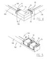
- FIG. 5 is a perspective view of two adjacent anchor clips attached to a wall of a facade coping system in accordance with the present invention.
- FIG. 6 is a perspective view of two adjacent anchor clips attached to a wall and a splice channel placed on one of the two anchor clips of a facade coping system in accordance with the present invention.
- FIG. 7 is a perspective view of two adjacent anchor clips attached to a wall and an end cap coping cover hooked on the two adjacent anchor clips of a facade coping system in accordance with the present invention.
- FIG. 8 is a perspective view of two anchor clips attached to a wall of a facade coping system in accordance with the present invention.
- FIG. 9 is a perspective view of an anchor clip attached to a wall shown in FIG. 8 and a splice channel placed on the anchor clip of a facade coping system in accordance with the present invention.
- FIG. 10 is a perspective view of an anchor clip attached to a wall of FIG. 9 , a splice channel placed on the anchor clip and a coping cover hooked on the anchor clip of a facade coping system in accordance with the present invention.
- FIG. 11 is a perspective view of two adjacent coping covers retained on an anchor clip and splice channel of a facade coping system in accordance with the present invention.
- FIG. 12 is a top view of a flat plane layout of a cover support of an anchor clip of a facade coping system in accordance with the present invention.
- FIG. 13 is a perspective view of an anchor clip of a facade coping system in accordance with the present invention.
- FIG. 14 is a front perspective view of a corner support clip of a facade coping system in accordance with the present invention.
- FIG. 15 is a rear perspective view of a corner support clip of a facade coping system in accordance with the present invention.
- FIG. 16 is an end view of a corner support clip of a facade coping system in accordance with the present invention.
- FIG. 17 is a cross sectional view of an anchor clip attached to a wall, a splice channel placed on the anchor clip and a coping cover retained on the anchor clip of a facade coping system in accordance with the present invention.
- the wall 100 includes a base portion 102 , a fastener stud 104 and a facade 106 .
- the facade coping system 1 preferably includes at least one anchor clip 10 and a coping cover 12 .
- the anchor clip 10 includes a clip support channel 14 , a cover support 16 and a spring support 18 .
- the clip support channel 14 includes a top member 20 , a first side member 22 and a second side member 24 .
- the first side member 22 extends downward from a first end of the top member 20 and the second side member 24 extends downward from a second end of the top member 20 .
- a bottom end of the first side member 22 is terminated with a first offset flange 26 and a bottom end of the second side member 24 is terminated with a second offset flange 28 .
- a plurality of first holes 30 are formed through the clip support channel 14 , adjacent a first side thereof and a plurality of second holes 32 are formed through the clip support channel, adjacent a second side thereof.
- the anchor clip 10 is attached to the fastener stud 104 by inserting a plurality of fasteners 25 through the first and second holes 30 , 32 and securing the plurality of fasteners 25 to the fastener stud 104 .
- the coping cover 12 includes a top surface 60 , a first side surface 62 and a second side surface 64 .
- the first side surface 60 extends downward from a first side of the top surface 60 and the second side surface 64 extends downward from a second side of the top surface 20 .
- a bottom end of the first side surface 62 is terminated with a first attachment clip 66 .
- a bottom end of the second side surface 64 is terminated with a second attachment clip 68 .
- the coping cover 12 is installed on the anchor clip 10 by hooking the second attachment clip 68 , under the second offset flange 28 .
- the first attachment clip 66 is pushed over the first end of the clip support channel 14 and below the first offset flange 26 , until the first attachment clip 66 hooks the first offset flange 26 .
- the spring support member 58 will pivot downward to allow the first attachment clip 66 to be pushed below the first offset flange 26 .
- the second portion 36 includes a second support member 48 , two second vertical members 50 and two second flange members 52 .
- the two second vertical members 50 are bent to extend downward from opposing sides of the second support member 48 .
- the two second flange members 52 are bent to extend outward from a bottom of the two second vertical members 50 .
- the first portion 34 is bent substantially perpendicular to the second portion 36 on the bend line 35 .
- the tabs 46 are secured to first vertical members 40 with any suitable attachment process, such as Lance Lock.
- the first portion 34 is attached to the top member 20 with any suitable attachment process, such as Lance Lock.
- the second portion 36 is attached to the second side member 24 .
- the spring support 18 preferably includes a spring base member 54 , spring vertical member 56 and a spring support member 58 .
- the vertical member 56 extends upward from the base member 54 and the spring support member 58 extends outward from spring vertical member 56 .
- the spring base member 54 is attached to the top member 20 , adjacent the first side member 22 with any suitable attachment process, such as Lance Lock.
- the coping cover 12 includes a top surface 60 , a first side surface 62 and a second side surface 64 .
- the first side surface 60 extends downward from a first side of the top surface 60 and the second side surface 64 extends downward from a second side of the top surface 20 .
- a bottom end of the first side surface 62 is terminated with a first attachment clip 66 .
- a bottom end of the second side member is terminated with a second attachment clip 68 .
- the coping cover 12 is installed on the anchor clip 10 by hooking the second attachment clip 68 , under the second offset flange 28 .
- the first attachment clip 66 is pushed over the first end of the clip support channel 14 and below the first offset flange 26 , until the first attachment clip 66 hooks the first offset flange 26 .
- the spring support member 58 will pivot downward to allow the first attachment clip 66 to be pushed below the first offset flange 26 .
- the facade coping system 1 also includes a splice channel 70 , a corner support clip 72 , a corner coping cover 74 and an end cap coping cover 76 .
- the splice channel 70 includes a top surface 78 , a first side surface 80 and a second side surface 82 .
- the first side surface 80 extends downward from a first side of the top surface 78 and the second side surface 82 extends downward from a second side of the top surface 78 .
- At least two rows of butyl sealant 84 are preferably applied to the top surface 78 .
- the butyl sealant 84 seals two adjacent coping covers 12 , 74 , 76 .
- the splice channel 70 is placed over the anchor clip 10 .
- a first coping cover 12 is secured to the anchor clip 10 with the splice channel 70 .
- a second coping cover 12 is attached to the anchor clip 10 with the splice channel 70 .
- the corner support clip 72 includes a corner base member 86 and a cover support member 88 .
- the corner base member 86 preferably includes a top member 90 , a ramp member 92 and a side member 94 .
- One end of the ramp member 92 extends upward from one end of the top member 90 and the side member 94 extends downward from the other end of the ramp member 92 .
- the side member 94 preferably includes a depressed area 96 , such that the coping covers 12 , 74 , 76 do not contact a middle of the side member 94 .
- a bottom of the side member 94 is terminated with an offset flange 98 .
- a plurality of first holes 110 are formed through the corner base member 86 , adjacent a first side thereof and a plurality of second holes 112 are formed through the corner base member 86 , adjacent a second side thereof.
- the cover support member 88 preferably includes a support member 114 , two vertical members 116 and two flange members 118 .
- the two first vertical members 116 are bent to extend downward from opposing sides of the support member 114 .
- the two flange members 118 are bent to extend outward from a bottom of the two vertical members 116 .
- the two flange members 118 are attached to a top of the top member 90 with any suitable attachment process, such as Lance Lock.
- the cover support member 72 is attached to a top of the fastener stud 104 by inserting a plurality of fasteners 75 through the first and second holes 110 , 112 and securing the plurality of fasteners 75 to the fastener stud 104 .
- the corner coping cover 74 includes two shortened coping covers 12 ′.
- a mitered end 120 is formed on one end of each shortened coping cover 12 ′.
- the mitered end is 45 degrees relative to a length of the shortened coping cover 12 ′.
- the mitered ends 120 are joined to each other with any suitable attachment process.
- Installing the corner coping cover 74 requires placing the splice channel 70 over the anchor clip 10 and inserting two anchor clips 10 into each open end of the corner coping cover 74 .
- the two anchor clips 10 are attached to the two fastener studs 104 with the plurality of fasteners 25 .
- the end cap coping cover 76 includes a shortened coping cover 12 ′′ and an end plate 122 .
- the end plate 122 is attached to one end of the shortened coping cover 12 ′′ with any suitable attachment method.
- two adjacent anchor clips 10 are attached to an end of the fastener stud 104 with a plurality of fasteners 25 .
- the splice channel 70 is placed on the anchor clip 10 , which is furthest away from an end of the wall 100 .
- the end coping cover 76 is attached to the two adjacent anchor clips 10 .
- the splice channel 70 seals a gap between the end cap coping cover 76 and a yet to be installed coping cover 12 .
Landscapes
- Engineering & Computer Science (AREA)
- Architecture (AREA)
- Civil Engineering (AREA)
- Structural Engineering (AREA)
- Life Sciences & Earth Sciences (AREA)
- Sustainable Development (AREA)
- Finishing Walls (AREA)
Abstract
Description
Claims (18)
Priority Applications (1)
| Application Number | Priority Date | Filing Date | Title |
|---|---|---|---|
| US14/252,183 US8978317B1 (en) | 2014-04-14 | 2014-04-14 | Coping for attachment to a wall with a non-structural exterior building facade |
Applications Claiming Priority (1)
| Application Number | Priority Date | Filing Date | Title |
|---|---|---|---|
| US14/252,183 US8978317B1 (en) | 2014-04-14 | 2014-04-14 | Coping for attachment to a wall with a non-structural exterior building facade |
Publications (1)
| Publication Number | Publication Date |
|---|---|
| US8978317B1 true US8978317B1 (en) | 2015-03-17 |
Family
ID=52632128
Family Applications (1)
| Application Number | Title | Priority Date | Filing Date |
|---|---|---|---|
| US14/252,183 Active US8978317B1 (en) | 2014-04-14 | 2014-04-14 | Coping for attachment to a wall with a non-structural exterior building facade |
Country Status (1)
| Country | Link |
|---|---|
| US (1) | US8978317B1 (en) |
Cited By (4)
| Publication number | Priority date | Publication date | Assignee | Title |
|---|---|---|---|---|
| US20150345143A1 (en) * | 2014-05-27 | 2015-12-03 | Omg, Inc. | Coping Cleat and System for Roof Blocking Unit |
| JP2018184748A (en) * | 2017-04-25 | 2018-11-22 | 株式会社ハウゼコ | Coping structural body |
| JP2024098316A (en) * | 2023-01-10 | 2024-07-23 | 積水ハウス株式会社 | Cap mounting structure |
| US12497777B1 (en) | 2024-02-01 | 2025-12-16 | Carlisle Construction Materials, LLC | Matching coping system for building panels |
Citations (12)
| Publication number | Priority date | Publication date | Assignee | Title |
|---|---|---|---|---|
| US3862531A (en) * | 1973-09-07 | 1975-01-28 | Miscellaneous Manufacturing Co | Coping structure |
| US4083158A (en) * | 1976-12-13 | 1978-04-11 | Philip L. Johnson | Coping mounting plate |
| US4550535A (en) * | 1983-07-21 | 1985-11-05 | Drogosch Edward J | Coping system |
| US4858406A (en) * | 1988-07-12 | 1989-08-22 | Metal Era, Inc. | Coping structure including rigid anchor bar |
| US5289662A (en) * | 1992-07-22 | 1994-03-01 | Castle Gary M | Wall coping system |
| US5893247A (en) * | 1998-01-13 | 1999-04-13 | W. P. Hickman Company | Coping |
| US6216408B1 (en) * | 2000-06-09 | 2001-04-17 | Petersen Aluminum Corporation | Coping assembly |
| US20050028464A1 (en) * | 2001-09-14 | 2005-02-10 | Metal-Era, Inc. | Coping assembly having a stone and mortar appearance |
| US20050235578A1 (en) * | 2004-04-22 | 2005-10-27 | Heidler Charles W Jr | Roof wall coping system and method |
| US7748173B1 (en) * | 2002-10-22 | 2010-07-06 | Inzeo Joseph A | Roof fascia with extension cleat |
| US8001739B1 (en) * | 2007-11-13 | 2011-08-23 | Metal-Era, Inc. | Parapet wall cover system |
| US8561367B2 (en) * | 2012-01-30 | 2013-10-22 | Robert John Kelly | Parapet vent |
-
2014
- 2014-04-14 US US14/252,183 patent/US8978317B1/en active Active
Patent Citations (13)
| Publication number | Priority date | Publication date | Assignee | Title |
|---|---|---|---|---|
| US3862531A (en) * | 1973-09-07 | 1975-01-28 | Miscellaneous Manufacturing Co | Coping structure |
| US4083158A (en) * | 1976-12-13 | 1978-04-11 | Philip L. Johnson | Coping mounting plate |
| US4550535A (en) * | 1983-07-21 | 1985-11-05 | Drogosch Edward J | Coping system |
| US4858406A (en) * | 1988-07-12 | 1989-08-22 | Metal Era, Inc. | Coping structure including rigid anchor bar |
| US5289662A (en) * | 1992-07-22 | 1994-03-01 | Castle Gary M | Wall coping system |
| US5893247A (en) * | 1998-01-13 | 1999-04-13 | W. P. Hickman Company | Coping |
| US6216408B1 (en) * | 2000-06-09 | 2001-04-17 | Petersen Aluminum Corporation | Coping assembly |
| US20050028464A1 (en) * | 2001-09-14 | 2005-02-10 | Metal-Era, Inc. | Coping assembly having a stone and mortar appearance |
| US7748173B1 (en) * | 2002-10-22 | 2010-07-06 | Inzeo Joseph A | Roof fascia with extension cleat |
| US20050235578A1 (en) * | 2004-04-22 | 2005-10-27 | Heidler Charles W Jr | Roof wall coping system and method |
| US7168209B2 (en) * | 2004-04-22 | 2007-01-30 | W.P. Hickman Systems, Inc. | Roof wall coping system and method |
| US8001739B1 (en) * | 2007-11-13 | 2011-08-23 | Metal-Era, Inc. | Parapet wall cover system |
| US8561367B2 (en) * | 2012-01-30 | 2013-10-22 | Robert John Kelly | Parapet vent |
Cited By (4)
| Publication number | Priority date | Publication date | Assignee | Title |
|---|---|---|---|---|
| US20150345143A1 (en) * | 2014-05-27 | 2015-12-03 | Omg, Inc. | Coping Cleat and System for Roof Blocking Unit |
| JP2018184748A (en) * | 2017-04-25 | 2018-11-22 | 株式会社ハウゼコ | Coping structural body |
| JP2024098316A (en) * | 2023-01-10 | 2024-07-23 | 積水ハウス株式会社 | Cap mounting structure |
| US12497777B1 (en) | 2024-02-01 | 2025-12-16 | Carlisle Construction Materials, LLC | Matching coping system for building panels |
Similar Documents
| Publication | Publication Date | Title |
|---|---|---|
| RU2504625C2 (en) | Ceiling with concealed suspension system and panels removable downwards | |
| US9677283B2 (en) | Building veneer system | |
| US8925273B2 (en) | Clips for thin brick wall system | |
| US9297168B2 (en) | Panel for wall of a set building and thereof construction method | |
| US8978317B1 (en) | Coping for attachment to a wall with a non-structural exterior building facade | |
| US3020988A (en) | Snap-in panel clip | |
| US10024062B2 (en) | Building veneer system | |
| US20240318434A1 (en) | Siding Attachment Accessory and Siding System | |
| US3347009A (en) | Selectively removable panel assembly | |
| KR101576230B1 (en) | Light weight steel frame assembly for ceiling finish | |
| WO2015088392A1 (en) | Suspended ventilated facade system for cladding buildings, subsystem for fastening cladding tiles, and cladding tile | |
| KR101566325B1 (en) | The aluminum insulation frame for architecture to easy assembling and thereof installation method | |
| KR101541382B1 (en) | Assembling type finishing panel for construction | |
| US20200063438A1 (en) | Ventilated thin brick panel system | |
| JP5166467B2 (en) | Handrail glass mounting device | |
| AU2024227669A1 (en) | Wall Cladding Starter Assembly | |
| KR101304825B1 (en) | Fixture for wall finishing panels | |
| CN103741927A (en) | Floor mounting structure | |
| JP5361366B2 (en) | Entrance fence fixing structure | |
| KR20240114970A (en) | Hanger type pannel and overlap install structure for non-calking of the same | |
| US20110078972A1 (en) | Siding Installation Spacer and Method of Installing Siding Using A Siding Installation Spacer | |
| RU148984U1 (en) | FACING FOR WALLS | |
| JP4099809B2 (en) | Brick wall and brick wall construction method | |
| RU2276243C1 (en) | Plinth profile set | |
| CA2867967C (en) | Building veneer system |
Legal Events
| Date | Code | Title | Description |
|---|---|---|---|
| AS | Assignment |
Owner name: METAL-ERA, WISCONSIN Free format text: ASSIGNMENT OF ASSIGNORS INTEREST;ASSIGNOR:INZEO, JOSEPH A., MR.;REEL/FRAME:032667/0639 Effective date: 20140414 |
|
| STCF | Information on status: patent grant |
Free format text: PATENTED CASE |
|
| MAFP | Maintenance fee payment |
Free format text: PAYMENT OF MAINTENANCE FEE, 4TH YR, SMALL ENTITY (ORIGINAL EVENT CODE: M2551); ENTITY STATUS OF PATENT OWNER: SMALL ENTITY Year of fee payment: 4 |
|
| AS | Assignment |
Owner name: ANTARES CAPITAL LP,AS COLLATERAL AGENT, ILLINOIS Free format text: SECURITY INTEREST;ASSIGNOR:METAL-ERA, LLC;REEL/FRAME:052431/0270 Effective date: 20200417 |
|
| AS | Assignment |
Owner name: METAL-ERA, LLC, WISCONSIN Free format text: ENTITY CONVERSION;ASSIGNOR:METAL-ERA, INC.;REEL/FRAME:052462/0107 Effective date: 20200416 |
|
| MAFP | Maintenance fee payment |
Free format text: PAYMENT OF MAINTENANCE FEE, 8TH YR, SMALL ENTITY (ORIGINAL EVENT CODE: M2552); ENTITY STATUS OF PATENT OWNER: SMALL ENTITY Year of fee payment: 8 |
|
| AS | Assignment |
Owner name: HICKMAN EDGE SYSTEMS LLC, WISCONSIN Free format text: RELEASE BY SECURED PARTY;ASSIGNOR:ANTARES CAPITAL LP;REEL/FRAME:067287/0001 Effective date: 20240501 Owner name: METAL-ERA, LLC, WISCONSIN Free format text: RELEASE BY SECURED PARTY;ASSIGNOR:ANTARES CAPITAL LP;REEL/FRAME:067287/0001 Effective date: 20240501 |
|
| AS | Assignment |
Owner name: CARLISLE CONSTRUCTION MATERIALS, LLC, PENNSYLVANIA Free format text: ASSIGNMENT OF ASSIGNORS INTEREST;ASSIGNORS:METAL-ERA, LLC;HICKMAN EDGE SYSTEMS LLC;REEL/FRAME:070281/0923 Effective date: 20241216 |