US8976522B2 - Portable electronic device and docking device thereof - Google Patents

Portable electronic device and docking device thereof Download PDF

Info

Publication number
US8976522B2
US8976522B2 US13/559,487 US201213559487A US8976522B2 US 8976522 B2 US8976522 B2 US 8976522B2 US 201213559487 A US201213559487 A US 201213559487A US 8976522 B2 US8976522 B2 US 8976522B2
Authority
US
United States
Prior art keywords
pivot
wedging
docking
touch display
frame
Prior art date
Legal status (The legal status is an assumption and is not a legal conclusion. Google has not performed a legal analysis and makes no representation as to the accuracy of the status listed.)
Active, expires
Application number
US13/559,487
Other versions
US20130176673A1 (en
Inventor
Chia-Lian Yen
Hua-Chung Tseng
Current Assignee (The listed assignees may be inaccurate. Google has not performed a legal analysis and makes no representation or warranty as to the accuracy of the list.)
Wistron Corp
Original Assignee
Wistron Corp
Priority date (The priority date is an assumption and is not a legal conclusion. Google has not performed a legal analysis and makes no representation as to the accuracy of the date listed.)
Filing date
Publication date
Application filed by Wistron Corp filed Critical Wistron Corp
Assigned to WISTRON CORP. reassignment WISTRON CORP. ASSIGNMENT OF ASSIGNORS INTEREST (SEE DOCUMENT FOR DETAILS). Assignors: TSENG, HUA-CHUNG, YEN, CHIA-LIAN
Publication of US20130176673A1 publication Critical patent/US20130176673A1/en
Application granted granted Critical
Publication of US8976522B2 publication Critical patent/US8976522B2/en
Active legal-status Critical Current
Adjusted expiration legal-status Critical

Links

Images

Classifications

    • GPHYSICS
    • G06COMPUTING OR CALCULATING; COUNTING
    • G06FELECTRIC DIGITAL DATA PROCESSING
    • G06F1/00Details not covered by groups G06F3/00 - G06F13/00 and G06F21/00
    • G06F1/16Constructional details or arrangements
    • G06F1/1613Constructional details or arrangements for portable computers
    • G06F1/1615Constructional details or arrangements for portable computers with several enclosures having relative motions, each enclosure supporting at least one I/O or computing function
    • G06F1/1616Constructional details or arrangements for portable computers with several enclosures having relative motions, each enclosure supporting at least one I/O or computing function with folding flat displays, e.g. laptop computers or notebooks having a clamshell configuration, with body parts pivoting to an open position around an axis parallel to the plane they define in closed position
    • G06F1/162Constructional details or arrangements for portable computers with several enclosures having relative motions, each enclosure supporting at least one I/O or computing function with folding flat displays, e.g. laptop computers or notebooks having a clamshell configuration, with body parts pivoting to an open position around an axis parallel to the plane they define in closed position changing, e.g. reversing, the face orientation of the screen with a two degrees of freedom mechanism, e.g. for folding into tablet PC like position or orienting towards the direction opposite to the user to show to a second user
    • GPHYSICS
    • G06COMPUTING OR CALCULATING; COUNTING
    • G06FELECTRIC DIGITAL DATA PROCESSING
    • G06F1/00Details not covered by groups G06F3/00 - G06F13/00 and G06F21/00
    • G06F1/16Constructional details or arrangements
    • G06F1/1613Constructional details or arrangements for portable computers
    • G06F1/1632External expansion units, e.g. docking stations

Definitions

  • the present invention relates to docking device, and in particular relates to a docking device for connection to a tablet computer.
  • Tablet computers are gradually becoming popular.
  • the tablet computer is usually operated via a touch screen disposed thereon.
  • the tablet computer can also be connected to a docking device, and operated via a keyboard, mouse or other interface devices.
  • the tablet computer is foxed to the docking device with an immobile mounting angle, and the mounting angle of the tablet computer therefore cannot be adjusted according to the demands of users.
  • a docking device for connection to a touch display device.
  • the docking device includes a docking body, a pivot unit and a frame.
  • the pivot unit is connected to the docking body.
  • the frame is connected to the pivot unit and pivoted relative to the docking body, wherein the touch display device is detachably disposed on the frame.
  • a portable electronic device in another embodiment, includes a touch display device and a docking device.
  • the docking device includes a docking body, a pivot unit and a frame.
  • the pivot unit is connected to the docking body.
  • the frame is connected to the pivot unit and pivoted relative to the docking body, wherein the touch display device is detachably disposed on the frame.
  • the touch display device (for example, tablet computer) can be pivoted on the docking device around the first pivot axis and the second pivot axis relative to the docking device to satisfy the operation demands of users.
  • FIG. 1 is an assembled view of the docking device of the embodiment of the invention.
  • FIGS. 2A to 2D show the touch display device pivoted on the docking device of the embodiment of the invention
  • FIG. 3 is an exploded view of the docking device of the embodiment of the invention.
  • FIG. 4 shows detailed structure of the docking device of the embodiment of the invention
  • FIG. 5A shows the wedging element of the docking device of the embodiment of the invention in the wedging position
  • FIG. 5B shows the wedging element of the docking device of the embodiment of the invention in the release position.
  • FIG. 1 shows a docking device 1 of an embodiment of the invention, which is adapted for connection to a touch display device 2 (with reference to FIG. 2A ).
  • the docking device 1 includes a docking body 10 , a pivot unit 20 , a frame 30 and an operation interface 40 .
  • the pivot unit 20 is connected to the docking body 10 .
  • the frame 30 is connected to the pivot unit 20 by a screw or other means, and is pivoted relative to the docking body 10 .
  • the touch display device 2 is detachably disposed on the frame 30 .
  • the operation interface 40 (for example, keyboard) is disposed on the docking body 10 .
  • the pivot unit 20 comprises a first pivot axis A 1 and a second pivot axis A 2 , and first pivot axis A 1 is perpendicular to the second pivot axis A 2 .
  • the touch display device 2 (for example, tablet computer) can be pivoted on the docking device 1 around the first pivot axis A 1 and the second pivot axis A 2 to satisfy the operation demands of users. For example, when the user inputs information into the touch display device 2 via the operation interface 40 , the touch display device 2 can be pivoted to the orientation as shown in FIG. 2A .
  • the user also can operate the touch display device 2 via the touch display thereof directly when the touch display device 2 is disposed on the docking device 1 , as shown in FIG.
  • the touch display device 2 can be rotated into the orientation as shown in FIG. 2D , wherein the touch display of the touch display device 2 faces the docking device 1 .
  • the pivot unit 20 comprises a first pivot element 21 and second pivot elements 22 .
  • the first pivot element 21 is connected to the docking body 10 .
  • the second pivot elements 22 are connected the frame 30 .
  • the second pivot elements 22 pivot on the first pivot element 21 .
  • the first pivot element 21 pivots around the first pivot axis A 1
  • second pivot elements 22 pivot around the second pivot axis A 2 .
  • the first pivot element 21 comprises a first section 211 and a second section 212 , the first section 211 is connected to the docking body 10 , the first section 211 is connected to the second section 212 , and the second pivot element 22 is disposed on the second section 212 .
  • the frame 30 comprises a frame body 31 , a wedging element 32 and an elastic element 33 , and the elastic element 33 is connected to the frame body 31 and the wedging element 32 .
  • the wedging element 32 comprises a hook 321 .
  • the wedging element 32 is moved between a wedging position ( FIG. 5A ) and a release position ( FIG. 5B ) relative to the frame body 31 .
  • the hook 321 of the wedging element 32 wedges the touch display device 2 .
  • the hook 321 of the wedging element 32 releases the touch display device 2 .
  • the elastic element 33 applies an elastic force upon the wedging element 32 to move the wedging element 32 back to the wedging position ( FIG. 5A ).
  • the elastic element 33 can be an extension spring or other springs.
  • the wedging element 32 further includes an elastic arm 322 .
  • the elastic arm 322 abuts a protrusion P inside the touch display device 2 to prevent the wedging element 32 from moved back to the wedging position by the elastic element 33 . Therefore, the user can detach the touch display device 2 form the docking device 1 with his/her single hand.
  • an opening 311 is formed on the frame body 31 , the wedging element 32 comprises a button 324 , and the button 324 is located in the opening 311 .
  • the wedging element 32 can be moved from the wedging position to the release position by pushing the button 324 .
  • the docking device 1 further comprises a touch display device connector 50 and a cable 51 .
  • the touch display device connector 50 and the cable 51 are disposed on the frame 30 to connect the touch display device 2 to an inner circuit of the docking device 1 .
  • the cable 51 passes through a central portion of the first section 211 .

Landscapes

  • Engineering & Computer Science (AREA)
  • Theoretical Computer Science (AREA)
  • Computer Hardware Design (AREA)
  • Physics & Mathematics (AREA)
  • Human Computer Interaction (AREA)
  • General Engineering & Computer Science (AREA)
  • General Physics & Mathematics (AREA)
  • Mathematical Physics (AREA)
  • Casings For Electric Apparatus (AREA)
  • Devices For Indicating Variable Information By Combining Individual Elements (AREA)
  • Pivots And Pivotal Connections (AREA)

Abstract

A docking device for connection to a touch display device is provided. The docking device includes a docking body, a pivot unit and a frame. The pivot unit is connected to the docking body. The frame is connected to the pivot unit and pivoted relative to the docking body, wherein the touch display device is detachably disposed on the frame.

Description

CROSS REFERENCE TO RELATED APPLICATIONS
This Application claims priority of Taiwan Patent Application No. 101100412, filed on Jan. 5, 2012, the entirety of which is incorporated by reference herein.
BACKGROUND OF THE INVENTION
1. Field of the Invention
The present invention relates to docking device, and in particular relates to a docking device for connection to a tablet computer.
2. Description of the Related Art
Tablet computers are gradually becoming popular. The tablet computer is usually operated via a touch screen disposed thereon. However, the tablet computer can also be connected to a docking device, and operated via a keyboard, mouse or other interface devices.
Conventionally, the tablet computer is foxed to the docking device with an immobile mounting angle, and the mounting angle of the tablet computer therefore cannot be adjusted according to the demands of users.
BRIEF SUMMARY OF THE INVENTION
In one embodiment of the invention, a docking device for connection to a touch display device is provided. The docking device includes a docking body, a pivot unit and a frame. The pivot unit is connected to the docking body. The frame is connected to the pivot unit and pivoted relative to the docking body, wherein the touch display device is detachably disposed on the frame.
In another embodiment of the invention, a portable electronic device is provided. The portable electronic device includes a touch display device and a docking device. The docking device includes a docking body, a pivot unit and a frame. The pivot unit is connected to the docking body. The frame is connected to the pivot unit and pivoted relative to the docking body, wherein the touch display device is detachably disposed on the frame.
Utilizing the docking device of the embodiment of the invention, the touch display device (for example, tablet computer) can be pivoted on the docking device around the first pivot axis and the second pivot axis relative to the docking device to satisfy the operation demands of users.
A detailed description is given in the following embodiments with reference to the accompanying drawings.
BRIEF DESCRIPTION OF THE DRAWINGS
The present invention can be more fully understood by reading the subsequent detailed description and examples with references made to the accompanying drawings, wherein:
FIG. 1 is an assembled view of the docking device of the embodiment of the invention;
FIGS. 2A to 2D show the touch display device pivoted on the docking device of the embodiment of the invention;
FIG. 3 is an exploded view of the docking device of the embodiment of the invention;
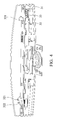
FIG. 4 shows detailed structure of the docking device of the embodiment of the invention;
FIG. 5A shows the wedging element of the docking device of the embodiment of the invention in the wedging position; and
FIG. 5B shows the wedging element of the docking device of the embodiment of the invention in the release position.
DETAILED DESCRIPTION OF THE INVENTION
The following description is of the best-contemplated mode of carrying out the invention. This description is made for the purpose of illustrating the general principles of the invention and should not be taken in a limiting sense. The scope of the invention is best determined by reference to the appended claims.
FIG. 1 shows a docking device 1 of an embodiment of the invention, which is adapted for connection to a touch display device 2 (with reference to FIG. 2A). The docking device 1 includes a docking body 10, a pivot unit 20, a frame 30 and an operation interface 40. The pivot unit 20 is connected to the docking body 10. The frame 30 is connected to the pivot unit 20 by a screw or other means, and is pivoted relative to the docking body 10. With reference to FIG. 2A, the touch display device 2 is detachably disposed on the frame 30. The operation interface 40 (for example, keyboard) is disposed on the docking body 10.
With reference to FIGS. 2A to 2D, the pivot unit 20 comprises a first pivot axis A1 and a second pivot axis A2, and first pivot axis A1 is perpendicular to the second pivot axis A2. The touch display device 2 (for example, tablet computer) can be pivoted on the docking device 1 around the first pivot axis A1 and the second pivot axis A2 to satisfy the operation demands of users. For example, when the user inputs information into the touch display device 2 via the operation interface 40, the touch display device 2 can be pivoted to the orientation as shown in FIG. 2A. The user also can operate the touch display device 2 via the touch display thereof directly when the touch display device 2 is disposed on the docking device 1, as shown in FIG. 2C. Additionally, when the user carries the docking device 1 and the touch display device 2 simultaneously, the touch display device 2 can be rotated into the orientation as shown in FIG. 2D, wherein the touch display of the touch display device 2 faces the docking device 1.
With reference to FIG. 3, the pivot unit 20 comprises a first pivot element 21 and second pivot elements 22. The first pivot element 21 is connected to the docking body 10. The second pivot elements 22 are connected the frame 30. The second pivot elements 22 pivot on the first pivot element 21. The first pivot element 21 pivots around the first pivot axis A1, and second pivot elements 22 pivot around the second pivot axis A2. The first pivot element 21 comprises a first section 211 and a second section 212, the first section 211 is connected to the docking body 10, the first section 211 is connected to the second section 212, and the second pivot element 22 is disposed on the second section 212.
With reference to FIGS. 3 and 4, the frame 30 comprises a frame body 31, a wedging element 32 and an elastic element 33, and the elastic element 33 is connected to the frame body 31 and the wedging element 32. The wedging element 32 comprises a hook 321.
With reference to FIGS. 5A and 5B, the wedging element 32 is moved between a wedging position (FIG. 5A) and a release position (FIG. 5B) relative to the frame body 31. When the wedging element 32 is in the wedging position (FIG. 5A), the hook 321 of the wedging element 32 wedges the touch display device 2. When the wedging element 32 is in the release position (FIG. 5B), the hook 321 of the wedging element 32 releases the touch display device 2. After the touch display device 2 is detached from the frame 30, the elastic element 33 applies an elastic force upon the wedging element 32 to move the wedging element 32 back to the wedging position (FIG. 5A). The elastic element 33 can be an extension spring or other springs. In this embodiment, the wedging element 32 further includes an elastic arm 322. With reference to FIG. 5B, when the wedging element 32 is being moved to the release position, the elastic arm 322 abuts a protrusion P inside the touch display device 2 to prevent the wedging element 32 from moved back to the wedging position by the elastic element 33. Therefore, the user can detach the touch display device 2 form the docking device 1 with his/her single hand.
With reference to FIG. 3, in the embodiment of the invention, an opening 311 is formed on the frame body 31, the wedging element 32 comprises a button 324, and the button 324 is located in the opening 311. The wedging element 32 can be moved from the wedging position to the release position by pushing the button 324.
With reference to FIG. 3, the docking device 1 further comprises a touch display device connector 50 and a cable 51. The touch display device connector 50 and the cable 51 are disposed on the frame 30 to connect the touch display device 2 to an inner circuit of the docking device 1. The cable 51 passes through a central portion of the first section 211.
Use of ordinal terms such as “first”, “second”, “third”, etc., in the claims to modify a claim element does not by itself connote any priority, precedence, or order of one claim element over another or the temporal order in which acts of a method are performed, but are used merely as labels to distinguish one claim element having a certain name from another element having a same name (but for use of the ordinal term) to distinguish the claim elements.
While the invention has been described by way of example and in terms of the preferred embodiments, it is to be understood that the invention is not limited to the disclosed embodiments. To the contrary, it is intended to cover various modifications and similar arrangements (as would be apparent to those skilled in the art). Therefore, the scope of the appended claims should be accorded the broadest interpretation so as to encompass all such modifications and similar arrangements.

Claims (17)

What is claimed is:
1. A docking device for connection to a touch display device, comprising:
a docking body;
a pivot unit, connected to the docking body; and
a frame, connected to the pivot unit and pivoted relative to the docking body, wherein the touch display device is detachably disposed on the frame,
wherein the frame comprises a frame body and a wedging element, and the wedging element is movable between a wedging position and a release position relative to the frame body, and when the wedging element is in the wedging position, the wedging element wedges the touch display device, and when the wedging element is in the release position, the wedging element releases the touch display device,
wherein the frame further comprises an elastic element, and the elastic element is connected to the frame body and the wedging element, and when the touch display device is detached from the frame, the elastic element applies an elastic force upon the wedging element to move the wedging element back to the wedging position,
wherein the wedging element further comprises an elastic arm, and when the wedging element is being moved to the release position, the elastic arm abuts the touch display device to prevent the wedging element from moving back to the wedging position.
2. The docking device as claimed in claim 1, wherein the pivot unit comprises a first pivot axis and a second pivot axis, and first pivot axis is perpendicular to the second pivot axis.
3. The docking device as claimed in claim 2, wherein the pivot unit comprises a first pivot element and at least one second pivot element, the first pivot element is connected to the docking body, the second pivot element is connected to the frame, the second pivot element pivots on the first pivot element, the first pivot element pivots around the first pivot axis, and second pivot element pivots around the second pivot axis.
4. The docking device as claimed in claim 3, wherein the first pivot element comprises a first section and a second section, the first section is connected to the docking body, the first section is connected to the second section, and the second pivot element is disposed on the second section.
5. The docking device as claimed in claim 1, wherein the wedging element comprises a hook, and the hook wedges the touch display device.
6. The docking device as claimed in claim 1, wherein an opening is formed on the frame body, and the wedging element comprises a button, and the button is located in the opening.
7. The docking device as claimed in claim 1, further comprising an operation interface disposed on the docking body.
8. The docking device as claimed in claim 1, further comprising a touch display device connector, disposed on the frame to be connected to the touch display device.
9. A portable electronic device, comprising:
a touch display device; and
a docking device, comprising:
a docking body;
a pivot unit, connected to the docking body; and
a frame, connected to the pivot unit and pivoted relative to the docking body, wherein the touch display device is detachably disposed on the frame,
wherein the frame comprises a frame body and a wedging element, and the wedging element is movable between a wedging position and a release position relative to the frame body, and when the wedging element is in the wedging position, the wedging element wedges the touch display device, and when the wedging element is in the release position, the wedging element releases the touch display device,
wherein the wedging element further comprises an elastic arm, and when the wedging element is being moved to the release position, the elastic arm abuts the touch display device to prevent the wedging element from moving back to the wedging position.
10. The portable electronic device as claimed in claim 9, wherein the pivot unit comprises a first pivot axis and a second pivot axis, and first pivot axis is perpendicular to the second pivot axis.
11. The portable electronic device as claimed in claim 10, wherein the pivot unit comprises a first pivot element and at least one second pivot element, the first pivot element is connected to the docking body, the second pivot element is connected to the frame, the second pivot element pivots on the first pivot element, the first pivot element pivots around the first pivot axis, and second pivot element pivots around the second pivot axis.
12. The portable electronic device as claimed in claim 11, wherein the first pivot element comprises a first section and a second section, the first section is connected to the docking body, the first section is connected to the second section, and the second pivot element is disposed on the second section.
13. The portable electronic device as claimed in claim 9, wherein the wedging element comprises a hook, and the hook wedges the touch display device.
14. The portable electronic device as claimed in claim 9, wherein the frame further comprises an elastic element, and the elastic element is connected to the frame body and the wedging element, and when the touch display device is detached from the frame, the elastic element applies an elastic force upon the wedging element to move the wedging element back to the wedging position.
15. The portable electronic device as claimed in claim 9, wherein an opening is formed on the frame body, and the wedging element comprises a button, and the button is located in the opening.
16. The portable electronic device as claimed in claim 9, wherein the docking device further comprises an operation interface disposed on the docking body.
17. The portable electronic device as claimed in claim 9, wherein the docking device further comprises a touch display device connector, disposed on the frame to be connected to the touch display device.
US13/559,487 2012-01-05 2012-07-26 Portable electronic device and docking device thereof Active 2033-05-06 US8976522B2 (en)

Applications Claiming Priority (3)

Application Number Priority Date Filing Date Title
TW101100412A 2012-01-05
TWTW101100412 2012-01-05
TW101100412A TWI454888B (en) 2012-01-05 2012-01-05 Portable electronic device and docking thereof

Publications (2)

Publication Number Publication Date
US20130176673A1 US20130176673A1 (en) 2013-07-11
US8976522B2 true US8976522B2 (en) 2015-03-10

Family

ID=48720394

Family Applications (1)

Application Number Title Priority Date Filing Date
US13/559,487 Active 2033-05-06 US8976522B2 (en) 2012-01-05 2012-07-26 Portable electronic device and docking device thereof

Country Status (3)

Country Link
US (1) US8976522B2 (en)
CN (1) CN103197732B (en)
TW (1) TWI454888B (en)

Cited By (4)

* Cited by examiner, † Cited by third party
Publication number Priority date Publication date Assignee Title
US20150153772A1 (en) * 2013-12-04 2015-06-04 Wistron Corp. Hand-held computer apparatus and accessory docking thereof
US20150245518A1 (en) * 2014-02-21 2015-08-27 Samsung Electronics Co., Ltd. Electronic device and electronic device included in a cover
US20150295303A1 (en) * 2014-04-14 2015-10-15 Compal Electronics, Inc. Electronic device having antenna structure
US20150370292A1 (en) * 2013-01-18 2015-12-24 Albiral Display Solutions, S.L. Retractable screen-and-keyboard assembly for tables

Families Citing this family (7)

* Cited by examiner, † Cited by third party
Publication number Priority date Publication date Assignee Title
USD701214S1 (en) * 2011-06-23 2014-03-18 Zagg Intellectual Property Holding Co., Inc. Support structure for portable electronic device
TWI509385B (en) * 2011-10-27 2015-11-21 Compal Electronics Inc Docking station
US9218025B2 (en) * 2012-09-11 2015-12-22 Logitech Europe S.A. Protective cover for a tablet computer
US10937013B2 (en) * 2013-01-13 2021-03-02 Retail Technologies Corporation Point of sale (POS) docking station system and method for a mobile tablet gun system with mobile tablet device
USD701511S1 (en) * 2013-09-06 2014-03-25 Shenzhen Xin Ni Da Technology Co., Ltd Stand and keyboard for tablet computer
TWI536143B (en) * 2014-08-27 2016-06-01 緯創資通股份有限公司 Adjustable docking device and display device therewith
CN220121233U (en) * 2023-06-08 2023-12-01 深圳市漫威互联网有限公司 Bluetooth keyboard with tablet personal computer protective housing

Citations (5)

* Cited by examiner, † Cited by third party
Publication number Priority date Publication date Assignee Title
TWM243698U (en) 2003-10-14 2004-09-11 First Int Computer Inc Assembly of panel computer which can be retrieved and turned over
TW200936013A (en) 2008-02-15 2009-08-16 Hon Hai Prec Ind Co Ltd Housing of foldable electronic device
TWM405716U (en) 2010-12-20 2011-06-11 Shin Zu Shing Co Ltd Automatic slanted hinge and portable electronic device
US20140111912A1 (en) * 2012-10-19 2014-04-24 Qnx Software Systems Limited Portable docking station for portable electronic device
US20140130303A1 (en) * 2012-11-15 2014-05-15 Acer Incorporated Hinge assembly and electronic device using the same

Family Cites Families (1)

* Cited by examiner, † Cited by third party
Publication number Priority date Publication date Assignee Title
KR101094767B1 (en) * 2010-05-19 2011-12-16 엘지전자 주식회사 Portable electronic devices

Patent Citations (5)

* Cited by examiner, † Cited by third party
Publication number Priority date Publication date Assignee Title
TWM243698U (en) 2003-10-14 2004-09-11 First Int Computer Inc Assembly of panel computer which can be retrieved and turned over
TW200936013A (en) 2008-02-15 2009-08-16 Hon Hai Prec Ind Co Ltd Housing of foldable electronic device
TWM405716U (en) 2010-12-20 2011-06-11 Shin Zu Shing Co Ltd Automatic slanted hinge and portable electronic device
US20140111912A1 (en) * 2012-10-19 2014-04-24 Qnx Software Systems Limited Portable docking station for portable electronic device
US20140130303A1 (en) * 2012-11-15 2014-05-15 Acer Incorporated Hinge assembly and electronic device using the same

Non-Patent Citations (1)

* Cited by examiner, † Cited by third party
Title
Taiwan Patent Office, Office Action, Patent Application Serial No. 101100412, May 12, 2014, Taiwan.

Cited By (8)

* Cited by examiner, † Cited by third party
Publication number Priority date Publication date Assignee Title
US20150370292A1 (en) * 2013-01-18 2015-12-24 Albiral Display Solutions, S.L. Retractable screen-and-keyboard assembly for tables
US9671834B2 (en) * 2013-01-18 2017-06-06 Albiral Display Solutions, S.L. Retractable screen-and-keyboard assembly for tables
US20150153772A1 (en) * 2013-12-04 2015-06-04 Wistron Corp. Hand-held computer apparatus and accessory docking thereof
US9367088B2 (en) * 2013-12-04 2016-06-14 Wistron Corp. Hand-held computer apparatus and accessory docking thereof
US20150245518A1 (en) * 2014-02-21 2015-08-27 Samsung Electronics Co., Ltd. Electronic device and electronic device included in a cover
US9661771B2 (en) * 2014-02-21 2017-05-23 Samsung Electronics Co., Ltd. Electronic device and electronic device included in a cover
US20150295303A1 (en) * 2014-04-14 2015-10-15 Compal Electronics, Inc. Electronic device having antenna structure
US9444128B2 (en) * 2014-04-14 2016-09-13 Compal Electronics, Inc. Electronic device having antenna structure

Also Published As

Publication number Publication date
TW201329673A (en) 2013-07-16
CN103197732B (en) 2016-03-16
TWI454888B (en) 2014-10-01
US20130176673A1 (en) 2013-07-11
CN103197732A (en) 2013-07-10

Similar Documents

Publication Publication Date Title
US8976522B2 (en) Portable electronic device and docking device thereof
JP6254314B2 (en) Connector assembly for electronic devices
KR102168145B1 (en) Hinge mechanism for rotatable component attachment
EP2560070B1 (en) Connection assembly for docking and composite electronic system
US9215818B2 (en) Electronic device and hinge structure thereof
US20130128432A1 (en) Portable electronic device
CN103425196A (en) Electronic device
US9568951B2 (en) Electronic device

Legal Events

Date Code Title Description
AS Assignment

Owner name: WISTRON CORP., TAIWAN

Free format text: ASSIGNMENT OF ASSIGNORS INTEREST;ASSIGNORS:YEN, CHIA-LIAN;TSENG, HUA-CHUNG;REEL/FRAME:028685/0407

Effective date: 20120705

STCF Information on status: patent grant

Free format text: PATENTED CASE

MAFP Maintenance fee payment

Free format text: PAYMENT OF MAINTENANCE FEE, 4TH YEAR, LARGE ENTITY (ORIGINAL EVENT CODE: M1551)

Year of fee payment: 4

MAFP Maintenance fee payment

Free format text: PAYMENT OF MAINTENANCE FEE, 8TH YEAR, LARGE ENTITY (ORIGINAL EVENT CODE: M1552); ENTITY STATUS OF PATENT OWNER: LARGE ENTITY

Year of fee payment: 8