US8972765B1 - Electrical energy management method and apparatus for multiple distribution buses and batteries - Google Patents
Electrical energy management method and apparatus for multiple distribution buses and batteries Download PDFInfo
- Publication number
- US8972765B1 US8972765B1 US13/439,752 US201213439752A US8972765B1 US 8972765 B1 US8972765 B1 US 8972765B1 US 201213439752 A US201213439752 A US 201213439752A US 8972765 B1 US8972765 B1 US 8972765B1
- Authority
- US
- United States
- Prior art keywords
- battery
- value
- power
- power source
- batteries
- Prior art date
- Legal status (The legal status is an assumption and is not a legal conclusion. Google has not performed a legal analysis and makes no representation as to the accuracy of the status listed.)
- Active, expires
Links
Images


Classifications
-
- H—ELECTRICITY
- H02—GENERATION; CONVERSION OR DISTRIBUTION OF ELECTRIC POWER
- H02J—CIRCUIT ARRANGEMENTS OR SYSTEMS FOR SUPPLYING OR DISTRIBUTING ELECTRIC POWER; SYSTEMS FOR STORING ELECTRIC ENERGY
- H02J7/00—Circuit arrangements for charging or depolarising batteries or for supplying loads from batteries
- H02J7/0029—Circuit arrangements for charging or depolarising batteries or for supplying loads from batteries with safety or protection devices or circuits
-
- H02J7/56—
Definitions
- the following disclosure relates generally to dynamically allocating power from a single power source to multiple batteries via independent buses, and specifically, optimally charging the multiple batteries via independent buses, protecting them from over and under charged conditions, protecting the single power source from fast transients and over current conditions, and allocating power between two or more independent distribution buses and their connected batteries.
- Electrically powered vehicles contain multiple independent electrical buses with separate batteries connected to loads on each bus.
- the buses supplied from a single fuel cell are not able to supply sufficient power for peak loads, nor can they respond quickly to load transients without suffering potential damage or degraded performance.
- a system in one embodiment disclosed herein, includes a power source, at least two electrical buses connected to the power source, and a battery connected to each one of the at least two electrical buses, each battery being charged by the power source, and each battery being connected to a load via one of the at least two electrical buses.
- a battery error signal generator for generating a battery error signal for each battery by finding a difference between a sensed battery voltage and a reference voltage.
- a reference control signal generator generates a reference control signal for each battery based on the battery error signals for each battery.
- a power sensor produces a sensed power signal between the power source and each battery connected to each of the two electrical buses. The reference control signal and the sensed power signal for each battery controls a power output value from the power source to each battery connected to each one of at least two electrical buses.
- a method for simultaneously distributing electrical power to at least two batteries connected on independent electrical buses to a central power source.
- the method includes determining a sensed battery voltage value for each battery and determining a battery error signal for each battery based on the difference between the sensed battery voltage value and a reference voltage value.
- a proportional battery power signal is determined for each battery based on the sensed battery voltage value for each battery and a sensed battery current value for each battery, and a reference control signal is generated for each battery based on a sensed power signal between the power source and each battery and one of the battery error signals for each battery and the proportional battery power signals for each battery.
- the power output from the power source to each battery is controlled based on the reference control signal for each battery.
- a method in another embodiment disclosed herein, includes measuring each battery voltage of a plurality of batteries connected to a single power source via independent electrical buses, and measuring each battery current of the plurality of batteries.
- a battery error signal is generated for each battery of the plurality of batteries by the determining a difference between each battery voltage value and a reference voltage value. If the sum of all battery error signals for the plurality of batteries is greater than a maximum power value of a power source used to charge the plurality of batteries, then a reference control signal is generated for each battery of the plurality of batteries based on determining if the sum of all battery error signals for the plurality of batteries is greater than a maximum power value of a power source used to charge the plurality of batteries. The power output is controlled from the power source to each battery of the plurality of batteries based on the reference control signal.
- the embodiments disclosed herein dynamically allocate power to multiple batteries and their buses from a single power source, whereas other identified solutions charge only one battery or lack the ability to recharge onboard batteries entirely.
- the embodiments disclosed herein allow greater system redundancy and reliability through fault isolation and multiple energy storage elements. A fault or battery failure on one bus can be easily isolated from the other, and minimum additional components can allow loads and batteries to be connected or disconnected in various configurations to route around faults.
- FIG. 1 is a schematic diagram in accordance with an embodiment disclosed herein.
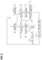
- FIG. 2 is a schematic diagram of further detailing the Partition FX 20 of FIG. 1 .
- FIG. 3 is a logical flowchart process in accordance with an embodiment disclosed herein.
- the following disclosure describes a system and method for dynamically allocating power to multiple batteries via their respective buses from a single power source.
- Electrically powered vehicles often contain at least two independent electrical buses with separate batteries on each bus. These buses are supplied from a single power source, such as a fuel cell, which will not alone supply sufficient power for peak loads, nor will it respond quickly to load transients without suffering potential damage or having a degraded performance.
- a single power source such as a fuel cell
- the embodiments disclosed below include multiple batteries connected to a load to serve as an energy buffer which supplies peak power to the loads when the power source is insufficient to do so, and to prevent load transients from propagating to the fuel cell.
- Each battery includes a control loop which controls battery recharging and generates a reference control signal configured to direct up to full power source generation capability to each respective electrical bus.
- FIG. 1 is a schematic diagram illustrating a system configured to include a power source 10 .
- the power source 10 may comprise a fuel cell or any other electrical power generation device.
- the power source in FIG. 1 is connected to two independent electrical buses, 11 A and 11 B, used to charge batteries 14 A and 14 B, respectively. Although only two buses are shown for simplification purposes, many more buses may be incorporated into this embodiment. However, it is important for each electrical bus be discretely connected to a battery for charging and supplying power to an associated load.
- a DC to DC converter 12 A and 12 B is connected between the power source 10 and each battery 14 A and 14 B via each the electrical bus 11 A and 11 B.
- the DC to DC converters 12 A and 12 B allow for each electrical bus 11 A and 11 B to be controlled by a converter control signal ( 50 A and 50 B, described below) to regulate an independent voltage level output requirement which may be different from the power supplied by the power source 10 .
- a load or loads may be applied to the output of each electrical bus 11 A and 11 B to receive power from the respective batteries 14 A and 14 B and/or power from the power source 10 .
- proportional-integral-derivative controllers (PID controllers) #2b at 18 B and #2a at 18 A take the measured voltage for each battery from the voltage sensors 16 A and 16 B with a reference voltage Vref to output a battery error signal PREF_A′ for battery A at 14 A, and a battery error signal PREF_B′ for battery B at 14 B.
- the PID controllers are a generic control loop feedback mechanism configured to calculate an “error” value output as the difference between a measured process variable, here the realtime voltage measurement, and a desired setpoint, Vref. All three sets of these signals, from the current sensors 15 A and 15 B, the voltage sensors 16 A and 16 B and the PID controllers 18 A and 18 B are feed into the block in FIG. 1 denoted as Partition FX 20 .
- the Partition FX 20 is described further in detail in FIG. 2 .
- Each of the above-identified signals feed into the Partition FX 20 are used to output a reference control signals PREF_A and PREF_B with respect to each battery.
- two reference control signals PREF_A and PREF_B are output and used to provide a converter control signal 50 A and 50 B to the DC to DC converters 12 A and 12 B, respectively, for each battery's electrical bus.
- a power source 10 is connected to at least two electrical buses 11 A and 11 B.
- Batteries 14 A and 14 B are connected to each one of the at least two electrical buses 11 A and 11 B, where each battery 14 A and 14 B are charged by the power source 10 , and are connected to a load, (not shown, between Out+ and Out ⁇ ), via one of the at least two electrical buses 11 A and 11 B.
- a battery error signal generator 18 A and 18 B generates a battery error signal PREF_A′ and PREF_B′ for each battery 14 A and 14 B by finding a difference between a sensed battery voltage and a reference voltage Vref.
- a reference control signal generator 20 generates a reference control signal PREF_A and PREF_B for each battery based on the battery error signals PREF_A′ and PREF_B′ for each battery 14 A and 14 B.
- Power sensors 24 A and 24 B produces a sensed power signal between the power source 10 and each battery 14 A and 14 B connected to each one of the at least two electrical buses 11 A and 11 B.
- the reference control signal for each battery PREF_A and PREF_B and the sensed power signal for each battery produce a converter control signal 50 A and 50 B to control a power output value from the power source 10 to each battery 14 A and 14 B on their respective electrical buses 11 A and 11 B, by controlling each DC to DC converter 12 A and 12 B, respectively.
- the battery error signals PREF_A′ and PREF_B′ are passed through multiplexer 26 and each battery error signal value is output as the reference control signal PREF_A and PREF_B, respectively.
- the battery errors signals PREF_A′ and PREF_B′ are passed through to the inner control loops as shown in FIG. 1 .
- a proportional battery power signal needs to be determined based on the sensed voltage and current signals.
- the battery terminal voltage Va and Vb and current Ia and Ib of each battery are monitored and used to calculate the State of Charge (S.O.C.) of each battery.
- the sensed current values Ia and Ib from current sensors 15 A and 15 B, and the sensed battery terminal voltage values Va and Vb from voltage sensors 16 A and 16 B are feed into S.O.C. calculators, 30 A and 30 B, respectively.
- the State of Charge estimation may be accomplished in many different methods. The following is one example where only Ia and Ib are required to calculate the State of Charge for each battery 14 A and 14 B:
- the S.O.C. is then adjusted at 32 A and 32 B to produce an adjusted S.O.C. value including a capacity fade value calculated as:
- S . O . C . ⁇ Adjusted Capacity 0 ( 1 - ⁇ 0 t ⁇ I Battery ⁇ ( t ) ⁇ ⁇ d t C Current )
- Capacity 0 is the value of the total charge capacity of a new battery
- C Current is the capacity of the current battery less than Capacity 0 based on charge degradation due to battery usage.
- the calculated S.O.C. should be divided by the actual current battery capacity.
- the S.O.D. of each battery is added to compute a total S.O.D. at 36 , and each battery S.O.D. is divided by the total S.O.D. at 38 A and 38 B to determine a per battery power ratio based on the total S.O.D.
- the per battery power ratio is multiplied by the maximum power Pmax 40 A and 40 B of the power source 10 to generate proportional battery power signals PREF_A′′ and PREF_B′′.
- This information is used when the sum of the power references exceed the maximum allowable power by allocating more power to the bus with the battery which is more deeply discharged.
- the power is allocated per battery as a fraction of the maximum allowed power equal to the S.O.D. of the battery divided by the total S.O.D. of all batteries. This ensures that as each battery discharges further, each battery is allocated a larger portion of the available power.
- a method of simultaneously distributing electrical power to at least two batteries 14 A and 14 B connected on independent electrical buses 11 A and 11 B to a central power source 10 includes determining a sensed battery voltage value at 16 A and 16 B for each battery, and determining battery error signals PREF_A′ and PREF_B′ for each battery based on the difference between the sensed battery voltage value and a reference voltage value Vref.
- a proportional battery power signal PREF_A′′ and PREF_B′′ is determined for each battery based on the sensed battery voltage value for each battery and a sensed battery current value for each battery.
- a converter control signal 50 A and 50 B is generated for each battery based on a sensed power signal at 24 A and 24 B between the power source 10 and each battery 14 A and 14 B and the reference control signals PREF_A and PREF_B for each battery.
- the power output from the power source 10 is controlled to each battery based on the converter control signals for each battery.
- FIG. 3 is a logical flowchart process illustrating a method of generating a converter control signal for each electrical bus and follows the control signal paths of FIG. 2 .
- a measurement of battery terminal voltages Va and Vb are made at 300 and battery error signals PREF_A′ and PREF_B′ are generated by a PID controller from the voltage values by finding the difference between each measured battery terminal voltage value Va and Vb from a reference voltage signal Vref 302 at 304 .
- Both battery error signal values of PREF_A′ and PREF_B′ are added together and compared to a maximum power value Pmax 306 .
- each battery error signal is output 308 as PREF_A and PREF_B, respectively, from the multiplexer 26 .
- each battery current measurement Ia and Ib at 310 and each battery terminal voltage measurement Va and Vb from 300 are input into a State of Charge (S.O.C.) calculation to determine each battery's S.O.C. 312 .
- Each battery's S.O.C. is then adjusted for a capacity fade value at 314 , and t adjusted S.O.C. value for each battery is then used to calculate a State of Discharge (S.O.D.) value for each battery by subtracting the adjusted S.O.C. value from a value of one (1), 316 .
- the output reference control signal is then determined as a per battery allocation of power as a fraction per battery of the maximum allowed power (Pmax) equal to the S.O.D. of each battery divided by the total S.O.D. of all the batteries 318 .
- an embodiment presented herein includes a method configured to measure each battery voltage 300 of a plurality of batteries connected to a single power source via independent electrical buses, and measures each battery current 310 of the plurality of batteries.
- a battery error signal is generated 302 for each battery of the plurality of batteries by the determining a difference between each battery terminal voltage value Va and Vb and a reference voltage value Vref.
- the sum of all battery error signals for the plurality of batteries is determined if it is greater 306 than a maximum power value of a power source used to charge the plurality of batteries.
- a reference control signal is generated 308 / 318 for each battery of the plurality of batteries based on determining if the sum of all battery error signals for the plurality of batteries is greater than a maximum power value of a power source used to charge the plurality of batteries. The power output from the power source to each battery of the plurality of batteries is then controlled based on the generated reference control signal.
- the concepts described herein dynamically allocate power to multiple batteries/buses from a single power source, whereas other identified solutions charge only one battery at a time. This allows greater system redundancy and reliability through fault isolation and multiple energy storage elements.
- a fault or battery failure on one bus can be easily isolated from the other based on the voltage and current sensing capabilities at the batteries and minimum additional components can allow loads and batteries to be connected or disconnected in various configurations to route around faults.
Landscapes
- Engineering & Computer Science (AREA)
- Power Engineering (AREA)
- Charge And Discharge Circuits For Batteries Or The Like (AREA)
Abstract
Description
where Capacity is the amount of charge stored in a fully charged battery. (Battery terminal voltage values Va and Vb are not required for this particular method, but may be required for alternative and more sophisticated methods not disclosed herein.)
where Capacity0 is the value of the total charge capacity of a new battery, and CCurrent is the capacity of the current battery less than Capacity0 based on charge degradation due to battery usage. What the calculation of S.O.C.Adjusted accomplishes the allocation of more charging power to a battery which is mostly discharged. The S.O.C.Adjusted determines how much charge is in a battery compared to the maximum amount of charge the battery is able to store. As a battery ages, the amount of charge it is able to store decreases. Thus, if a S.O.C. is calculated for an old battery that is fully charged using the capacity of a new battery, the calculated S.O.C. will indicate a less than fully charged battery. In order to compensate for this, the calculated S.O.C. should be divided by the actual current battery capacity.
S.O.D.=1−S.O.C.Adjusted
Claims (20)
Priority Applications (1)
| Application Number | Priority Date | Filing Date | Title |
|---|---|---|---|
| US13/439,752 US8972765B1 (en) | 2012-04-04 | 2012-04-04 | Electrical energy management method and apparatus for multiple distribution buses and batteries |
Applications Claiming Priority (1)
| Application Number | Priority Date | Filing Date | Title |
|---|---|---|---|
| US13/439,752 US8972765B1 (en) | 2012-04-04 | 2012-04-04 | Electrical energy management method and apparatus for multiple distribution buses and batteries |
Publications (1)
| Publication Number | Publication Date |
|---|---|
| US8972765B1 true US8972765B1 (en) | 2015-03-03 |
Family
ID=52575229
Family Applications (1)
| Application Number | Title | Priority Date | Filing Date |
|---|---|---|---|
| US13/439,752 Active 2033-03-09 US8972765B1 (en) | 2012-04-04 | 2012-04-04 | Electrical energy management method and apparatus for multiple distribution buses and batteries |
Country Status (1)
| Country | Link |
|---|---|
| US (1) | US8972765B1 (en) |
Cited By (54)
| Publication number | Priority date | Publication date | Assignee | Title |
|---|---|---|---|---|
| US20140265606A1 (en) * | 2013-03-14 | 2014-09-18 | Solaredge Technologies Ltd. | Method and apparatus for storing and depleting energy |
| US20160311328A1 (en) * | 2015-04-21 | 2016-10-27 | Samsung Electronics Co., Ltd. | Battery control method and apparatus, battery module, and battery pack |
| US9543889B2 (en) | 2006-12-06 | 2017-01-10 | Solaredge Technologies Ltd. | Distributed power harvesting systems using DC power sources |
| US20170040915A1 (en) * | 2015-08-04 | 2017-02-09 | The Boeing Company | Parallel modular converter architecture for efficient ground electric vehicles |
| US9639106B2 (en) | 2012-03-05 | 2017-05-02 | Solaredge Technologies Ltd. | Direct current link circuit |
| US20170212171A1 (en) * | 2016-01-26 | 2017-07-27 | Gs Yuasa International Ltd. | State estimation device, energy storage module, vehicle, and state estimation method |
| US9812984B2 (en) | 2012-01-30 | 2017-11-07 | Solaredge Technologies Ltd. | Maximizing power in a photovoltaic distributed power system |
| US9853538B2 (en) | 2007-12-04 | 2017-12-26 | Solaredge Technologies Ltd. | Distributed power harvesting systems using DC power sources |
| US9853490B2 (en) | 2006-12-06 | 2017-12-26 | Solaredge Technologies Ltd. | Distributed power system using direct current power sources |
| US9853565B2 (en) | 2012-01-30 | 2017-12-26 | Solaredge Technologies Ltd. | Maximized power in a photovoltaic distributed power system |
| US9866098B2 (en) | 2011-01-12 | 2018-01-09 | Solaredge Technologies Ltd. | Serially connected inverters |
| US9869701B2 (en) | 2009-05-26 | 2018-01-16 | Solaredge Technologies Ltd. | Theft detection and prevention in a power generation system |
| US9876430B2 (en) | 2008-03-24 | 2018-01-23 | Solaredge Technologies Ltd. | Zero voltage switching |
| US9935458B2 (en) | 2010-12-09 | 2018-04-03 | Solaredge Technologies Ltd. | Disconnection of a string carrying direct current power |
| US9948233B2 (en) | 2006-12-06 | 2018-04-17 | Solaredge Technologies Ltd. | Distributed power harvesting systems using DC power sources |
| US9960731B2 (en) | 2006-12-06 | 2018-05-01 | Solaredge Technologies Ltd. | Pairing of components in a direct current distributed power generation system |
| US9966766B2 (en) | 2006-12-06 | 2018-05-08 | Solaredge Technologies Ltd. | Battery power delivery module |
| US9979280B2 (en) | 2007-12-05 | 2018-05-22 | Solaredge Technologies Ltd. | Parallel connected inverters |
| US10061957B2 (en) | 2016-03-03 | 2018-08-28 | Solaredge Technologies Ltd. | Methods for mapping power generation installations |
| US10097007B2 (en) | 2006-12-06 | 2018-10-09 | Solaredge Technologies Ltd. | Method for distributed power harvesting using DC power sources |
| US10116217B2 (en) | 2007-08-06 | 2018-10-30 | Solaredge Technologies Ltd. | Digital average input current control in power converter |
| US10230310B2 (en) | 2016-04-05 | 2019-03-12 | Solaredge Technologies Ltd | Safety switch for photovoltaic systems |
| US10381977B2 (en) | 2012-01-30 | 2019-08-13 | Solaredge Technologies Ltd | Photovoltaic panel circuitry |
| US10396662B2 (en) | 2011-09-12 | 2019-08-27 | Solaredge Technologies Ltd | Direct current link circuit |
| US10461687B2 (en) | 2008-12-04 | 2019-10-29 | Solaredge Technologies Ltd. | Testing of a photovoltaic panel |
| US10468878B2 (en) | 2008-05-05 | 2019-11-05 | Solaredge Technologies Ltd. | Direct current power combiner |
| US10599113B2 (en) | 2016-03-03 | 2020-03-24 | Solaredge Technologies Ltd. | Apparatus and method for determining an order of power devices in power generation systems |
| US10651647B2 (en) | 2013-03-15 | 2020-05-12 | Solaredge Technologies Ltd. | Bypass mechanism |
| US10673229B2 (en) | 2010-11-09 | 2020-06-02 | Solaredge Technologies Ltd. | Arc detection and prevention in a power generation system |
| US10673222B2 (en) | 2010-11-09 | 2020-06-02 | Solaredge Technologies Ltd. | Arc detection and prevention in a power generation system |
| US10931119B2 (en) | 2012-01-11 | 2021-02-23 | Solaredge Technologies Ltd. | Photovoltaic module |
| US10931228B2 (en) | 2010-11-09 | 2021-02-23 | Solaredge Technologies Ftd. | Arc detection and prevention in a power generation system |
| US11018623B2 (en) | 2016-04-05 | 2021-05-25 | Solaredge Technologies Ltd. | Safety switch for photovoltaic systems |
| US11031861B2 (en) | 2006-12-06 | 2021-06-08 | Solaredge Technologies Ltd. | System and method for protection during inverter shutdown in distributed power installations |
| US11081608B2 (en) | 2016-03-03 | 2021-08-03 | Solaredge Technologies Ltd. | Apparatus and method for determining an order of power devices in power generation systems |
| US11177663B2 (en) | 2016-04-05 | 2021-11-16 | Solaredge Technologies Ltd. | Chain of power devices |
| US11177768B2 (en) | 2012-06-04 | 2021-11-16 | Solaredge Technologies Ltd. | Integrated photovoltaic panel circuitry |
| US11264947B2 (en) | 2007-12-05 | 2022-03-01 | Solaredge Technologies Ltd. | Testing of a photovoltaic panel |
| US11296650B2 (en) | 2006-12-06 | 2022-04-05 | Solaredge Technologies Ltd. | System and method for protection during inverter shutdown in distributed power installations |
| US11309832B2 (en) | 2006-12-06 | 2022-04-19 | Solaredge Technologies Ltd. | Distributed power harvesting systems using DC power sources |
| US11569659B2 (en) | 2006-12-06 | 2023-01-31 | Solaredge Technologies Ltd. | Distributed power harvesting systems using DC power sources |
| US11569660B2 (en) | 2006-12-06 | 2023-01-31 | Solaredge Technologies Ltd. | Distributed power harvesting systems using DC power sources |
| US11598652B2 (en) | 2006-12-06 | 2023-03-07 | Solaredge Technologies Ltd. | Monitoring of distributed power harvesting systems using DC power sources |
| US11687112B2 (en) | 2006-12-06 | 2023-06-27 | Solaredge Technologies Ltd. | Distributed power harvesting systems using DC power sources |
| US11728768B2 (en) | 2006-12-06 | 2023-08-15 | Solaredge Technologies Ltd. | Pairing of components in a direct current distributed power generation system |
| US11735910B2 (en) | 2006-12-06 | 2023-08-22 | Solaredge Technologies Ltd. | Distributed power system using direct current power sources |
| US11855231B2 (en) | 2006-12-06 | 2023-12-26 | Solaredge Technologies Ltd. | Distributed power harvesting systems using DC power sources |
| US11881814B2 (en) | 2005-12-05 | 2024-01-23 | Solaredge Technologies Ltd. | Testing of a photovoltaic panel |
| US11888387B2 (en) | 2006-12-06 | 2024-01-30 | Solaredge Technologies Ltd. | Safety mechanisms, wake up and shutdown methods in distributed power installations |
| US12032080B2 (en) | 2006-12-06 | 2024-07-09 | Solaredge Technologies Ltd. | Safety mechanisms, wake up and shutdown methods in distributed power installations |
| US12057807B2 (en) | 2016-04-05 | 2024-08-06 | Solaredge Technologies Ltd. | Chain of power devices |
| US12418177B2 (en) | 2009-10-24 | 2025-09-16 | Solaredge Technologies Ltd. | Distributed power system using direct current power sources |
| US20250296692A1 (en) * | 2023-07-10 | 2025-09-25 | Archer Aviation Inc. | Systems and methods for aircraft energy optimization |
| US12500436B2 (en) * | 2021-10-20 | 2025-12-16 | China Energy Investment Corporation Limited | Controller, system, and method for managing discharge or charge of heterogeneous battery packs |
Citations (6)
| Publication number | Priority date | Publication date | Assignee | Title |
|---|---|---|---|---|
| US6901520B2 (en) * | 2000-02-16 | 2005-05-31 | International Business Machines Corporation | Power supply protection apparatus for computer system |
| US7465507B2 (en) | 2004-09-21 | 2008-12-16 | Genesis Fueltech, Inc. | Portable fuel cell system with releasable and rechargeable batteries |
| US7745025B2 (en) | 2006-02-14 | 2010-06-29 | Mti Microfuel Cells Inc. | Fuel cell based rechargable power pack system and associated methods for controlling same |
| US7847432B2 (en) * | 2006-04-24 | 2010-12-07 | Toyota Jidosha Kabushiki Kaisha | Power supply system and vehicle |
| US20120212176A1 (en) * | 2011-02-21 | 2012-08-23 | Jong-Doo Park | Battery management system |
| US20130082664A1 (en) * | 2010-06-25 | 2013-04-04 | Tatsuki HIRAOKA | Charging method and charging system for lithium ion secondary battery |
-
2012
- 2012-04-04 US US13/439,752 patent/US8972765B1/en active Active
Patent Citations (6)
| Publication number | Priority date | Publication date | Assignee | Title |
|---|---|---|---|---|
| US6901520B2 (en) * | 2000-02-16 | 2005-05-31 | International Business Machines Corporation | Power supply protection apparatus for computer system |
| US7465507B2 (en) | 2004-09-21 | 2008-12-16 | Genesis Fueltech, Inc. | Portable fuel cell system with releasable and rechargeable batteries |
| US7745025B2 (en) | 2006-02-14 | 2010-06-29 | Mti Microfuel Cells Inc. | Fuel cell based rechargable power pack system and associated methods for controlling same |
| US7847432B2 (en) * | 2006-04-24 | 2010-12-07 | Toyota Jidosha Kabushiki Kaisha | Power supply system and vehicle |
| US20130082664A1 (en) * | 2010-06-25 | 2013-04-04 | Tatsuki HIRAOKA | Charging method and charging system for lithium ion secondary battery |
| US20120212176A1 (en) * | 2011-02-21 | 2012-08-23 | Jong-Doo Park | Battery management system |
Cited By (134)
| Publication number | Priority date | Publication date | Assignee | Title |
|---|---|---|---|---|
| US11881814B2 (en) | 2005-12-05 | 2024-01-23 | Solaredge Technologies Ltd. | Testing of a photovoltaic panel |
| US10230245B2 (en) | 2006-12-06 | 2019-03-12 | Solaredge Technologies Ltd | Battery power delivery module |
| US10637393B2 (en) | 2006-12-06 | 2020-04-28 | Solaredge Technologies Ltd. | Distributed power harvesting systems using DC power sources |
| US12316274B2 (en) | 2006-12-06 | 2025-05-27 | Solaredge Technologies Ltd. | Pairing of components in a direct current distributed power generation system |
| US12281919B2 (en) | 2006-12-06 | 2025-04-22 | Solaredge Technologies Ltd. | Monitoring of distributed power harvesting systems using DC power sources |
| US12276997B2 (en) | 2006-12-06 | 2025-04-15 | Solaredge Technologies Ltd. | Distributed power harvesting systems using DC power sources |
| US12224706B2 (en) | 2006-12-06 | 2025-02-11 | Solaredge Technologies Ltd. | Pairing of components in a direct current distributed power generation system |
| US12107417B2 (en) | 2006-12-06 | 2024-10-01 | Solaredge Technologies Ltd. | Distributed power harvesting systems using DC power sources |
| US12068599B2 (en) | 2006-12-06 | 2024-08-20 | Solaredge Technologies Ltd. | System and method for protection during inverter shutdown in distributed power installations |
| US11063440B2 (en) | 2006-12-06 | 2021-07-13 | Solaredge Technologies Ltd. | Method for distributed power harvesting using DC power sources |
| US9853490B2 (en) | 2006-12-06 | 2017-12-26 | Solaredge Technologies Ltd. | Distributed power system using direct current power sources |
| US11043820B2 (en) | 2006-12-06 | 2021-06-22 | Solaredge Technologies Ltd. | Battery power delivery module |
| US12046940B2 (en) | 2006-12-06 | 2024-07-23 | Solaredge Technologies Ltd. | Battery power control |
| US12032080B2 (en) | 2006-12-06 | 2024-07-09 | Solaredge Technologies Ltd. | Safety mechanisms, wake up and shutdown methods in distributed power installations |
| US11031861B2 (en) | 2006-12-06 | 2021-06-08 | Solaredge Technologies Ltd. | System and method for protection during inverter shutdown in distributed power installations |
| US12027849B2 (en) | 2006-12-06 | 2024-07-02 | Solaredge Technologies Ltd. | Distributed power system using direct current power sources |
| US9948233B2 (en) | 2006-12-06 | 2018-04-17 | Solaredge Technologies Ltd. | Distributed power harvesting systems using DC power sources |
| US9960731B2 (en) | 2006-12-06 | 2018-05-01 | Solaredge Technologies Ltd. | Pairing of components in a direct current distributed power generation system |
| US9966766B2 (en) | 2006-12-06 | 2018-05-08 | Solaredge Technologies Ltd. | Battery power delivery module |
| US11728768B2 (en) | 2006-12-06 | 2023-08-15 | Solaredge Technologies Ltd. | Pairing of components in a direct current distributed power generation system |
| US11296650B2 (en) | 2006-12-06 | 2022-04-05 | Solaredge Technologies Ltd. | System and method for protection during inverter shutdown in distributed power installations |
| US11962243B2 (en) | 2006-12-06 | 2024-04-16 | Solaredge Technologies Ltd. | Method for distributed power harvesting using DC power sources |
| US11961922B2 (en) | 2006-12-06 | 2024-04-16 | Solaredge Technologies Ltd. | Distributed power harvesting systems using DC power sources |
| US11309832B2 (en) | 2006-12-06 | 2022-04-19 | Solaredge Technologies Ltd. | Distributed power harvesting systems using DC power sources |
| US10097007B2 (en) | 2006-12-06 | 2018-10-09 | Solaredge Technologies Ltd. | Method for distributed power harvesting using DC power sources |
| US11476799B2 (en) | 2006-12-06 | 2022-10-18 | Solaredge Technologies Ltd. | Distributed power harvesting systems using DC power sources |
| US11888387B2 (en) | 2006-12-06 | 2024-01-30 | Solaredge Technologies Ltd. | Safety mechanisms, wake up and shutdown methods in distributed power installations |
| US11183922B2 (en) | 2006-12-06 | 2021-11-23 | Solaredge Technologies Ltd. | Distributed power harvesting systems using DC power sources |
| US12388492B2 (en) | 2006-12-06 | 2025-08-12 | Solaredge Technologies Ltd. | Safety mechanisms, wake up and shutdown methods in distributed power installations |
| US9543889B2 (en) | 2006-12-06 | 2017-01-10 | Solaredge Technologies Ltd. | Distributed power harvesting systems using DC power sources |
| US11855231B2 (en) | 2006-12-06 | 2023-12-26 | Solaredge Technologies Ltd. | Distributed power harvesting systems using DC power sources |
| US12027970B2 (en) | 2006-12-06 | 2024-07-02 | Solaredge Technologies Ltd. | Safety mechanisms, wake up and shutdown methods in distributed power installations |
| US10447150B2 (en) | 2006-12-06 | 2019-10-15 | Solaredge Technologies Ltd. | Distributed power harvesting systems using DC power sources |
| US11569659B2 (en) | 2006-12-06 | 2023-01-31 | Solaredge Technologies Ltd. | Distributed power harvesting systems using DC power sources |
| US11687112B2 (en) | 2006-12-06 | 2023-06-27 | Solaredge Technologies Ltd. | Distributed power harvesting systems using DC power sources |
| US11569660B2 (en) | 2006-12-06 | 2023-01-31 | Solaredge Technologies Ltd. | Distributed power harvesting systems using DC power sources |
| US11682918B2 (en) | 2006-12-06 | 2023-06-20 | Solaredge Technologies Ltd. | Battery power delivery module |
| US11658482B2 (en) | 2006-12-06 | 2023-05-23 | Solaredge Technologies Ltd. | Distributed power harvesting systems using DC power sources |
| US11598652B2 (en) | 2006-12-06 | 2023-03-07 | Solaredge Technologies Ltd. | Monitoring of distributed power harvesting systems using DC power sources |
| US11735910B2 (en) | 2006-12-06 | 2023-08-22 | Solaredge Technologies Ltd. | Distributed power system using direct current power sources |
| US11575261B2 (en) | 2006-12-06 | 2023-02-07 | Solaredge Technologies Ltd. | Distributed power harvesting systems using DC power sources |
| US11594880B2 (en) | 2006-12-06 | 2023-02-28 | Solaredge Technologies Ltd. | Distributed power harvesting systems using DC power sources |
| US11594882B2 (en) | 2006-12-06 | 2023-02-28 | Solaredge Technologies Ltd. | Distributed power harvesting systems using DC power sources |
| US10673253B2 (en) | 2006-12-06 | 2020-06-02 | Solaredge Technologies Ltd. | Battery power delivery module |
| US11575260B2 (en) | 2006-12-06 | 2023-02-07 | Solaredge Technologies Ltd. | Distributed power harvesting systems using DC power sources |
| US11594881B2 (en) | 2006-12-06 | 2023-02-28 | Solaredge Technologies Ltd. | Distributed power harvesting systems using DC power sources |
| US10116217B2 (en) | 2007-08-06 | 2018-10-30 | Solaredge Technologies Ltd. | Digital average input current control in power converter |
| US10516336B2 (en) | 2007-08-06 | 2019-12-24 | Solaredge Technologies Ltd. | Digital average input current control in power converter |
| US11594968B2 (en) | 2007-08-06 | 2023-02-28 | Solaredge Technologies Ltd. | Digital average input current control in power converter |
| US9853538B2 (en) | 2007-12-04 | 2017-12-26 | Solaredge Technologies Ltd. | Distributed power harvesting systems using DC power sources |
| US11693080B2 (en) | 2007-12-05 | 2023-07-04 | Solaredge Technologies Ltd. | Parallel connected inverters |
| US11183969B2 (en) | 2007-12-05 | 2021-11-23 | Solaredge Technologies Ltd. | Testing of a photovoltaic panel |
| US11894806B2 (en) | 2007-12-05 | 2024-02-06 | Solaredge Technologies Ltd. | Testing of a photovoltaic panel |
| US12055647B2 (en) | 2007-12-05 | 2024-08-06 | Solaredge Technologies Ltd. | Parallel connected inverters |
| US10644589B2 (en) | 2007-12-05 | 2020-05-05 | Solaredge Technologies Ltd. | Parallel connected inverters |
| US11264947B2 (en) | 2007-12-05 | 2022-03-01 | Solaredge Technologies Ltd. | Testing of a photovoltaic panel |
| US9979280B2 (en) | 2007-12-05 | 2018-05-22 | Solaredge Technologies Ltd. | Parallel connected inverters |
| US11183923B2 (en) | 2007-12-05 | 2021-11-23 | Solaredge Technologies Ltd. | Parallel connected inverters |
| US9876430B2 (en) | 2008-03-24 | 2018-01-23 | Solaredge Technologies Ltd. | Zero voltage switching |
| US10468878B2 (en) | 2008-05-05 | 2019-11-05 | Solaredge Technologies Ltd. | Direct current power combiner |
| US12218498B2 (en) | 2008-05-05 | 2025-02-04 | Solaredge Technologies Ltd. | Direct current power combiner |
| US11424616B2 (en) | 2008-05-05 | 2022-08-23 | Solaredge Technologies Ltd. | Direct current power combiner |
| US10461687B2 (en) | 2008-12-04 | 2019-10-29 | Solaredge Technologies Ltd. | Testing of a photovoltaic panel |
| US12306215B2 (en) | 2009-05-26 | 2025-05-20 | Solaredge Technologies Ltd. | Theft detection and prevention in a power generation system |
| US9869701B2 (en) | 2009-05-26 | 2018-01-16 | Solaredge Technologies Ltd. | Theft detection and prevention in a power generation system |
| US10969412B2 (en) | 2009-05-26 | 2021-04-06 | Solaredge Technologies Ltd. | Theft detection and prevention in a power generation system |
| US11867729B2 (en) | 2009-05-26 | 2024-01-09 | Solaredge Technologies Ltd. | Theft detection and prevention in a power generation system |
| US12418177B2 (en) | 2009-10-24 | 2025-09-16 | Solaredge Technologies Ltd. | Distributed power system using direct current power sources |
| US11349432B2 (en) | 2010-11-09 | 2022-05-31 | Solaredge Technologies Ltd. | Arc detection and prevention in a power generation system |
| US10673222B2 (en) | 2010-11-09 | 2020-06-02 | Solaredge Technologies Ltd. | Arc detection and prevention in a power generation system |
| US11070051B2 (en) | 2010-11-09 | 2021-07-20 | Solaredge Technologies Ltd. | Arc detection and prevention in a power generation system |
| US11489330B2 (en) | 2010-11-09 | 2022-11-01 | Solaredge Technologies Ltd. | Arc detection and prevention in a power generation system |
| US12003215B2 (en) | 2010-11-09 | 2024-06-04 | Solaredge Technologies Ltd. | Arc detection and prevention in a power generation system |
| US10931228B2 (en) | 2010-11-09 | 2021-02-23 | Solaredge Technologies Ftd. | Arc detection and prevention in a power generation system |
| US12407158B2 (en) | 2010-11-09 | 2025-09-02 | Solaredge Technologies Ltd. | Arc detection and prevention in a power generation system |
| US10673229B2 (en) | 2010-11-09 | 2020-06-02 | Solaredge Technologies Ltd. | Arc detection and prevention in a power generation system |
| US11271394B2 (en) | 2010-12-09 | 2022-03-08 | Solaredge Technologies Ltd. | Disconnection of a string carrying direct current power |
| US12295184B2 (en) | 2010-12-09 | 2025-05-06 | Solaredge Technologies Ltd. | Disconnection of a string carrying direct current power |
| US11996488B2 (en) | 2010-12-09 | 2024-05-28 | Solaredge Technologies Ltd. | Disconnection of a string carrying direct current power |
| US9935458B2 (en) | 2010-12-09 | 2018-04-03 | Solaredge Technologies Ltd. | Disconnection of a string carrying direct current power |
| US10666125B2 (en) | 2011-01-12 | 2020-05-26 | Solaredge Technologies Ltd. | Serially connected inverters |
| US11205946B2 (en) | 2011-01-12 | 2021-12-21 | Solaredge Technologies Ltd. | Serially connected inverters |
| US9866098B2 (en) | 2011-01-12 | 2018-01-09 | Solaredge Technologies Ltd. | Serially connected inverters |
| US12218505B2 (en) | 2011-01-12 | 2025-02-04 | Solaredge Technologies Ltd. | Serially connected inverters |
| US10396662B2 (en) | 2011-09-12 | 2019-08-27 | Solaredge Technologies Ltd | Direct current link circuit |
| US10931119B2 (en) | 2012-01-11 | 2021-02-23 | Solaredge Technologies Ltd. | Photovoltaic module |
| US11979037B2 (en) | 2012-01-11 | 2024-05-07 | Solaredge Technologies Ltd. | Photovoltaic module |
| US12191668B2 (en) | 2012-01-30 | 2025-01-07 | Solaredge Technologies Ltd. | Maximizing power in a photovoltaic distributed power system |
| US12094306B2 (en) | 2012-01-30 | 2024-09-17 | Solaredge Technologies Ltd. | Photovoltaic panel circuitry |
| US10608553B2 (en) | 2012-01-30 | 2020-03-31 | Solaredge Technologies Ltd. | Maximizing power in a photovoltaic distributed power system |
| US11929620B2 (en) | 2012-01-30 | 2024-03-12 | Solaredge Technologies Ltd. | Maximizing power in a photovoltaic distributed power system |
| US10381977B2 (en) | 2012-01-30 | 2019-08-13 | Solaredge Technologies Ltd | Photovoltaic panel circuitry |
| US11620885B2 (en) | 2012-01-30 | 2023-04-04 | Solaredge Technologies Ltd. | Photovoltaic panel circuitry |
| US9853565B2 (en) | 2012-01-30 | 2017-12-26 | Solaredge Technologies Ltd. | Maximized power in a photovoltaic distributed power system |
| US10992238B2 (en) | 2012-01-30 | 2021-04-27 | Solaredge Technologies Ltd. | Maximizing power in a photovoltaic distributed power system |
| US11183968B2 (en) | 2012-01-30 | 2021-11-23 | Solaredge Technologies Ltd. | Photovoltaic panel circuitry |
| US9812984B2 (en) | 2012-01-30 | 2017-11-07 | Solaredge Technologies Ltd. | Maximizing power in a photovoltaic distributed power system |
| US9639106B2 (en) | 2012-03-05 | 2017-05-02 | Solaredge Technologies Ltd. | Direct current link circuit |
| US10007288B2 (en) | 2012-03-05 | 2018-06-26 | Solaredge Technologies Ltd. | Direct current link circuit |
| US12218628B2 (en) | 2012-06-04 | 2025-02-04 | Solaredge Technologies Ltd. | Integrated photovoltaic panel circuitry |
| US11177768B2 (en) | 2012-06-04 | 2021-11-16 | Solaredge Technologies Ltd. | Integrated photovoltaic panel circuitry |
| US20140265606A1 (en) * | 2013-03-14 | 2014-09-18 | Solaredge Technologies Ltd. | Method and apparatus for storing and depleting energy |
| US12255457B2 (en) | 2013-03-14 | 2025-03-18 | Solaredge Technologies Ltd. | Method and apparatus for storing and depleting energy |
| US20170201113A1 (en) * | 2013-03-14 | 2017-07-13 | Solaredge Technologies Ltd. | Method and Apparatus for Storing and Depleting Energy |
| US10778025B2 (en) * | 2013-03-14 | 2020-09-15 | Solaredge Technologies Ltd. | Method and apparatus for storing and depleting energy |
| US9548619B2 (en) * | 2013-03-14 | 2017-01-17 | Solaredge Technologies Ltd. | Method and apparatus for storing and depleting energy |
| US12003107B2 (en) | 2013-03-14 | 2024-06-04 | Solaredge Technologies Ltd. | Method and apparatus for storing and depleting energy |
| US12132125B2 (en) | 2013-03-15 | 2024-10-29 | Solaredge Technologies Ltd. | Bypass mechanism |
| US11424617B2 (en) | 2013-03-15 | 2022-08-23 | Solaredge Technologies Ltd. | Bypass mechanism |
| US10651647B2 (en) | 2013-03-15 | 2020-05-12 | Solaredge Technologies Ltd. | Bypass mechanism |
| US20160311328A1 (en) * | 2015-04-21 | 2016-10-27 | Samsung Electronics Co., Ltd. | Battery control method and apparatus, battery module, and battery pack |
| US10293693B2 (en) * | 2015-04-21 | 2019-05-21 | Samsung Electronics Co., Ltd. | Battery control method and apparatus, battery module, and battery pack |
| US10730398B2 (en) * | 2015-04-21 | 2020-08-04 | Samsung Electronics Co., Ltd. | Battery control method and apparatus, battery module, and battery pack |
| US20190232801A1 (en) * | 2015-04-21 | 2019-08-01 | Samsung Electronics Co., Ltd. | Battery control method and apparatus, battery module, and battery pack |
| US10020759B2 (en) * | 2015-08-04 | 2018-07-10 | The Boeing Company | Parallel modular converter architecture for efficient ground electric vehicles |
| US20170040915A1 (en) * | 2015-08-04 | 2017-02-09 | The Boeing Company | Parallel modular converter architecture for efficient ground electric vehicles |
| US9970992B2 (en) * | 2016-01-26 | 2018-05-15 | Gs Yuasa International Ltd. | State estimation device, energy storage module, vehicle, and state estimation method |
| US20170212171A1 (en) * | 2016-01-26 | 2017-07-27 | Gs Yuasa International Ltd. | State estimation device, energy storage module, vehicle, and state estimation method |
| US12224365B2 (en) | 2016-03-03 | 2025-02-11 | Solaredge Technologies Ltd. | Apparatus and method for determining an order of power devices in power generation systems |
| US10061957B2 (en) | 2016-03-03 | 2018-08-28 | Solaredge Technologies Ltd. | Methods for mapping power generation installations |
| US10540530B2 (en) | 2016-03-03 | 2020-01-21 | Solaredge Technologies Ltd. | Methods for mapping power generation installations |
| US11824131B2 (en) | 2016-03-03 | 2023-11-21 | Solaredge Technologies Ltd. | Apparatus and method for determining an order of power devices in power generation systems |
| US10599113B2 (en) | 2016-03-03 | 2020-03-24 | Solaredge Technologies Ltd. | Apparatus and method for determining an order of power devices in power generation systems |
| US11538951B2 (en) | 2016-03-03 | 2022-12-27 | Solaredge Technologies Ltd. | Apparatus and method for determining an order of power devices in power generation systems |
| US11081608B2 (en) | 2016-03-03 | 2021-08-03 | Solaredge Technologies Ltd. | Apparatus and method for determining an order of power devices in power generation systems |
| US11870250B2 (en) | 2016-04-05 | 2024-01-09 | Solaredge Technologies Ltd. | Chain of power devices |
| US11018623B2 (en) | 2016-04-05 | 2021-05-25 | Solaredge Technologies Ltd. | Safety switch for photovoltaic systems |
| US11201476B2 (en) | 2016-04-05 | 2021-12-14 | Solaredge Technologies Ltd. | Photovoltaic power device and wiring |
| US12348182B2 (en) | 2016-04-05 | 2025-07-01 | Solaredge Technologies Ltd. | Safety switch for photovoltaic systems |
| US12057807B2 (en) | 2016-04-05 | 2024-08-06 | Solaredge Technologies Ltd. | Chain of power devices |
| US10230310B2 (en) | 2016-04-05 | 2019-03-12 | Solaredge Technologies Ltd | Safety switch for photovoltaic systems |
| US11177663B2 (en) | 2016-04-05 | 2021-11-16 | Solaredge Technologies Ltd. | Chain of power devices |
| US12500436B2 (en) * | 2021-10-20 | 2025-12-16 | China Energy Investment Corporation Limited | Controller, system, and method for managing discharge or charge of heterogeneous battery packs |
| US20250296692A1 (en) * | 2023-07-10 | 2025-09-25 | Archer Aviation Inc. | Systems and methods for aircraft energy optimization |
Similar Documents
| Publication | Publication Date | Title |
|---|---|---|
| US8972765B1 (en) | Electrical energy management method and apparatus for multiple distribution buses and batteries | |
| US11691528B2 (en) | System and method for plug-in vehicle to plug-in vehicle charging | |
| EP2985857B1 (en) | Storage battery management system and storage battery management method | |
| US11509153B2 (en) | Charge/discharge control method for storage system and charge/discharge control device | |
| EP3029804B1 (en) | Charging facility and energy management method for charging facility | |
| JP6003930B2 (en) | Power system | |
| CN102577010A (en) | Controller, controller network and control method | |
| US20160114694A1 (en) | Storage cell management apparatus | |
| JP6464247B2 (en) | Power management apparatus, power management system, and power management method | |
| US9948097B2 (en) | Method for controlling the electrical power delivered over an electrical supply network by at least two electrical energy sources and associated electrical system | |
| JP2023030289A (en) | Control device for battery unit | |
| JP2017225212A (en) | Charge/discharge control device | |
| JP2015195696A (en) | Power management system, power management method and server | |
| JP6299860B2 (en) | Distributed power storage system, power control method, and program | |
| US20210300202A1 (en) | Power information processing apparatus, power information processing system, and power information processing method | |
| US20180178673A1 (en) | Charging system | |
| JP6846149B2 (en) | Power supply system | |
| WO2017038787A1 (en) | Power supply device | |
| CN112272732A (en) | Method and apparatus for power control in a mining machine | |
| JP2020120465A (en) | Power conversion system | |
| CN117254489A (en) | Scheduling method and device for energy storage charging system | |
| JP2022118435A (en) | charge/discharge device | |
| KR102534172B1 (en) | DC-DC converter that instantaneously controls output current in conjunction with external current | |
| KR20250155918A (en) | Industrial equipment charging method and industrial equipment charging apparatus using the same | |
| JP2025056933A (en) | Processing device, program, and processing method |
Legal Events
| Date | Code | Title | Description |
|---|---|---|---|
| AS | Assignment |
Owner name: THE BOEING COMPANY, ILLINOIS Free format text: ASSIGNMENT OF ASSIGNORS INTEREST;ASSIGNORS:KROLAK, MATTHEW J.;LIU, SHENGYI;REEL/FRAME:027993/0895 Effective date: 20120404 |
|
| FEPP | Fee payment procedure |
Free format text: PAYOR NUMBER ASSIGNED (ORIGINAL EVENT CODE: ASPN); ENTITY STATUS OF PATENT OWNER: LARGE ENTITY |
|
| STCF | Information on status: patent grant |
Free format text: PATENTED CASE |
|
| MAFP | Maintenance fee payment |
Free format text: PAYMENT OF MAINTENANCE FEE, 4TH YEAR, LARGE ENTITY (ORIGINAL EVENT CODE: M1551); ENTITY STATUS OF PATENT OWNER: LARGE ENTITY Year of fee payment: 4 |
|
| MAFP | Maintenance fee payment |
Free format text: PAYMENT OF MAINTENANCE FEE, 8TH YEAR, LARGE ENTITY (ORIGINAL EVENT CODE: M1552); ENTITY STATUS OF PATENT OWNER: LARGE ENTITY Year of fee payment: 8 |