US8961759B2 - Device and method for mitochondrial membrane potential assessment - Google Patents
Device and method for mitochondrial membrane potential assessment Download PDFInfo
- Publication number
- US8961759B2 US8961759B2 US13/412,515 US201213412515A US8961759B2 US 8961759 B2 US8961759 B2 US 8961759B2 US 201213412515 A US201213412515 A US 201213412515A US 8961759 B2 US8961759 B2 US 8961759B2
- Authority
- US
- United States
- Prior art keywords
- pdms
- chamber
- electrode
- sample
- tpp
- Prior art date
- Legal status (The legal status is an assumption and is not a legal conclusion. Google has not performed a legal analysis and makes no representation as to the accuracy of the status listed.)
- Active, expires
Links
- 238000000034 method Methods 0.000 title claims description 34
- 238000003371 mitochondrial membrane potential assessment Methods 0.000 title 1
- USFPINLPPFWTJW-UHFFFAOYSA-N tetraphenylphosphonium Chemical compound C1=CC=CC=C1[P+](C=1C=CC=CC=1)(C=1C=CC=CC=1)C1=CC=CC=C1 USFPINLPPFWTJW-UHFFFAOYSA-N 0.000 claims abstract description 90
- 239000012528 membrane Substances 0.000 claims abstract description 71
- 239000000758 substrate Substances 0.000 claims abstract description 54
- 210000001700 mitochondrial membrane Anatomy 0.000 claims abstract description 38
- 150000002500 ions Chemical class 0.000 claims abstract description 34
- 229910021607 Silver chloride Inorganic materials 0.000 claims abstract description 30
- HKZLPVFGJNLROG-UHFFFAOYSA-M silver monochloride Chemical compound [Cl-].[Ag+] HKZLPVFGJNLROG-UHFFFAOYSA-M 0.000 claims abstract description 30
- CXQXSVUQTKDNFP-UHFFFAOYSA-N octamethyltrisiloxane Chemical compound C[Si](C)(C)O[Si](C)(C)O[Si](C)(C)C CXQXSVUQTKDNFP-UHFFFAOYSA-N 0.000 claims description 86
- 239000004205 dimethyl polysiloxane Substances 0.000 claims description 83
- 235000013870 dimethyl polysiloxane Nutrition 0.000 claims description 83
- 238000004987 plasma desorption mass spectroscopy Methods 0.000 claims description 83
- 229920000435 poly(dimethylsiloxane) Polymers 0.000 claims description 83
- 210000003470 mitochondria Anatomy 0.000 claims description 49
- 239000000523 sample Substances 0.000 claims description 40
- 229910052709 silver Inorganic materials 0.000 claims description 28
- 239000004332 silver Substances 0.000 claims description 28
- 238000012360 testing method Methods 0.000 claims description 21
- 230000002438 mitochondrial effect Effects 0.000 claims description 20
- 238000005259 measurement Methods 0.000 claims description 19
- WYURNTSHIVDZCO-UHFFFAOYSA-N Tetrahydrofuran Chemical compound C1CCOC1 WYURNTSHIVDZCO-UHFFFAOYSA-N 0.000 claims description 18
- 239000004800 polyvinyl chloride Substances 0.000 claims description 13
- 238000011049 filling Methods 0.000 claims description 12
- 239000011521 glass Substances 0.000 claims description 12
- 239000010703 silicon Substances 0.000 claims description 11
- 229910052710 silicon Inorganic materials 0.000 claims description 11
- 239000000203 mixture Substances 0.000 claims description 9
- 229920000915 polyvinyl chloride Polymers 0.000 claims description 9
- YLQBMQCUIZJEEH-UHFFFAOYSA-N tetrahydrofuran Natural products C=1C=COC=1 YLQBMQCUIZJEEH-UHFFFAOYSA-N 0.000 claims description 9
- 239000007850 fluorescent dye Substances 0.000 claims description 7
- 238000011068 loading method Methods 0.000 claims description 7
- 230000002715 bioenergetic effect Effects 0.000 claims description 6
- 238000011088 calibration curve Methods 0.000 claims description 6
- 238000004519 manufacturing process Methods 0.000 claims description 6
- 150000001875 compounds Chemical class 0.000 claims description 5
- 238000000059 patterning Methods 0.000 claims description 5
- 230000001681 protective effect Effects 0.000 claims description 5
- 239000004020 conductor Substances 0.000 claims description 4
- 238000012544 monitoring process Methods 0.000 claims description 4
- 230000002285 radioactive effect Effects 0.000 claims description 3
- 239000012488 sample solution Substances 0.000 claims 3
- DGAQECJNVWCQMB-PUAWFVPOSA-M Ilexoside XXIX Chemical compound C[C@@H]1CC[C@@]2(CC[C@@]3(C(=CC[C@H]4[C@]3(CC[C@@H]5[C@@]4(CC[C@@H](C5(C)C)OS(=O)(=O)[O-])C)C)[C@@H]2[C@]1(C)O)C)C(=O)O[C@H]6[C@@H]([C@H]([C@@H]([C@H](O6)CO)O)O)O.[Na+] DGAQECJNVWCQMB-PUAWFVPOSA-M 0.000 claims 1
- 239000011734 sodium Substances 0.000 claims 1
- 229910052708 sodium Inorganic materials 0.000 claims 1
- WAGFXJQAIZNSEQ-UHFFFAOYSA-M tetraphenylphosphonium chloride Chemical compound [Cl-].C1=CC=CC=C1[P+](C=1C=CC=CC=1)(C=1C=CC=CC=1)C1=CC=CC=C1 WAGFXJQAIZNSEQ-UHFFFAOYSA-M 0.000 claims 1
- 239000000243 solution Substances 0.000 description 39
- BQCADISMDOOEFD-UHFFFAOYSA-N Silver Chemical compound [Ag] BQCADISMDOOEFD-UHFFFAOYSA-N 0.000 description 25
- 210000004027 cell Anatomy 0.000 description 16
- -1 TPP+ ions Chemical class 0.000 description 13
- 239000000872 buffer Substances 0.000 description 11
- 238000007792 addition Methods 0.000 description 10
- XUIMIQQOPSSXEZ-UHFFFAOYSA-N Silicon Chemical compound [Si] XUIMIQQOPSSXEZ-UHFFFAOYSA-N 0.000 description 9
- 239000000975 dye Substances 0.000 description 9
- 235000012431 wafers Nutrition 0.000 description 9
- 238000003556 assay Methods 0.000 description 8
- 230000029058 respiratory gaseous exchange Effects 0.000 description 8
- AYEKOFBPNLCAJY-UHFFFAOYSA-O thiamine pyrophosphate Chemical compound CC1=C(CCOP(O)(=O)OP(O)(O)=O)SC=[N+]1CC1=CN=C(C)N=C1N AYEKOFBPNLCAJY-UHFFFAOYSA-O 0.000 description 8
- 230000007423 decrease Effects 0.000 description 7
- FAPWRFPIFSIZLT-UHFFFAOYSA-M Sodium chloride Chemical compound [Na+].[Cl-] FAPWRFPIFSIZLT-UHFFFAOYSA-M 0.000 description 6
- 230000008569 process Effects 0.000 description 6
- 239000011159 matrix material Substances 0.000 description 5
- 239000010936 titanium Substances 0.000 description 5
- OKTJSMMVPCPJKN-UHFFFAOYSA-N Carbon Chemical compound [C] OKTJSMMVPCPJKN-UHFFFAOYSA-N 0.000 description 4
- 150000001768 cations Chemical class 0.000 description 4
- 238000009826 distribution Methods 0.000 description 4
- 238000005516 engineering process Methods 0.000 description 4
- 229920002120 photoresistant polymer Polymers 0.000 description 4
- 108090000623 proteins and genes Proteins 0.000 description 4
- 102000004169 proteins and genes Human genes 0.000 description 4
- 229910021578 Iron(III) chloride Inorganic materials 0.000 description 3
- LCTONWCANYUPML-UHFFFAOYSA-M Pyruvate Chemical compound CC(=O)C([O-])=O LCTONWCANYUPML-UHFFFAOYSA-M 0.000 description 3
- 230000008859 change Effects 0.000 description 3
- 239000006059 cover glass Substances 0.000 description 3
- 238000011156 evaluation Methods 0.000 description 3
- RBTARNINKXHZNM-UHFFFAOYSA-K iron trichloride Chemical compound Cl[Fe](Cl)Cl RBTARNINKXHZNM-UHFFFAOYSA-K 0.000 description 3
- 229940049920 malate Drugs 0.000 description 3
- BJEPYKJPYRNKOW-UHFFFAOYSA-N malic acid Chemical compound OC(=O)C(O)CC(O)=O BJEPYKJPYRNKOW-UHFFFAOYSA-N 0.000 description 3
- 238000011160 research Methods 0.000 description 3
- 230000004044 response Effects 0.000 description 3
- 239000011780 sodium chloride Substances 0.000 description 3
- FBPFZTCFMRRESA-KVTDHHQDSA-N D-Mannitol Chemical compound OC[C@@H](O)[C@@H](O)[C@H](O)[C@H](O)CO FBPFZTCFMRRESA-KVTDHHQDSA-N 0.000 description 2
- MQIUGAXCHLFZKX-UHFFFAOYSA-N Di-n-octyl phthalate Natural products CCCCCCCCOC(=O)C1=CC=CC=C1C(=O)OCCCCCCCC MQIUGAXCHLFZKX-UHFFFAOYSA-N 0.000 description 2
- MHAJPDPJQMAIIY-UHFFFAOYSA-N Hydrogen peroxide Chemical compound OO MHAJPDPJQMAIIY-UHFFFAOYSA-N 0.000 description 2
- 229930195725 Mannitol Natural products 0.000 description 2
- CZMRCDWAGMRECN-UGDNZRGBSA-N Sucrose Chemical compound O[C@H]1[C@H](O)[C@@H](CO)O[C@@]1(CO)O[C@@H]1[C@H](O)[C@@H](O)[C@H](O)[C@@H](CO)O1 CZMRCDWAGMRECN-UGDNZRGBSA-N 0.000 description 2
- 229930006000 Sucrose Natural products 0.000 description 2
- QAOWNCQODCNURD-UHFFFAOYSA-N Sulfuric acid Chemical compound OS(O)(=O)=O QAOWNCQODCNURD-UHFFFAOYSA-N 0.000 description 2
- RTAQQCXQSZGOHL-UHFFFAOYSA-N Titanium Chemical compound [Ti] RTAQQCXQSZGOHL-UHFFFAOYSA-N 0.000 description 2
- 108010067973 Valinomycin Proteins 0.000 description 2
- 238000009825 accumulation Methods 0.000 description 2
- 238000004458 analytical method Methods 0.000 description 2
- 230000006907 apoptotic process Effects 0.000 description 2
- 238000013459 approach Methods 0.000 description 2
- 230000015572 biosynthetic process Effects 0.000 description 2
- BJQHLKABXJIVAM-UHFFFAOYSA-N bis(2-ethylhexyl) phthalate Chemical compound CCCCC(CC)COC(=O)C1=CC=CC=C1C(=O)OCC(CC)CCCC BJQHLKABXJIVAM-UHFFFAOYSA-N 0.000 description 2
- 239000002041 carbon nanotube Substances 0.000 description 2
- 229910021393 carbon nanotube Inorganic materials 0.000 description 2
- FCFNRCROJUBPLU-UHFFFAOYSA-N compound M126 Natural products CC(C)C1NC(=O)C(C)OC(=O)C(C(C)C)NC(=O)C(C(C)C)OC(=O)C(C(C)C)NC(=O)C(C)OC(=O)C(C(C)C)NC(=O)C(C(C)C)OC(=O)C(C(C)C)NC(=O)C(C)OC(=O)C(C(C)C)NC(=O)C(C(C)C)OC1=O FCFNRCROJUBPLU-UHFFFAOYSA-N 0.000 description 2
- 230000003247 decreasing effect Effects 0.000 description 2
- XVLXYDXJEKLXHN-UHFFFAOYSA-M dioc6 Chemical compound [I-].O1C2=CC=CC=C2[N+](CCCCCC)=C1C=CC=C1N(CCCCCC)C2=CC=CC=C2O1 XVLXYDXJEKLXHN-UHFFFAOYSA-M 0.000 description 2
- LOKCTEFSRHRXRJ-UHFFFAOYSA-I dipotassium trisodium dihydrogen phosphate hydrogen phosphate dichloride Chemical compound P(=O)(O)(O)[O-].[K+].P(=O)(O)([O-])[O-].[Na+].[Na+].[Cl-].[K+].[Cl-].[Na+] LOKCTEFSRHRXRJ-UHFFFAOYSA-I 0.000 description 2
- 230000027721 electron transport chain Effects 0.000 description 2
- 238000002474 experimental method Methods 0.000 description 2
- 239000010408 film Substances 0.000 description 2
- 239000012530 fluid Substances 0.000 description 2
- 238000002825 functional assay Methods 0.000 description 2
- 229910021389 graphene Inorganic materials 0.000 description 2
- 239000003112 inhibitor Substances 0.000 description 2
- 230000002427 irreversible effect Effects 0.000 description 2
- 238000002955 isolation Methods 0.000 description 2
- 235000010355 mannitol Nutrition 0.000 description 2
- 239000000594 mannitol Substances 0.000 description 2
- 238000003266 membrane potential measurement method Methods 0.000 description 2
- 239000002086 nanomaterial Substances 0.000 description 2
- 239000002953 phosphate buffered saline Substances 0.000 description 2
- BASFCYQUMIYNBI-UHFFFAOYSA-N platinum Chemical compound [Pt] BASFCYQUMIYNBI-UHFFFAOYSA-N 0.000 description 2
- 239000010453 quartz Substances 0.000 description 2
- TUFFYSFVSYUHPA-UHFFFAOYSA-M rhodamine 123 Chemical compound [Cl-].COC(=O)C1=CC=CC=C1C1=C(C=CC(N)=C2)C2=[O+]C2=C1C=CC(N)=C2 TUFFYSFVSYUHPA-UHFFFAOYSA-M 0.000 description 2
- VYPSYNLAJGMNEJ-UHFFFAOYSA-N silicon dioxide Inorganic materials O=[Si]=O VYPSYNLAJGMNEJ-UHFFFAOYSA-N 0.000 description 2
- 210000002027 skeletal muscle Anatomy 0.000 description 2
- 238000002174 soft lithography Methods 0.000 description 2
- 239000000126 substance Substances 0.000 description 2
- KDYFGRWQOYBRFD-UHFFFAOYSA-L succinate(2-) Chemical compound [O-]C(=O)CCC([O-])=O KDYFGRWQOYBRFD-UHFFFAOYSA-L 0.000 description 2
- 239000005720 sucrose Substances 0.000 description 2
- 239000010409 thin film Substances 0.000 description 2
- 229910052719 titanium Inorganic materials 0.000 description 2
- FCFNRCROJUBPLU-DNDCDFAISA-N valinomycin Chemical compound CC(C)[C@@H]1NC(=O)[C@H](C)OC(=O)[C@@H](C(C)C)NC(=O)[C@@H](C(C)C)OC(=O)[C@H](C(C)C)NC(=O)[C@H](C)OC(=O)[C@@H](C(C)C)NC(=O)[C@@H](C(C)C)OC(=O)[C@H](C(C)C)NC(=O)[C@H](C)OC(=O)[C@@H](C(C)C)NC(=O)[C@@H](C(C)C)OC1=O FCFNRCROJUBPLU-DNDCDFAISA-N 0.000 description 2
- XLYOFNOQVPJJNP-UHFFFAOYSA-N water Chemical compound O XLYOFNOQVPJJNP-UHFFFAOYSA-N 0.000 description 2
- CXVOIIMJZFREMM-UHFFFAOYSA-N 1-(2-nitrophenoxy)octane Chemical compound CCCCCCCCOC1=CC=CC=C1[N+]([O-])=O CXVOIIMJZFREMM-UHFFFAOYSA-N 0.000 description 1
- JKMHFZQWWAIEOD-UHFFFAOYSA-N 2-[4-(2-hydroxyethyl)piperazin-1-yl]ethanesulfonic acid Chemical compound OCC[NH+]1CCN(CCS([O-])(=O)=O)CC1 JKMHFZQWWAIEOD-UHFFFAOYSA-N 0.000 description 1
- QKNYBSVHEMOAJP-UHFFFAOYSA-N 2-amino-2-(hydroxymethyl)propane-1,3-diol;hydron;chloride Chemical compound Cl.OCC(N)(CO)CO QKNYBSVHEMOAJP-UHFFFAOYSA-N 0.000 description 1
- 230000002407 ATP formation Effects 0.000 description 1
- 206010000117 Abnormal behaviour Diseases 0.000 description 1
- 229920006384 Airco Polymers 0.000 description 1
- QGZKDVFQNNGYKY-UHFFFAOYSA-O Ammonium Chemical compound [NH4+] QGZKDVFQNNGYKY-UHFFFAOYSA-O 0.000 description 1
- 238000009020 BCA Protein Assay Kit Methods 0.000 description 1
- 241000252506 Characiformes Species 0.000 description 1
- VEXZGXHMUGYJMC-UHFFFAOYSA-M Chloride anion Chemical compound [Cl-] VEXZGXHMUGYJMC-UHFFFAOYSA-M 0.000 description 1
- 102000018832 Cytochromes Human genes 0.000 description 1
- 108010052832 Cytochromes Proteins 0.000 description 1
- 239000007995 HEPES buffer Substances 0.000 description 1
- VEXZGXHMUGYJMC-UHFFFAOYSA-N Hydrochloric acid Chemical compound Cl VEXZGXHMUGYJMC-UHFFFAOYSA-N 0.000 description 1
- 239000007836 KH2PO4 Substances 0.000 description 1
- ZDXPYRJPNDTMRX-VKHMYHEASA-N L-glutamine Chemical compound OC(=O)[C@@H](N)CCC(N)=O ZDXPYRJPNDTMRX-VKHMYHEASA-N 0.000 description 1
- 229930182816 L-glutamine Natural products 0.000 description 1
- OFOBLEOULBTSOW-UHFFFAOYSA-L Malonate Chemical compound [O-]C(=O)CC([O-])=O OFOBLEOULBTSOW-UHFFFAOYSA-L 0.000 description 1
- 108010067028 Mitochondrial Permeability Transition Pore Proteins 0.000 description 1
- 108010058682 Mitochondrial Proteins Proteins 0.000 description 1
- 102000006404 Mitochondrial Proteins Human genes 0.000 description 1
- GRYLNZFGIOXLOG-UHFFFAOYSA-N Nitric acid Chemical compound O[N+]([O-])=O GRYLNZFGIOXLOG-UHFFFAOYSA-N 0.000 description 1
- ZLMJMSJWJFRBEC-UHFFFAOYSA-N Potassium Chemical compound [K] ZLMJMSJWJFRBEC-UHFFFAOYSA-N 0.000 description 1
- NPYPAHLBTDXSSS-UHFFFAOYSA-N Potassium ion Chemical compound [K+] NPYPAHLBTDXSSS-UHFFFAOYSA-N 0.000 description 1
- 230000001464 adherent effect Effects 0.000 description 1
- 230000032683 aging Effects 0.000 description 1
- 230000003698 anagen phase Effects 0.000 description 1
- 238000012443 analytical study Methods 0.000 description 1
- 230000000975 bioactive effect Effects 0.000 description 1
- 238000001574 biopsy Methods 0.000 description 1
- 230000003139 buffering effect Effects 0.000 description 1
- 125000002091 cationic group Chemical group 0.000 description 1
- 230000030833 cell death Effects 0.000 description 1
- 239000013592 cell lysate Substances 0.000 description 1
- 210000000170 cell membrane Anatomy 0.000 description 1
- 230000001413 cellular effect Effects 0.000 description 1
- 238000012512 characterization method Methods 0.000 description 1
- 238000006243 chemical reaction Methods 0.000 description 1
- 239000003795 chemical substances by application Substances 0.000 description 1
- 238000005660 chlorination reaction Methods 0.000 description 1
- 238000004140 cleaning Methods 0.000 description 1
- 238000004891 communication Methods 0.000 description 1
- 230000001143 conditioned effect Effects 0.000 description 1
- 238000004624 confocal microscopy Methods 0.000 description 1
- 238000010276 construction Methods 0.000 description 1
- 230000034994 death Effects 0.000 description 1
- 239000008367 deionised water Substances 0.000 description 1
- 229910021641 deionized water Inorganic materials 0.000 description 1
- 238000013461 design Methods 0.000 description 1
- 238000011161 development Methods 0.000 description 1
- 230000018109 developmental process Effects 0.000 description 1
- 238000009792 diffusion process Methods 0.000 description 1
- 238000010790 dilution Methods 0.000 description 1
- 239000012895 dilution Substances 0.000 description 1
- 230000009977 dual effect Effects 0.000 description 1
- 230000000694 effects Effects 0.000 description 1
- 229920001971 elastomer Polymers 0.000 description 1
- 238000002848 electrochemical method Methods 0.000 description 1
- 238000005328 electron beam physical vapour deposition Methods 0.000 description 1
- 238000010894 electron beam technology Methods 0.000 description 1
- 238000005530 etching Methods 0.000 description 1
- DEFVIWRASFVYLL-UHFFFAOYSA-N ethylene glycol bis(2-aminoethyl)tetraacetic acid Chemical compound OC(=O)CN(CC(O)=O)CCOCCOCCN(CC(O)=O)CC(O)=O DEFVIWRASFVYLL-UHFFFAOYSA-N 0.000 description 1
- 230000005284 excitation Effects 0.000 description 1
- 238000000684 flow cytometry Methods 0.000 description 1
- 238000002189 fluorescence spectrum Methods 0.000 description 1
- 239000007789 gas Substances 0.000 description 1
- PCHJSUWPFVWCPO-UHFFFAOYSA-N gold Chemical compound [Au] PCHJSUWPFVWCPO-UHFFFAOYSA-N 0.000 description 1
- 229910052737 gold Inorganic materials 0.000 description 1
- 239000010931 gold Substances 0.000 description 1
- 230000012010 growth Effects 0.000 description 1
- 230000036541 health Effects 0.000 description 1
- 230000005764 inhibitory process Effects 0.000 description 1
- 229910052816 inorganic phosphate Inorganic materials 0.000 description 1
- 238000002032 lab-on-a-chip Methods 0.000 description 1
- 239000007788 liquid Substances 0.000 description 1
- 230000007257 malfunction Effects 0.000 description 1
- 239000000463 material Substances 0.000 description 1
- 235000020938 metabolic status Nutrition 0.000 description 1
- 229910052751 metal Inorganic materials 0.000 description 1
- 239000002184 metal Substances 0.000 description 1
- 150000002739 metals Chemical class 0.000 description 1
- 238000000386 microscopy Methods 0.000 description 1
- 230000004898 mitochondrial function Effects 0.000 description 1
- 230000006677 mitochondrial metabolism Effects 0.000 description 1
- 230000006705 mitochondrial oxidative phosphorylation Effects 0.000 description 1
- 238000012986 modification Methods 0.000 description 1
- 230000004048 modification Effects 0.000 description 1
- 239000003068 molecular probe Substances 0.000 description 1
- 229910000402 monopotassium phosphate Inorganic materials 0.000 description 1
- 238000001964 muscle biopsy Methods 0.000 description 1
- 210000000663 muscle cell Anatomy 0.000 description 1
- 208000015122 neurodegenerative disease Diseases 0.000 description 1
- 229910017604 nitric acid Inorganic materials 0.000 description 1
- 108010007425 oligomycin sensitivity conferring protein Proteins 0.000 description 1
- 239000003960 organic solvent Substances 0.000 description 1
- 230000003647 oxidation Effects 0.000 description 1
- 238000007254 oxidation reaction Methods 0.000 description 1
- 238000005192 partition Methods 0.000 description 1
- 230000035699 permeability Effects 0.000 description 1
- 239000012466 permeate Substances 0.000 description 1
- 238000000206 photolithography Methods 0.000 description 1
- 229910052697 platinum Inorganic materials 0.000 description 1
- 229910052700 potassium Inorganic materials 0.000 description 1
- 239000011591 potassium Substances 0.000 description 1
- GNSKLFRGEWLPPA-UHFFFAOYSA-M potassium dihydrogen phosphate Chemical compound [K+].OP(O)([O-])=O GNSKLFRGEWLPPA-UHFFFAOYSA-M 0.000 description 1
- 229910001414 potassium ion Inorganic materials 0.000 description 1
- 239000000843 powder Substances 0.000 description 1
- 238000003825 pressing Methods 0.000 description 1
- 230000037452 priming Effects 0.000 description 1
- 238000012545 processing Methods 0.000 description 1
- 238000005086 pumping Methods 0.000 description 1
- 230000005855 radiation Effects 0.000 description 1
- 230000009467 reduction Effects 0.000 description 1
- 230000000241 respiratory effect Effects 0.000 description 1
- 230000027756 respiratory electron transport chain Effects 0.000 description 1
- PYWVYCXTNDRMGF-UHFFFAOYSA-N rhodamine B Chemical class [Cl-].C=12C=CC(=[N+](CC)CC)C=C2OC2=CC(N(CC)CC)=CC=C2C=1C1=CC=CC=C1C(O)=O PYWVYCXTNDRMGF-UHFFFAOYSA-N 0.000 description 1
- 239000001022 rhodamine dye Substances 0.000 description 1
- 239000004065 semiconductor Substances 0.000 description 1
- 229920002379 silicone rubber Polymers 0.000 description 1
- 239000004945 silicone rubber Substances 0.000 description 1
- 238000004611 spectroscopical analysis Methods 0.000 description 1
- 230000006641 stabilisation Effects 0.000 description 1
- 238000011105 stabilization Methods 0.000 description 1
- 230000000087 stabilizing effect Effects 0.000 description 1
- KDYFGRWQOYBRFD-UHFFFAOYSA-N succinic acid Chemical compound OC(=O)CCC(O)=O KDYFGRWQOYBRFD-UHFFFAOYSA-N 0.000 description 1
- 239000000725 suspension Substances 0.000 description 1
- 210000001519 tissue Anatomy 0.000 description 1
- 230000001960 triggered effect Effects 0.000 description 1
- 238000009423 ventilation Methods 0.000 description 1
- 239000011800 void material Substances 0.000 description 1
- 238000001039 wet etching Methods 0.000 description 1
Images


Classifications
-
- G—PHYSICS
- G01—MEASURING; TESTING
- G01N—INVESTIGATING OR ANALYSING MATERIALS BY DETERMINING THEIR CHEMICAL OR PHYSICAL PROPERTIES
- G01N27/00—Investigating or analysing materials by the use of electric, electrochemical, or magnetic means
- G01N27/26—Investigating or analysing materials by the use of electric, electrochemical, or magnetic means by investigating electrochemical variables; by using electrolysis or electrophoresis
- G01N27/403—Cells and electrode assemblies
- G01N27/4035—Combination of a single ion-sensing electrode and a single reference electrode
-
- G—PHYSICS
- G01—MEASURING; TESTING
- G01N—INVESTIGATING OR ANALYSING MATERIALS BY DETERMINING THEIR CHEMICAL OR PHYSICAL PROPERTIES
- G01N33/00—Investigating or analysing materials by specific methods not covered by groups G01N1/00 - G01N31/00
- G01N33/48—Biological material, e.g. blood, urine; Haemocytometers
- G01N33/483—Physical analysis of biological material
- G01N33/4833—Physical analysis of biological material of solid biological material, e.g. tissue samples, cell cultures
-
- Y—GENERAL TAGGING OF NEW TECHNOLOGICAL DEVELOPMENTS; GENERAL TAGGING OF CROSS-SECTIONAL TECHNOLOGIES SPANNING OVER SEVERAL SECTIONS OF THE IPC; TECHNICAL SUBJECTS COVERED BY FORMER USPC CROSS-REFERENCE ART COLLECTIONS [XRACs] AND DIGESTS
- Y10—TECHNICAL SUBJECTS COVERED BY FORMER USPC
- Y10S—TECHNICAL SUBJECTS COVERED BY FORMER USPC CROSS-REFERENCE ART COLLECTIONS [XRACs] AND DIGESTS
- Y10S435/00—Chemistry: molecular biology and microbiology
- Y10S435/82—Subcellular parts of microorganisms
Definitions
- the field of the invention generally relates to devices and methods for measurement of mitochondrial membrane potential, and more particularly to the fabrication and use of a lab-on-a-chip device to measure mitochondrial membrane potential.
- the mitochondrial membrane potential ( ⁇ m ) plays a crucial role in the production of ATP as an energy source of the cell.
- the electron transport chain (complex I, II, III, IV) positioned at the mitochondrial inner membrane generates this electrochemical potential gradient across the inner membrane by pumping protons through the mitochondrial inner membrane while sequentially transporting electrons through the complexes.
- This proton gradient is utilized by ATP synthase (complex V) to synthesize ATP from ADP and inorganic phosphate. This cycle can remain functional and constantly produces ATP to sustain the cell only when the electrochemical proton gradient is maintained at a constant level with enough available ADP.
- ⁇ m is the key component of this electrochemical potential gradient.
- Mitochondria are known to regulate cell life and death through control of apoptosis, through a critical, irreversible step involving the mitochondrial permeability transition pore (mPTP), a megapore complex triggered to open under certain conditions at both the mitochondrial inner and outer membrane. Once opened, the permeability of the mitochondrial inner membrane increases drastically, causing the release of bioactive proteins including cytochrome C and the inflow of protons, resulting in an irreversible collapse of the mitochondrial membrane potential. This process is known to lead to apoptosis or cell death. In addition, malfunctions and abnormal behaviors of mitochondria are highly associated with the degenerative diseases and the aging process.
- mPTP mitochondrial permeability transition pore
- rhodamine dyes e.g., Rhodamine-123
- carbocyanins e.g., carbocyanins
- merocyanines e.g., merocyanines
- oxonols e.g., oxonols
- Nano-electrodes used to impale the mitochondrial membrane in a patch clamp type assay are challenging.
- Many measurements to date have been based on assays of the distribution of lipophilic probe ions across the membrane, whose concentration ratio is related to ⁇ m through the Nernst equation.
- the probe ion concentration ratio is either measured through changes in fluorescence intensity (using cytofluorometry, confocal microscopy, fluoroescence microscopy, or fluoroescence spectroscopy) or electrochemically through ion selective electrodes (ISE).
- TPP + tetraphenylphosphonium
- DDA + debenzyldimethyl ammonium
- TPP + ions diffuse through the mitochondrial inner membrane, the concentration ratio depending on ⁇ m , determined by the Nernst equation, i.e.
- TTP concentration of TPP outside the mitochondria
- [TTP] out concentration of TPP outside the mitochondria
- [TPP+] in the amount of cation taken up into the mitochondria
- a microfluidic sensor device in a first embodiment, includes a substrate having disposed thereon a reference electrode and a working electrode, wherein the reference electrode is disposed in a first solution holding region and wherein the reference electrode is disposed in a second solution holding region separate from the first solution holding region.
- the microfluidic sensor device includes a sample chamber configured to hold a sample, the sample chamber separated from the first solution holding region by a polyvinyl chloride (PVC) protective member, the sample chamber separated from the second solution holding region by a TPP + ion selective membrane.
- PVC polyvinyl chloride
- a method of making a microfluidic sensor device includes patterning a working electrode and a separate reference electrode on a substrate; applying a first layer of PDMS over the substrate so as to define respective openings over the working electrode and the reference electrode; applying a TPP membrane to the first layer of PDMS over the opening of the working electrode; applying a PVC membrane to the first layer of PDMS over the opening of the reference electrode; applying a second layer of PDMS over the first layer of PDMS so as to define respective openings over the TPP membrane and the PVC membrane; and applying a third layer of PDMS over the second layer of PDMS, the third layer of PDMS having openings corresponding to the openings in the second layer of PDMS.
- a microfluidic sensor device in another embodiment, includes a substrate having patterned thereon at least one Ag/AgCl electrode (working electrode) and an inner chamber overlying the at least one Ag/AgCl electrode.
- the device includes an ion selective permeable membrane permeable to TPP + disposed on one side of the first chamber and a sensing chamber overlying the ion selective permeable membrane.
- a separate reference electrode is inserted into the sensing chamber.
- the working electrode and reference electrode are coupled to a voltmeter to measure voltage. This voltage can then be translated into a TPP + concentration which is used to the mitochondrial membrane potential ( ⁇ m ).
- a method of making a microfluidic sensor device includes patterning a plurality of contact electrodes on a substrate at different test regions; forming a silver/silver chloride electrode at each test region, the silver/silver chloride electrode electrically connected to at least one contact electrode; forming a first PDMS layer comprising a plurality of microfluidic channels containing a hole therein; applying the first PDMS layer to the substrate so that the silver/silver chloride electrodes are surrounded by the holes in the first PDMS layer; applying TPP + selective membranes to the first PDMS layer over each hole; and applying second and third PDMS layers over the first PDMS layer, wherein the second and third PDMS layers have respective holes corresponding to the locations of the holes in the first PDMS layer.
- a method for analyzing mitochondrial bioenergetics includes providing a microfluidic device having first chamber containing an electrode therein and a second chamber separated from the first chamber by a ion selective membrane; loading the second chamber with a sample containing mitochondria; measuring the voltage using the electrode; and determining the membrane potential based at least in part on the measured voltage.
- a method of for analyzing mitochondrial bioenergetics includes providing a microfluidic device having at least one chamber therein with a volume between 0 ⁇ l and about 100 ⁇ l.
- the at least one chamber is loaded with a sample containing mitochondria and the mitochondrial membrane potential ⁇ m of the sample is measured.
- FIG. 1 illustrates a photographic image of a sensor device according to one embodiment.
- FIG. 2 illustrates a magnified view of a portion of the sensor device of FIG. 1 .
- FIG. 3 is a side view of a single test region of the type contained in the sensor device of FIGS. 1 and 2 .
- FIG. 4 illustrates a system for measuring mitochondrial membrane potential according to one embodiment.
- FIG. 5 illustrates a calibration curve for a sensor device for multiple tests.
- FIG. 6 illustrates a graph of ISE potential (mV) as a function of time. Arrows reflect the addition of TPP + .
- FIG. 7 illustrates a graph of TPP + concentration as a function of time.
- FIG. 8 illustrates a graph of change in TPP + due to mitochondria uptake for various cell types.
- FIGS. 9A-9D illustrate a process of making a sensor device according to one embodiment.
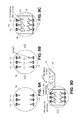
- FIG. 10A illustrates a perspective view of layers making up a sensor device according to another embodiment.
- FIG. 10B illustrates a side view of the sensor device of FIG. 10A .
- FIG. 11 is a photographic image of the sensor device according to this alternative embodiment.
- FIG. 12 illustrates the mitochondrial membrane potential measured by the second embodiment of the sensor device.
- FIGS. 13A-13F illustrate a process of making the device according to the second embodiment.
- ⁇ m drives the conversion of ADP to ATP by utilizing the proton electrochemical proton motive force ( ⁇ p), that is generated by serial reduction of electrons through the respiratory electron transport chain.
- ⁇ p proton electrochemical proton motive force
- the proton motive force generated by the oxidation steps of the electron transport chain subsequently drives the proper functioning of the mitochondria.
- Equation 2 The relationship between the proton motive force ⁇ p and the mitochondrial membrane potential ⁇ m is given by Equation 2 below.
- ⁇ p ⁇ m ⁇ [2.3( RT/F )] ⁇ pH, (2)
- ⁇ p depends on both the electrical difference across the inner membrane ( ⁇ m ) and the pH difference ( ⁇ pH) between the matrix and inner membrane space.
- ⁇ m the electrical difference across the inner membrane
- ⁇ pH the pH difference between the matrix and inner membrane space.
- the contribution of ⁇ m to the overall value of ⁇ p is much larger than that of the pH changes because of the high buffering capacity in the mitochondria.
- the device designs focuses on ⁇ m as a valid indicator of ⁇ p and, thus, the overall metabolic status of the mitochondria.
- a microfluidic TPP+ selective sensor 100 is provided.
- the TPP+ selective sensor 100 contains a plurality of test regions 102 disposed on a single substrate 104 .
- FIG. 1 is a magnified view of a single test region 102 .
- the selective sensor 100 may be multiplexed with multiple measurements made on a single platform.
- the test regions 102 may be formed atop a substrate 104 formed form silicon, glass, or quartz.
- FIG. 2 illustrates a photograph of a single test region 102 that forms the TPP+ selective sensor 100 .
- the single test region 102 has an inner chamber 106 that sits on top of the substrate 104 which, as described above, may include a silicon wafer.
- the inner chamber 106 is formed in a PDMS layer that is disposed atop the substrate 104 .
- Alternative substrates 104 include, by way of example, glass or quartz wafers.
- the inner chamber 106 defines a volume defined by a hole or void in the PDMS layer and is connected with microfluidic channels 108 .
- the microfluidic channels 108 (two of which are illustrated in FIG. 2 ) connect at one respective end to the inner chamber 106 and at an opposing end to access holes 110 .
- fluid may be injected into the microfluidic channels 108 through the access holes 110 .
- the access holes 110 may also function as ventilation holes that are connected to the microfluidic channels 108 and the inner chamber 106 .
- a silver/silver chloride electrode 112 disposed in the inner chamber 106 disposed in the inner chamber 106 .
- the silver/silver chloride electrode 112 is located on region of the substrate 104 surrounded by the inner chamber 106 .
- the silver/silver chloride electrode 112 is exposed to the contents of the inner chamber 106 .
- An ion selective permeable membrane 114 is disposed atop the inner chamber 106 .
- the inner chamber 106 is defined by a volume formed in the PDMS layer between the ion selective permeable membrane 114 and the silver/silver chloride electrode 112 disposed on the substrate 104 .
- the ion selective permeable membrane 114 allows tetraphenylphosphonium (TPP + ) ions to cross through the membrane while the same time the ion selective permeable membrane 114 seals the inner chamber 106 from a separate sensing chamber 116 .
- silver contact electrodes 118 are patterned on top of the substrate 104 and electrically connected to the silver/silver chloride electrode 112 that is contained in the inner chamber 106 .
- the silver/silver chloride electrode 112 is patterned on top of the substrate 104 .
- the microfluidic features are disposed in one or more PDMS layers that are disposed atop the substrate 104 .
- FIG. 2 illustrates three (3) such PDMS layers.
- a first PDMS layer 120 disposed atop the substrate 104 contains the microfluidic channels 108 and the inner chamber 106 .
- the second PDMS layer 122 and third PDMS layer 124 each have three holes punched out of each respective layer.
- FIG. 3 illustrates a side view of a single test region 102 of the sensor 100 .
- FIG. 3 illustrates the substrate 104 as well as the silver/silver chloride electrode 112 and the silver contact electrode 118 .
- the silver/silver chloride electrode 112 is illustrated being disposed in the inner chamber 106 .
- the ion selective membrane 114 is disposed above the inner chamber 106 and is partially sandwiched between first PDMS layer 120 and the second PDMS layer 122 .
- the ion selective membrane 114 separates the inner chamber 106 from the upper (in the context of FIG. 2 ) sensing chamber 116 . Additional volume is provided to the sensing chamber 116 by using the third PDMS layer 124 which has an aperture formed therein.
- FIG. 3 illustrates a single test region 102 it should be understood that multiple test regions 102 like that illustrated in FIG. 3 can be provided on a single substrate 104 as illustrated in FIG. 1
- the sensor 100 In one aspect of the sensor 100 , very small quantities of mitochondria are needed for determining mitochondrial membrane potential. Specifically, the device illustrated in FIGS. 1-3 may determine mitochondrial membrane potential using only nanogram-quantities of mitochondria. In one aspect, the sensor 100 measures the changes in TPP + concentration in the sensing chamber 116 as various substrates key to mitochondrial metabolism are added into the sensing chamber 116 of the microfluidic device.
- the inner chamber 106 is filled with a TPP + solution that is injected or otherwise loaded into the inner chamber 106 through the access holes 110 by using a micropipette.
- a TPP + solution that is injected or otherwise loaded into the inner chamber 106 through the access holes 110 by using a micropipette.
- other loading devices may be used such as a syringe or the like.
- the TPP + solution is left in the sensor 100 for about twelve (12) hours.
- FIG. 4 illustrates a method of measuring TPP + concentration.
- TPP + solution is injected into the inner chamber 106 , the silver contact electrode 118 of the sensor 100 is connected to a voltmeter 130 (or multimeter) that reads the TPP + concentration in the sensing chamber 116 through the measurements taken by the silver/silver chloride electrode 112 .
- a separate reference electrode 132 such as a commercial, leakage-free Ag/AgCl reference electrode (Warner Instruments), is coupled to the voltmeter 130 and is inserted into the sensing chamber 116 to measure the TPP + concentration.
- the voltmeter 130 is connected to a computer 134 via GPIB interface 136 that records the voltages read by the voltmeter 130 , the recorded time trace (or background noise) is later used to calculate the mitochondrial membrane potential with software (e.g., IGOR PRO software available from WaveMetrics (www.wavemetrics.com)).
- the computer 134 may be loaded with other software that can be used to calculate mitochondrial membrane potential as described herein.
- TPP + primes the sensor 100 for use in order to activate the TPP + ion selective membrane 114 .
- the inner filling solution is replaced (10 mM TPP + solution) after priming and no air pockets should form when the inner filling solution is replaced since air pockets would create an open circuit against the ion selective membrane 114 and signal-reading errors.
- Calibration of the sensor 100 has been conducted on the sensor 100 to ensure that measurements can be reproducible even after multiple measurements have been made.
- the sensing chamber 116 was rinsed with deionized water and respiration buffer before filling with fresh respiration buffer or 100 mM NaCl for calibrations.
- the sensor 100 was characterized using a 5-point calibration curve with TPP + concentrations ranging from 0.3 ⁇ M to 600 ⁇ M conducted in both respiration buffer and NaCl solutions.
- the potential difference between the reference electrode 132 and the silver/silver chloride electrode 112 was monitored while incrementally increasing the TPP + concentrations within the sensing chamber 116 .
- FIG. 5 illustrates two calibration curves (ISE potential vs. TPP + concentration) measured before and after a typical mitochondrial measurement and demonstrates the reproducibility, durability, and small drift of the sensor 100 between experiments.
- FIG. 6 illustrates a graph of ISE potential as a function of time. FIG. 6 shows the signal stabilizing just a few seconds following each successive addition of TPP + (arrows) and this data was subsequently used for the calibration curves.
- Heb7A is a HeLa cell-derived line which is commonly used for analytical study in research labs for their unique growth and molecular characteristics. These adherent cells were maintained in log growth phase and cultured in media consisting of MEM-e (Gibco, 11090) supplemented with 10% FCS (Hyclone, SH30072.03), 2 mM L-glutamine (Gibco, 25030), and NEAA (Gibco, 11140). The mitochondrial isolation protocol was modified from Trounce et al. See I. A. Trounce, Y. L. Kim, A. S. Jun, and D. C.
- mitochondria Upon introduction of mitochondria into the sensing chamber 116 , mitochondria quickly absorbs TPP + according to their ⁇ m leading to decrease in concentration of TPP + in the sensing chamber 116 . In addition to the uptake of TPP + by the mitochondria, the TPP + concentration in the sensing chamber 116 is also decreased by dilution when the solution of mitochondria are added into the sensing chamber 116 .
- the mitochondrial membrane potential may be calculated with the following using the following equation:
- ⁇ m RT F ⁇ ln ⁇ V 0 ⁇ [ TPP + ] 0 / [ TPP - ] t - V t - K 0 ⁇ P V m ⁇ P + K i ⁇ P ( 3 )
- Equation 3 [TPP + ] o and [TPP + ] t represent TPP + concentration in the sensing chamber 116 before the addition of mitochondria and at time t respectively.
- V o is the initial buffer volume in the sensing chamber 116 and V t represents the final volume in the chamber which includes the total mass (in mg) of mitochondrial protein (P) added in the assay.
- the mitochondrial matrix volume (V m ) was assumed to be equal to 1 ⁇ L/mg protein.
- the partition coefficients describe the innate binding and accumulation of the TPP + ion to the matrix (K i ) and external (K o ) faces of the inner membrane and are given values of 7.9 ⁇ L/mg and 14.3 ⁇ L/mg, respectively.
- the initial concentration of TPP + in the sensing chamber 116 was 7.2 ⁇ M and the initial volume of the solution is 70.5 ⁇ L.
- the initial TPP + concentration is at 6.55 ⁇ M and the initial volume is 75.5 ⁇ L.
- the TPP + concentration is 4.11 ⁇ M and the final volume of the sensing chamber is 80.5 ⁇ L.
- the mitochondrial membrane potential is 225 mV as shown in FIG. 7 .
- the mitochondrial membrane potential may be calculated either manually using Equation 3 above or, alternatively, automatically using a computer 134 loaded with software.
- the software may use a series of ISE potential measurements to calculate the concentration of TPP + .
- ISE potential measurements along with a calibration curve generated for the sensor 100 can be used to measure the concentration of TPP + .
- These values can then be input into Equation 3 along with volume measurements.
- volume changes may be input manually to the computer or they may be automatically input if, for example, the computer 134 is associated with an automatic pipetting system (or other dispensing system) capable of determining volume additions.
- FIGS. 9A-9D The microfabrication process of the sensor device of FIGS. 1-3 is schematically illustrated in FIGS. 9A-9D .
- a substrate 104 such as a silicon wafer was used as the device substrate to allow compatibility with standard semiconductor wafer-scale microfabrication technologies.
- Thin films of titanium (Ti) (50 nm) and silver (Ag) (1.5 ⁇ m) were deposited onto the silicon wafer by electron beam physical vapor deposition as shown in FIG. 9A to form contact electrodes 118 .
- the silver film was lithographically patterned on top of the Ti film into electrodes using Shipley 1827 photoresist. Wet etching was carried out using a silver etchant made of 1:1 mixture of nitric acid and DI water followed by Ti etching.
- the portion of the silver electrodes that will be situated in the inner chambers 106 were chlorinated chemically by dropping 50 ⁇ l of 0.1 M FeCl 3 solutions onto the electrode to create Ag/AgCl electrodes as seen in FIG. 9B .
- Three layers of silicone rubber (PDMS) were prepared separately by soft lithography.
- the first layer 120 has a microfluidic channel 108 with a width of 400 ⁇ m and a 50 ⁇ m depth to contain the 10 mM TPP + inner filling solution needed for the ion selective sensing.
- These microfluidic channels 108 were produced by soft lithography with a thick negative photo resist (SU-8) mold to keep the volume of the inner filling solution constant.
- FIG. 9C illustrates assembly of the first PDMS layer 120 with the microfluidic channels 108 as well as a aperture overlying the Ag/AgCl electrode 112 .
- the IS membranes 114 are first prepared and cured on a separate PDMS scaffold 140 before being positioned and deposited on the chip as illustrated in FIG. 9D .
- a clean 2 mm thick PDMS scaffold 140 was first aligned on top of the first PDMS layer 120 , so that the open 2 mm center holes of six microfluidic channels are visible from above.
- 30 ⁇ L of freshly prepared ion selective membrane solution was then carefully spotted onto this PDMS scaffold 140 to correspond to the position of the channel holes underneath.
- These TPP + ion selective (IS) membranes 114 were allowed to cure overnight at room temperature.
- the scaffold 140 with the TPP + ion selective (IS) membranes 114 was flipped over (shown by arrow in FIG. 9D ), positioned so that the cured IS membranes 114 cover the TPP + solution chamber, and the TPP + ion selective (IS) membranes 114 are gently pressed out of the scaffold 140 and onto the first PDMS layer 120 .
- Portions of the second PDMS layer 122 and third PDMS layer 124 that are to be overlaid on top of the first PDMS layer 120 and three holes in the second and third layer of PDMS are removed so that the sensing well 116 and access holes 110 are formed when these two PDMS layers 122 , 124 are aligned and assembled on top of the first PDMS layer 120 .
- the process depicted in FIGS. 9A-9D illustrates the formation of six test regions 102 as part of the sensor 100 .
- the test regions 102 are formed on a single four (4) inch Silicon wafer. It should be understood, however, that more or less test regions 102 could be formed on a single substrate 104 . Likewise, the Silicon wafer used for the substrate 104 may be smaller or larger.
- the sensor device 100 produced by the process of FIGS. 9A-9D enables scalable test sites to be integrated into a standard silicon wafer.
- the sensor device 100 advantageously requires small protein quantities—quantities that are four orders of magnitude less than current assays.
- the concentration of isolated mitochondria used in membrane potential measurements may have a concentration below 1 ng ⁇ L ⁇ 1 . In one aspect, the concentration may be around 0.3 ng ⁇ L ⁇ 1 which is four orders of magnitude smaller than concentrations used in conventional assays 3 ⁇ g ⁇ L ⁇ 1 .
- FIGS. 10A and 10B Another embodiment of a sensor device 1000 is illustrated in FIGS. 10A and 10B . Unlike the embodiment of the device shown in FIGS. 1-3 , this embodiment of the sensor device 1000 has an internal reference electrode built into the device.
- FIG. 10A is a view of each of the various layers that form the device.
- FIG. 10B is a side view of the sensor device 100 showing the various layers and components. As seen in FIGS. 10A and 10B , the sensor device 1000 sits on top of a glass substrate 1001 and silver/silver chloride electrodes 1002 are patterned on top of the glass substrate 1001 .
- a first PDMS layer 1003 is disposed atop the substrate 1001 with “L” shaped channels 1004 and 1005 cut out of the first PDMS layer 1003 .
- the “L” shaped channel 1004 forms the working electrode chamber containing inner TPP + ion solution and the working electrode 1016 detects the TPP + concentration.
- the “L” shaped channel 1005 forms the reference electrode 1015 containing an inner KCl solution.
- An ion selective membrane 1006 such as TPP membrane seals off the “L” shaped channel 1004 from the second and third PDMS layers 1008 and 1013 .
- a protective membrane 1007 seals off the “L” shaped channel 1005 from the second and third PDMS layers 1008 and 1013 .
- the protective membrane 1007 may be made of polyvinyl chloride although other materials may be used. Two large holes 1009 and 1010 are cut out of the second PDMS layer 1008 .
- the “L” channel 1004 is filled with a TPP+ solution that is injected into “L” channel 1004 through the access holes 1012 by using a syringe. Either access holes 1012 and 1014 may serve as vents.
- the TPP+ selective electrode 1016 is soaked in 10 mM TPP + Cl ⁇ solution overnight before calibration and the reference electrode 1015 was conditioned in 3 M KCl solution.
- the TPP+ selective working electrode 1016 and Ag/AgCl reference electrode 1015 were connected to the positive and negative input of a voltmeter (Agilent 34401A digital multimeter).
- the voltmeter was linked to the computer via a GPIB interface (National Instrument, GPIB-USB-HS) for data communication.
- the voltage signal from the voltmeter was acquired using Labview software, so that simultaneous monitoring of the mitochondrial membrane potential could be achieved.
- the sensor calibration was performed by adding various concentrations of TPP + Cl ⁇ solution ranging from 10 ⁇ M to 10 mM in both respiratory buffer and 0.1 M NaCl solutions at 25° C. to the sensing chamber 1011 while monitoring potential differences between working electrode and reference electrodes.
- the evaluation of the mitochondrial membrane potential was performed with human mitochondria (Heb7A) in respiration buffer (225 mM mannitol, 75 mM sucrose, 10 mM KCl, 10 mM Tris-HCl, 5 mM KH 2 PO 4 , pH 7.2). The measurements were repeated 4 times with freshly prepared mitochondria to confirm the performance and the reproducibility of the sensor. The results of the measurements showed reproducible responses under similar conditions. 25 ng of isolated mitochondria in 85 ⁇ L was used for the test resulting in a final concentration of 0.29 ng/ ⁇ L.
- the mitochondrial membrane potential ( ⁇ m) can be determined using Equation 3 as already demonstrated in this application.
- FIG. 11 illustrates an image of a complete sensor device 1000 showing the reference electrode 1015 and working electrode 1016 with arrows.
- the results of a typical assay using the sensor device 1000 are shown in FIG. 12 .
- the sensing chamber was filled with an initial volume of 71 ⁇ L respiration buffer. Once the plot baselined to zero, a 100 ⁇ M TPP + Cl ⁇ solution was added to provide a working concentration. The working concentration of TPP + was kept at about 10 ⁇ M to prevent inhibition of respiration. After stabilization, isolated mitochondria (5 ng ⁇ L/1) were added to the sensing chamber 1011 .
- the fresh mitochondria quickly took in TPP + from the chamber defined by the “L” shaped channel 1004 due to its value of ⁇ m, resulting in a lower TPP + concentration in the chamber as measured by the ion selective electrode.
- the substrate concentration became depleted, and the magnitude of ⁇ m began to decrease slowly as a result, causing a slow increase in TPP + in the sensing chamber.
- the microfluidic TPP+ selective sensor device 1000 was constructed on a microscope cover glass with PDMS layers.
- the fabrication steps are schematically illustrated in FIGS. 13A-F .
- Cover glass slides were cleaned in Piranha solution (mixture of sulfuric acid and hydrogen peroxide with the ratio of 7 to 3) overnight followed by organic solvent cleaning.
- Piranha solution mixture of sulfuric acid and hydrogen peroxide with the ratio of 7 to 3
- organic solvent cleaning a thin film of titanium (30 nm) was deposited as a seed layer and then Pd (50 nm) and Ag (2.5 ⁇ m) were deposited on the cleaned glass substrate using an electron-beam evaporator (Airco/Temescal CV-8) ( FIG. 13A ).
- Photolithography was performed with positive photoresist (Shipley 1827) for patterning silver electrodes on the glass substrate.
- Shipley 1827 was spread out by using a spin coater at 3500 rpm for 30 s with 3 ⁇ m thickness and soft-baked at 90° C. for 10 min.
- the spin-coated glass substrate was exposed to UV-light for 30 s at 6 mW cm ⁇ 2 . After a post-bake at 120° C. for 3 min, the exposed photoresist was removed in developer (MF-319, Microposit).
- Chlorination of silver was carried out electrochemically or chemically for both the reference and working electrodes ( FIG. 13B ).
- the former was performed in 0.1 M HCl solution at a constant current of 5 mA cm ⁇ 2 for 4 min, and for the latter the silver coated glass substrate was dipped into 0.1 M FeCl 3 solution for 40 s without current flow. It was found that the electrode chlorinated with the chemical method in 0.1 M FeCl 3 solution works best in terms of robustness and surface morphology. For the sensor characterization and test, only the sensor chlorinated by the chemical method was employed through the study.
- the PDMS layer was prepared by a mixture of PDMS prepolymer (Sylgard 184, Microchem) and a curing agent at a ratio of 10:1. A 7 g mixture was poured onto a 4′′ silicon wafer used as a substrate. After curing PDMS in a hot oven at 90° C. for 15 min, the cured PDMS with thickness of 1 mm was cut into the size of a cover glass and stripped out from the wafer. With a surgical blade and a flat-end needle, two “L” shaped inner filing solution reservoirs were cut in accordance with electrode sensing areas on the glass substrate.
- polyvinyl chloride (PVC) protective membrane 1007 was constructed to keep the concentration of chloride ions in the 3 M KCl inner filling solution constant.
- the PVC membrane solution prepared with 50 wt % PVC powder and 50 wt % 2-nitrophenyl-octylether was dissolved in tetrahydrofuran (THF, Fa. Fluka) and the mixture was dropped onto a cleaned glass substrate followed by curing at room temperature ( FIG. 13C ). The cured membrane was transferred onto the top of the L-shaped reservoir and glued with THF.
- the TPP + selective membrane 1006 was prepared with a mixture of 4.4 mL of THF, 0.36 mL of dioctyl phthalate, 0.15 g of PVC and 6 mg of Na+TPB ⁇ (tetraphenylboron), and poured onto a glass substrate. The mixture was evaporated slowly at room temperature for a few hours. The membrane 1006 was carefully glued to the top of the TPP + reservoir with THF. The second PDMS layer having two openings and four access holes was placed on top of the membranes to secure the bonding of membranes between PDMS layers by pressing down the membranes ( FIG. 13D ).
- microfluidic sensor device has largely been described in the context of using an ion selective membrane together with an electrode, there are alternative embodiments of using other sensing modalities to analyze mitochondrial bioenergetics and more specifically measure the mitochondrial membrane potential ⁇ m of the sample.
- the sample may contain mitochondria present in intact cells or, alternatively, the sample may contain isolated or enriched mitochondria.
- one or more fluorescent dyes are loaded with a sample into a microfluidic device having one or more chambers therein having a volume within 0 ⁇ l to about 100 ⁇ l.
- fluorescent compounds are cationic as well as lipophilic and therefore can be used to quantitatively measure the mitochondrial inner membrane potential ( ⁇ ⁇ m ).
- Some of the most commonly used fluorescent dyes are rhodamine 123 (Rh123), 5,5′6,6′-tetrachloro-1,1′,3,3′-tetraethylbenzamidazolocarbocyanine (JC1), tetramethylrhodamine ethyl ester (TMRE), tetramethylrhodamine methyl ester (TMRM), DiOC6 and DASPMI. These dyes can diffuse across the cell membrane easily and distribute between cellular compartments in response to the standing electrochemical gradients. For intact cells, measurements ⁇ ⁇ m with fluorescent dyes can be performed by comparing the fluorescence intensity from different compartments of the cells using a CCD camera, confocal microscope, or the like.
- the working principle is that when the dyes are used at low concentration, the fluorescence signal shows a linear relationship with the dye concentration and the dye distribution between cell compartments follows a Nernstian relationship.
- Using fluorescent compounds for the measurements of ⁇ ⁇ m in isolated mitochondria may be accomplished by measuring the wavelength shift in fluorescence.
- JC-1 which is a dual color dye
- a standard curve between fluorescence signal and ⁇ ⁇ m can be constructed by using different bath potassium ion concentrations [K] out in the presence of valinomycin.
- TMRM, TMRE, Rh123 which are monochromic fluorescent dye
- a ratiometric approach can be used to quantify ⁇ ⁇ m . More specifically, because these three dyes show a red shift in their excitation/emission fluorescence spectra when they are uptaken by the mitochondria, the amount of the wavelength shift can be used to determine the dye distribution across the mitochondrial membrane and therefore can be used to calculate ⁇ ⁇ m . See R. C. Scaduto, Jr., L. W. Grotyohahn, “Measurement of Mitochondrial Membrane Potential Using Fluorescent Rhodamine Derivatives”, Biophysical Journal, 76, 469-477, (1999), which is incorporated by reference herein. DiOC6 and DASPMI are other dyes commonly used in flow cytometry for ⁇ ⁇ m determination and may also be used.
- At least one radioactive compound is added to the sample and the mitochondrial membrane potential ⁇ m of the sample is measured based at least in part on radioactivity measurements.
- a similar sized sample chamber volume is used in this alternative embodiment.
- the method of using radioactive compounds to determine ⁇ ⁇ m generally involves evaluating the distribution of 86 Rb + or [ 3 H]TPP + across the inner membrane in the presence of valinomycin. Theses cations distributes across the inner mitochondrial membrane in accordance with ⁇ ⁇ m , following a Nernstian relationship.
- a radiation counter device e.g., scintillation counter
- the mitochondrial membrane potential ⁇ m may be measured directly using capacitive sensing based on nanomaterials such as carbon nanotubes and graphene.
- nanomaterials such as carbon nanotubes and graphene.
- analogs of a silicon transistor can be built within a sample chamber using conventional metals such as gold, silver, or platinum as the source and drain while the nanomaterials serve as gate.
- the carbon nanotubes and graphene are thus conductors contained within the sample chamber.
- the sample chamber may have similar small volumes (e.g., between 0 ⁇ l to about 100 ⁇ l).
- the conductance of the conductors will change in the presence of individual mitochondria placed on top of the same in a microfluidic environment. This change correlates with ⁇ ⁇ m .
Landscapes
- Health & Medical Sciences (AREA)
- Life Sciences & Earth Sciences (AREA)
- Chemical & Material Sciences (AREA)
- Physics & Mathematics (AREA)
- Engineering & Computer Science (AREA)
- Biomedical Technology (AREA)
- Analytical Chemistry (AREA)
- Biochemistry (AREA)
- Molecular Biology (AREA)
- Pathology (AREA)
- Immunology (AREA)
- General Physics & Mathematics (AREA)
- General Health & Medical Sciences (AREA)
- Food Science & Technology (AREA)
- Optics & Photonics (AREA)
- Medicinal Chemistry (AREA)
- Hematology (AREA)
- Biophysics (AREA)
- Urology & Nephrology (AREA)
- Chemical Kinetics & Catalysis (AREA)
- Electrochemistry (AREA)
- Investigating Or Analyzing Materials By The Use Of Electric Means (AREA)
- Apparatus Associated With Microorganisms And Enzymes (AREA)
Abstract
Description
Δp=ΔΨ m−[2.3(RT/F)]ΔpH, (2)
Claims (29)
Priority Applications (1)
| Application Number | Priority Date | Filing Date | Title |
|---|---|---|---|
| US13/412,515 US8961759B2 (en) | 2011-03-10 | 2012-03-05 | Device and method for mitochondrial membrane potential assessment |
Applications Claiming Priority (2)
| Application Number | Priority Date | Filing Date | Title |
|---|---|---|---|
| US201161451370P | 2011-03-10 | 2011-03-10 | |
| US13/412,515 US8961759B2 (en) | 2011-03-10 | 2012-03-05 | Device and method for mitochondrial membrane potential assessment |
Publications (2)
| Publication Number | Publication Date |
|---|---|
| US20120247980A1 US20120247980A1 (en) | 2012-10-04 |
| US8961759B2 true US8961759B2 (en) | 2015-02-24 |
Family
ID=46925817
Family Applications (1)
| Application Number | Title | Priority Date | Filing Date |
|---|---|---|---|
| US13/412,515 Active 2033-01-16 US8961759B2 (en) | 2011-03-10 | 2012-03-05 | Device and method for mitochondrial membrane potential assessment |
Country Status (1)
| Country | Link |
|---|---|
| US (1) | US8961759B2 (en) |
Families Citing this family (7)
| Publication number | Priority date | Publication date | Assignee | Title |
|---|---|---|---|---|
| US8895312B2 (en) * | 2012-08-20 | 2014-11-25 | The Regents Of The University Of California | Nanofluidic platform for single mitochondria analysis |
| JP6353451B2 (en) * | 2013-08-23 | 2018-07-04 | 株式会社朝日Fr研究所 | Micro chemical chip and reaction device |
| US10188989B2 (en) | 2013-09-27 | 2019-01-29 | Ohio State Innovation Foundation | Electroosmotic devices for fluid handling |
| US10983088B2 (en) * | 2016-03-28 | 2021-04-20 | University Of Massachusetts | Coulometric microfluidic sensors using a silver band electrode, and methods thereof |
| EP3721217A4 (en) * | 2017-12-08 | 2021-12-29 | Enuvio Inc. | Microfluidic chip and method for making the same |
| CN114839241B (en) * | 2022-02-28 | 2024-07-16 | 京东方科技集团股份有限公司 | Detection substrate and detection method and detection device thereof |
| CN115420779B (en) * | 2022-09-14 | 2025-06-03 | 西南大学 | Pt NPs@TPB NCs/dissolved O2 ternary electrochemiluminescent biosensor, preparation method and application |
-
2012
- 2012-03-05 US US13/412,515 patent/US8961759B2/en active Active
Non-Patent Citations (14)
| Title |
|---|
| A. Baez-Ruiz, et al. "Metabolic adaptations of liver mitochondria during restricted feeding schedules", AJP- Gastrointestinal Liver Physiology, vol. 289, 2005, p. G1015-1023. * |
| A. Baracca, et al. "Rhodamine 123 as a probe of mitochondrial membrane potential: evaluation of proton flux through Fo during ATP synthesis", Biochimica Et Biophysica ACTA, vol. 1606, 2003, p. 137-146. * |
| Duchen, M. R., Mitochondria in health and disease: perspectives on a new mitochondrial biology, Molecular Aspects of Medicine, 25, 365-451, (2004). |
| Kamo, N. et al. Membrane Potential of Mitochondrial Measured with an Electrode Sensitive to Tetraphenyl Phosphonium and Relationship between Proton Electrochemical Potential and Phosphorylation Potential in Steady State, J. Membr. Biol. 1979, 49, 105-121. |
| Labajova, A. et al., Evaluation of mitochondrial membrane potential using a computerized device with a tetraphenylphosphonium-selective electrode, Anal. Biochem., 2006, 353, 37-42. |
| Nicholls, D.G.,The influence of respiration and ATP hydrolysis on the proton electrochemical gradient across the inner membrane of rat liver mitochondria as determined by ion distribution, European Journal of Biochemistry 50, 305-315, (1974). |
| Perry, S. W. et al., Mitochondrial membrane potential probes and the proton gradient: a practical usage guide, Biotechniques,50(2),98-115, (2011). |
| R. C. Scaduto, Jr. and L. W. Grotyohann, "Measurement of mitochondrial membrane potential using fluorescent rhodamine derivatives", Biophysical Journal, vol. 76, Jan. 1999, p. 469-477. * |
| Reers, M. et al., Mitochondrial membrane potential monitored by JC-1 Dye, Methods in Enzymology, 260, 406-417, (1995). |
| Satake, Hiromu et al., A Coated Wire Electrode Sensitive to Tetraphenylphosphonium Ion for Measurement of the Mitochondrial Membrane Potential, Analytical Letters, 24(2), 295-304 (1991). |
| Scaduto, R. C. et al., Measurement of Mitochondrial Membrane Potential Using Fluorescent Rhodamine Derivatives, Biophysical Journal, 76, 469-477, (1999). |
| T.-S. Lim, et al. "Assessment of mitochondrial membrane potential using an on-chip microelectrode in a microfluidic device", Lab on a Chip, vol. 10, No. 13, Jul. 2010, p. 1683-1688. * |
| Trounce, I. A. et al., Assessment of mitochondrial oxidative phosphorylation in patient muscle biopsies, lymphoblasts, and transmitochondrial cell lines, Methods Enzymol, vol. 264, pp. 484-509, 1996. |
| Zillberstein, D. et al., Proton electrochemical gradient in Escherichia coli cells and its relation to active transport of lactose, 18(4), 669-673, (1979). |
Also Published As
| Publication number | Publication date |
|---|---|
| US20120247980A1 (en) | 2012-10-04 |
Similar Documents
| Publication | Publication Date | Title |
|---|---|---|
| US8961759B2 (en) | Device and method for mitochondrial membrane potential assessment | |
| Shajari et al. | MicroSweat: A wearable microfluidic patch for noninvasive and reliable sweat collection enables human stress monitoring | |
| Lee et al. | Single microfluidic electrochemical sensor system for simultaneous multi-pulmonary hypertension biomarker analyses | |
| CN1558235B (en) | Method and detection element for determining the presence and/or amount of an analyte in a blood sample | |
| Truman et al. | Monitoring liquid transport and chemical composition in lab on a chip systems using ion sensitive FET devices | |
| US20130056367A1 (en) | Integrated sensing device and related methods | |
| US20160033438A1 (en) | Paper-Based Reference Electrode And Potentiometric Ion Sensing | |
| JPH03503677A (en) | reference electrode | |
| US20140231274A1 (en) | Single molecule detection method and single molecule detection apparatus for biological molecule, and disease marker testing apparatus | |
| JP5608260B2 (en) | Biosensor system and method for measuring concentration of analyte | |
| Kannan et al. | Highly sensitive electrochemical determination of neutrophil gelatinase-associated lipocalin for acute kidney injury | |
| Uhlig et al. | Miniaturized ion-selective chip electrode for sensor application | |
| Wiedemair et al. | Developing an amperometric hydrogen peroxide sensor for an exhaled breath analysis system | |
| Lim et al. | Assessment of mitochondrial membrane potential using an on-chip microelectrode in a microfluidic device | |
| US10254262B2 (en) | Hydrogen sulfide detecting apparatus | |
| Nakamura et al. | Development of pipette tip-based enzyme-linked immunosorbent assay using a microfiber-type structure-incorporated pipette tip for rapid on-site diagnosis | |
| Ges et al. | On-chip acidification rate measurements from single cardiac cells confined in sub-nanoliter volumes | |
| Lim et al. | Wafer-scale mitochondrial membrane potential assays | |
| Tonooka et al. | Lipid bilayer on a microdroplet integrated with a patterned Ag/AgCl microelectrode for voltage-clamp fluorometry of membrane transport | |
| WO2022162126A1 (en) | Electrochemical measurement with additional reference measurement | |
| Nomaru et al. | Needle-Type Oxygen Microsensor Made by Hybrid 3D Microfabrication | |
| KR102447193B1 (en) | Multi-gap electrochemical sensor and quantitative analysis method using same | |
| Zand | Biosensors for Mitochondrial Membrane Potential Analysis | |
| Lim et al. | On-Chip Ion-selective Microesensor for Evaluation of Mitochondrial Membrane Potential | |
| JP2004053401A (en) | pH ELECTRODE |
Legal Events
| Date | Code | Title | Description |
|---|---|---|---|
| AS | Assignment |
Owner name: THE REGENTS OF THE UNIVERSITY OF CALIFORNIA, CALIF Free format text: ASSIGNMENT OF ASSIGNORS INTEREST;ASSIGNORS:BURKE, PETER;LIM, TAE-SUN;DAVILA, ANTONIO;AND OTHERS;SIGNING DATES FROM 20120306 TO 20120505;REEL/FRAME:033683/0416 |
|
| STCF | Information on status: patent grant |
Free format text: PATENTED CASE |
|
| AS | Assignment |
Owner name: NATIONAL INSTITUTES OF HEALTH (NIH), U.S. DEPT. OF Free format text: CONFIRMATORY LICENSE;ASSIGNOR:UNIVERSITY OF CALIFORNIA SYS OFFICE/PRES;REEL/FRAME:038926/0208 Effective date: 20140521 |
|
| MAFP | Maintenance fee payment |
Free format text: PAYMENT OF MAINTENANCE FEE, 4TH YR, SMALL ENTITY (ORIGINAL EVENT CODE: M2551); ENTITY STATUS OF PATENT OWNER: SMALL ENTITY Year of fee payment: 4 |
|
| MAFP | Maintenance fee payment |
Free format text: PAYMENT OF MAINTENANCE FEE, 8TH YR, SMALL ENTITY (ORIGINAL EVENT CODE: M2552); ENTITY STATUS OF PATENT OWNER: SMALL ENTITY Year of fee payment: 8 |