US8953543B2 - Communication terminal, control device, communication method, control method, program, and integrated circuit - Google Patents
Communication terminal, control device, communication method, control method, program, and integrated circuit Download PDFInfo
- Publication number
- US8953543B2 US8953543B2 US13/642,581 US201113642581A US8953543B2 US 8953543 B2 US8953543 B2 US 8953543B2 US 201113642581 A US201113642581 A US 201113642581A US 8953543 B2 US8953543 B2 US 8953543B2
- Authority
- US
- United States
- Prior art keywords
- communication
- terminal
- frequency channels
- control device
- terminals
- Prior art date
- Legal status (The legal status is an assumption and is not a legal conclusion. Google has not performed a legal analysis and makes no representation as to the accuracy of the status listed.)
- Expired - Fee Related, expires
Links
Images


Classifications
-
- H—ELECTRICITY
- H04—ELECTRIC COMMUNICATION TECHNIQUE
- H04W—WIRELESS COMMUNICATION NETWORKS
- H04W74/00—Wireless channel access
- H04W74/08—Non-scheduled access, e.g. ALOHA
- H04W74/0808—Non-scheduled access, e.g. ALOHA using carrier sensing, e.g. carrier sense multiple access [CSMA]
-
- H—ELECTRICITY
- H04—ELECTRIC COMMUNICATION TECHNIQUE
- H04W—WIRELESS COMMUNICATION NETWORKS
- H04W72/00—Local resource management
- H04W72/02—Selection of wireless resources by user or terminal
Definitions
- the present invention relates to methods of avoiding packet collision caused by hidden terminal problems in wireless communication systems.
- CSMA/CA Carrier Sence Multiple Access with Collision Avoidance
- CSMA/CA there is a situation where two terminals in a communication area provided by a control device (referred to also as a “control point”) cannot receive radio signals from each other due to the distance between the terminals, influence of an obstacle such as a wall, or the like.
- a control point Such a problem caused by signal exchange failure is called a “hidden terminal problem”.
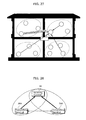
- FIG. 28 is a conceptual diagram for explaining the “hidden terminal problem”.
- each of a transmitting terminal 30 A and a transmitting terminal 30 B communicates with a receiving terminal 40 .
- the transmitting terminals 30 A and 30 B fail to detect signals transmitted from each other by their carrier sences, and therefore transmit signals to the receiving terminal 40 at the same time, thereby causing collision between the signals.
- Non-Patent Literature 1 As shown in FIG. 29 , the transmitting terminals 30 A and 30 B and the receiving terminal 40 exchange a control signal called a Request to Send/Clear to Send (RTS/CTS). It is thereby possible to reduce a possibility of collision between data signals transmitted from the transmitting terminals 30 A and 30 B.
- RTS/CTS Request to Send/Clear to Send
- the transmitting terminal 30 A Prior to data transmission, the transmitting terminal 30 A transmits a RTS signal to the receiving terminal 40 .
- the receiving terminal 40 transmits a CTS signal to the transmitting terminals 30 A and 30 B.
- the transmitting terminal 30 B receives the CTS signal and waits for transmission, stopping signal transmission.
- the transmitting terminal 30 A receiving the CTS signal starts its data transmission.
- the RTS/CTS signal exchange between the transmitting terminal 30 A and the receiving terminal 40 causes the transmitting terminal 30 B to wait for transmission. It is therefore possible to reduce a probability of collision between signals transmitted from the transmitting terminals 30 A and 30 B.
- Patent Literature 1 Another technique for preventing the hidden terminal problem without using RTS/CTS is disclosed in Patent Literature 1.
- the terminal selects a control device having a low probability of hidden terminal problem to be connected.
- the terminal scans a frequency channel of a control device 1 to measure traffic statistic on a network, thereby obtaining a channel occupancy. Next, the terminal performs the same scanning for a frequency channel of a control device 2 .
- each of the control devices 1 and 2 scans a using frequency channel to obtain traffic statistics on the network. Then, based on the traffic statistics, a channel use rate of the terminal is calculated to be provided to the terminal.
- the terminal thereby selects a control device to be connected, according to the channel occupancy and the channel use rates which are obtained in the above-described manner.
- Patent Literature 1 under the observation that signals transmitted from all of terminals in a communication area arrive at a control device, a target terminal is connected to a control device determined as having least hidden terminal problem in consideration of a difference between a traffic amount scanned by each of the control devices and a traffic amount scanned by the terminal.
- Non-Patent Literature 1 RTS/CTS signals become overhead of data communication. As a result, a throughput is decreased. In particular, if a data size is small, influence of the overhead is considerable.
- Non-Patent Literature 1 in the random access control system, some terminal would not communicate while a certain terminal is scanning a frequency channel.
- an object of the present invention is to provide a communication terminal, a control device, a communication method, and a control method each of which is capable of reducing influence caused in detecting hidden terminals even if the number of frequency channels is increased.
- a communication terminal comprising: a communication unit configured to exchange signals via a frequency channel selected from a plurality of frequency channels; a first detection unit configured to detect, for each of the frequency channels, a number of one or more other communication terminals performing wireless communication via the each of the frequency channels, by causing the communication unit to receive a notification signal indicating the number from a control device while the frequency channels are sequentially switched; a second detection unit configured to count, for the each of the frequency channels, a number of one or more other communication terminals performing wireless communication via the each of the frequency channels, by causing the communication unit to receive acknowledgement signals transmitted from the one or more other communication terminals while the frequency channels are sequentially switched; and a channel control unit configured to (i) select, from the frequency channels, a frequency channel having a least difference between the number detected by the first detection unit and the number counted by the second detection unit, and (ii) cause the communication unit to exchange the signals with the control device via the selected frequency
- the present invention can be implemented not only as the above-described device, but also as: an integrated circuit including the processing units included in the device; a control method including steps performed by the processing units included in the device: or a program causing a computer to execute these steps.
- a terminal to be newly connected to a control device can reduce a probability of hidden terminal problem.
- the influence caused in detecting hidden terminals can be reduced.
- FIG. 1 is a configuration example of a wireless communication system according to Embodiment 1 of the present invention.
- FIG. 2 is a functional block diagram of communication terminal according to Embodiment 1 of the present invention.
- FIG. 3 is a functional block diagram of a control device according to Embodiment 1 of the present invention.
- FIG. 4A is a flowchart of processing performed by a newly-connecting terminal according to Embodiment 1 of the present invention.
- FIG. 4B is a flowchart of processing performed by a control device according to Embodiment 1 of the present invention.
- FIG. 4C is a flowchart of processing performed by an already-connected terminal according to Embodiment 1 of the present invention.
- FIG. 5 is a configuration example of a wireless communication system according to Embodiment 2 of the present invention.
- FIG. 6 is a functional block diagram of a communication terminal according to Embodiment 2 of the present invention.
- FIG. 7A is a flowchart of processing performed by a newly-connecting terminal according to Embodiment 2 of the present invention.
- FIG. 7B is a flowchart of processing performed by a control device according to Embodiment 2 of the present invention.
- FIG. 7C is a flowchart of processing performed by an already-connected terminal according to Embodiment 2 of the present invention.
- FIG. 8 is a diagram showing an example of a connection sequence according to Embodiment 2 of the present invention.
- FIG. 9 is a diagram showing a traffic amount of a hidden terminal for each frequency channel according to Embodiment 2 of the present invention.
- FIG. 10 is a configuration example of a wireless communication system according to Embodiment 3 of the present invention.
- FIG. 11 is a functional block diagram of a communication terminal according to Embodiment 3 of the present invention.
- FIG. 12 is a functional block diagram of a control device according to Embodiment 3 of the present invention.
- FIG. 13A is a flowchart of processing performed by a newly-connecting terminal according to Embodiment 3 of the present invention.
- FIG. 13B is a flowchart of processing performed by a control device according to Embodiment 3 of the present invention.
- FIG. 13C is a flowchart of processing performed by an already-connected terminal according to Embodiment 3 of the present invention.
- FIG. 14 is a diagram showing an example of a connection sequence according to Embodiment 3 of the present invention.
- FIG. 15 is a configuration example of a wireless communication system according to Embodiment 4 of the present invention.
- FIG. 16 is a functional block diagram of a communication terminal according to Embodiment 4 of the present invention.
- FIG. 17 is a functional block diagram of a control device according to Embodiment 4 of the present invention.
- FIG. 18A is a flowchart of processing performed by a newly-connecting terminal according to Embodiment 4 of the present invention.
- FIG. 18B is a flowchart of processing performed by a control device according to Embodiment 4 of the present invention.
- FIG. 18C is a flowchart of processing performed by an already-connected terminal according to Embodiment 4 of the present invention.
- FIG. 19 is a diagram showing an example of a connection sequence according to Embodiment 4 of the present invention.
- FIG. 20 is a configuration example of a wireless communication system according to Embodiment 5 of the present invention.
- FIG. 21 is a functional block diagram of a communication terminal according to Embodiment 5 of the present invention.
- FIG. 22 is a functional block diagram of a control device according to Embodiment 5 of the present invention.
- FIG. 23A is a flowchart of processing performed by a newly-connecting terminal according to Embodiment 5 of the present invention.
- FIG. 23B is a flowchart of processing performed by a control device according to Embodiment 5 of the present invention.
- FIG. 23C is a flowchart of processing performed by an already-connected terminal according to Embodiment 5 of the present invention.
- FIG. 24 is a diagram showing an example of a connection sequence according to Embodiment 5 of the present invention.
- FIG. 25 is a diagram showing an example of the case where power of transmitting an acknowledgement packet is controlled, according to Embodiment 5 of the present invention.
- FIG. 26 is a configuration example of a wireless communication system having a high possibility of hidden terminal problem, according to Embodiment 5 of the present invention.
- FIG. 27 is an example of a wireless communication system in the case where each room in home has a terminal, according to Embodiment 5 of the present invention.
- FIG. 28 is an example of a system configuration with hidden terminal problem.
- FIG. 29 is an example of hidden terminal problem in the case of using RTS/CTS disclosed in Non-Patent Literature 1.
- FIG. 30 is an example of selecting a control device in addressing hidden terminal problem disclosed in Non-Patent Literature 1.
- a communication terminal comprising: a communication unit configured to exchange signals via a frequency channel selected from a plurality of frequency channels; a first detection unit configured to detect, for each of the frequency channels, a number of one or more other communication terminals performing wireless communication via the each of the frequency channels, by causing the communication unit to receive a notification signal indicating the number from a control device while the frequency channels are sequentially switched; a second detection unit configured to count, for the each of the frequency channels, a number of one or more other communication terminals performing wireless communication via the each of the frequency channels, by causing the communication unit to receive acknowledgement signals transmitted from the one or more other communication terminals while the frequency channels are sequentially switched; and a channel control unit configured to (i) select, from the frequency channels, a frequency channel having a least difference between the number detected by the first detection unit and the number counted by the second detection unit, and (ii) cause the communication unit to exchange the signals with the control device via the selected frequency channel.
- the notification signal and the acknowledgement signals it is possible to detect, for each of the frequency channels, the number of communication terminals existing in a range where wireless signals (radio waves) arrive at the terminals. As a result, it is possible to perform wireless communication by selecting a frequency channel having a least number of hidden terminals.
- the “acknowledgement signals” received by the above-described communication terminal may propagate from the other communication terminals directly to the communication terminal without being relayed by the control device or the like.
- the channel control unit is configured to (i) select, from the frequency channels, a frequency channel having the number detected by the first detection unit which is equal to the number counted by the second detection unit, and (ii) causes the communication unit to exchange the signals with the control device via the selected frequency channel.
- the channel control unit is configured, after the first detection unit detects the number for each of the frequency channels, to cause the communication unit to transmit an order signal to the control device, the order signal being for ordering the control device to transmit a request signal for requesting the one or more other communication terminals to transmit the acknowledgement signals.
- the communication terminal further includes a third detection unit configured to detect, for each of the frequency channels, a number of the one or more other communication terminals which are one or more source terminals transmitting signals, by causing the communication unit to receive the signals while the first detection unit detects the number for each of the frequency channels, wherein the channel control unit is configured to cause the communication unit to transmit the order signal to the control device, the order signal being for ordering the control device to transmit the request signal via the respective frequency channels in order of decreasing a difference between the number included in the notification signal and the number of the one or more source terminals.
- a third detection unit configured to detect, for each of the frequency channels, a number of the one or more other communication terminals which are one or more source terminals transmitting signals, by causing the communication unit to receive the signals while the first detection unit detects the number for each of the frequency channels, wherein the channel control unit is configured to cause the communication unit to transmit the order signal to the control device, the order signal being for ordering the control device to transmit the request signal via the respective frequency channels in order of decreasing
- the communication terminal further includes a third detection unit configured to detect, for the each of the frequency channels, information for identifying the one or more other communication terminals which are one or more source terminals transmitting signals, by causing the communication unit to receive the signals while the first detection unit detects the number for each of the frequency channels, wherein the channel control unit is configured to cause the communication unit to transmit the order signal to the control device, the order signal being for ordering the control device to transmit the request signal to only a communication terminal not detected by the third detection unit.
- a third detection unit configured to detect, for the each of the frequency channels, information for identifying the one or more other communication terminals which are one or more source terminals transmitting signals, by causing the communication unit to receive the signals while the first detection unit detects the number for each of the frequency channels, wherein the channel control unit is configured to cause the communication unit to transmit the order signal to the control device, the order signal being for ordering the control device to transmit the request signal to only a communication terminal not detected by the third detection unit.
- the communication terminal further includes a signal generation unit configured, while the frequency channels are sequentially switched, to (i) generate a request signal for requesting the one or more other communication terminals to transmit the acknowledgement signals, and (ii) cause the communication unit to transmit the request signal.
- a signal generation unit configured, while the frequency channels are sequentially switched, to (i) generate a request signal for requesting the one or more other communication terminals to transmit the acknowledgement signals, and (ii) cause the communication unit to transmit the request signal.
- the “request signal” received by the above-described other communication terminals may propagate from the communication terminal (source terminal) transmitting the signal directly to the other communication terminals without being relayed by the control device or the like.
- a control device that wirelessly communicates with a communication terminal, the control device comprising: a communication unit configured to exchange signals via a frequency channel selected from a plurality of frequency channels; a management unit configured to hold, for each of the frequency channels, information of one or more communication terminals performing wireless communication via the each of the frequency channels; a first signal generation unit configured, while the frequency channels are sequentially switched, to (i) generate a notification signal including a number of the one or more communication terminals performing wireless communication via the each of the frequency channels, and (ii) cause the communication unit to transmit the notification signal to a new communication terminal to newly start communication; and a second signal generation unit configured, while the frequency channels are sequentially switched, to (i) generate a request signal for requesting the one or more communication terminals to transmit acknowledgement signals to the new communication terminal, and (ii) cause the communication unit to transmit the request signal to the one or more communication terminals.
- the new communication terminal can select a frequency channel with a least number of hidden terminals.
- control device further includes a channel control unit configured to cause the second signal generation unit to generate the request signal for each of the frequency channels based on an order signal, the order signal being for ordering the new communication terminal to transmit the request signal to the one or more communication terminals.
- the channel control unit is configured to (i) cause the communication unit to receive, for each of the frequency channels, the order signal including the number of the one or more communication terminals found by the new communication terminal, and (ii) cause the second signal generation unit to generate the request signal sequentially for the frequency channels in order of decreasing a difference between the number held in the management units and the number included in the order signal.
- the channel control unit is configured to (i) cause the communication unit to receive the order signal including information for identifying the one or more communication terminals found by the new communication terminal, and (ii) cause the second signal generation unit to generate the request signal to be transmitted to only a communication terminal not found by the new communication terminal.
- control device gathers, for each predetermined time period, statistics on a traffic amount of each of the one or more communication terminals managed by the management unit, and (ii) causes the control unit to select, from the frequency channels, a frequency channel having a least traffic amount of a communication terminal from which the new communication terminal fails to receive an acknowledgement signal.
- a communication method of wirelessly communicating via a plurality of frequency channels comprising: detecting, for each of the frequency channels, a number of one or more other communication terminals performing wireless communication via the each of the frequency channels, by receiving a notification signal indicating the number from a control device while the frequency channels are sequentially switched; counting, for the each of the frequency channels, a number of one or more other communication terminals performing wireless communication via the each of the frequency channels, by receiving acknowledgement signals transmitted from the one or more other communication terminals while the frequency channels are sequentially switched; and (i) selecting, from the frequency channels, a frequency channel having a least difference between the number detected in the detecting and the number counted in the counting, and (ii) exchanging the signals with the control device via the selected frequency channel.
- a control method of controlling a control device that wirelessly communicates with a communication terminal comprising: holding, for each of a plurality of the frequency channels, information of one or more communication terminals performing wireless communication via the each of the frequency channels; transmitting, to a new communication terminal to newly start communication, a notification signal including a number of the one or more communication terminals performing wireless communication via the each of the frequency channels, while the frequency channels are sequentially switched; and transmitting, the one or more communication terminals, a request signal for requesting the one or more communication terminals to transmit acknowledgement signals to the new communication terminal, while the frequency channels are sequentially switched.
- a program causing a computer to perform wireless communication, the program causing the computer to execute: detecting, for each of the frequency channels, a number of one or more other communication terminals performing wireless communication via the each of the frequency channels, by receiving a notification signal indicating the number from a control device while the frequency channels are sequentially switched; counting, for the each of the frequency channels, a number of one or more other communication terminals performing wireless communication via the each of the frequency channels, by receiving acknowledgement signals transmitted from the one or more other communication terminals while the frequency channels are sequentially switched; and (i) selecting, from the frequency channels, a frequency channel having a least difference between the number detected in the detecting and the number counted in the counting, and (ii) exchanging the signals with the control device via the selected frequency channel.
- an integrated circuit used in a communication terminal performing wireless communication comprising: a communication unit configured to exchange signals via a frequency channel selected from a plurality of frequency channels; a first detection unit configured to detect, for each of the frequency channels, a number of one or more other communication terminals performing wireless communication via the each of the frequency channels, by causing the communication unit to receive a notification signal indicating the number from a control device while the frequency channels are sequentially switched; a second detection unit configured to count, for the each of the frequency channels, a number of one or more other communication terminals performing wireless communication via the each of the frequency channels, by causing the communication unit to receive acknowledgement signals transmitted from the one or more other communication terminals while the frequency channels are sequentially switched; and a channel control unit configured to (i) select, from the frequency channels, a frequency channel having a least difference between the number detected by the first detection unit and the number counted by the second detection unit, and (ii) cause the communication unit
- FIG. 1 is a configuration example of a wireless communication system according to Embodiment 1.
- the wireless communication system in FIG. 1 includes: a control device 200 that controls a wireless network; and terminals 100 A to 100 F that wirelessly communicate with the control device 200 under the control of the control device 200 .
- control device 200 regularly transmits a beacon signal including information for controlling the wireless network.
- Ch 1 a frequency channel 1
- Ch 2 a frequency channel 2
- the terminals 100 B to 100 F are already connected to the control device 200 for the wireless communication. They are referred to already-connected terminals (or “connected terminals”).
- the terminals 100 B and 100 C uses Ch 2 for the wireless communication with the control device 200 .
- the terminals 100 D, 100 E, and 100 F use Ch 1 for the wireless communication with the control device 200 .
- the terminal 100 A is a terminal to be newly connected to the control device 200 (hereinafter, referred to also as a “newly-connecting terminal).
- FIG. 2 is a functional block diagram of a representative communication terminal 100 according to Embodiment 1.
- the communication terminal 100 includes a receiving unit 101 , a data processing unit (second detection unit) 102 , an acknowledgment packet generation unit 103 , a selected-channel notification generation unit 104 , a transmission unit 105 , a beacon processing unit (first detection unit) 106 , and a channel control unit 110 .
- the receiving unit 101 receives radio signal from an external device (the control device 200 or another communication terminal, the same applies hereinafter). Then, the receiving unit 101 demodulates the received radio signal, and then converts the demodulated signal from analog signal to digital signal (hereinafter, the processing is referred to as A/D conversion).
- the receiving unit 101 receives a request signal (acknowledgement packet transmission request) and a beacon signal (terminal number notification signal) from the control device 200 .
- the receiving unit 101 receives acknowledgement signals (acknowledgement packets) from terminals which have already been connected to the control device 200 .
- the transmission unit 105 converts transmission signal generated by the acknowledgment packet generation unit 103 , the selected-channel notification generation unit 104 , or the like from digital signal to analog signal (hereinafter, the processing is referred to as D/A conversion). Then, the transmission unit 105 modulates the converted signal, and transmits the modulated signal.
- a set of the receiving unit 101 and the transmission unit 105 forms a communication unit.
- This communication unit exchanges signal with the external device via selected one of the frequency channels.
- the frequency channel to be used for communication is determined by the channel control unit 110 and then notified to the control device 200 .
- the data processing unit 102 detects, for each of the frequency channels, the number of the other communication terminals which is found by the acknowledgement signals (acknowledgement packets) received by the receiving unit 101 . Furthermore, the data processing unit 102 notifies the acknowledgment packet generation unit 103 of that the receiving unit 101 receives a request signal (acknowledgement packet transmission request).
- the beacon processing unit 106 detects, for each of the frequency channels, the number of the other communication terminals (connected-terminal number) performing wireless communication via the frequency channel, based on the beacon signal (terminal number notification signal) received by the receiving unit 101 .
- the channel control unit 110 compares, for each of the frequency channels, the connected-terminal number obtained from the beacon signal to the connected-terminal number detected using the acknowledgement packets. Therefore, the channel control unit 110 determines whether or not any hidden terminal exists, and thereby selects a frequency channel to be used for communication.
- the selected-channel notification generation unit 104 generates a packet for notifying the selected frequency channel to the control device 200 (connection request, selected-channel notification, or the like), and causes the transmission unit 105 to transmit the generated packet.
- the acknowledgment packet generation unit 103 According to a request for transmitting an acknowledgement packet (hereinafter, referred to also as an “acknowledgement packet transmission request) which is notified from the data processing unit 102 , the acknowledgment packet generation unit 103 generates an acknowledgement packet and causes the transmission unit 105 to transmit the acknowledgement packet.
- FIG. 3 is a functional block diagram of the control device 200 according to Embodiment 1.
- the control device 200 includes a receiving unit 201 , a data processing unit 202 , a management unit 203 , a transmission request generation unit 204 , a beacon generation unit 205 , and a transmission unit 206 .
- the receiving unit 201 performs the receiving processing such as the A/D conversion and the demodulation.
- the transmission unit 206 performs the transmission processing such as the D/A conversion and the modulation.
- a set of the receiving unit 201 and the transmission unit 206 forms a communication unit.
- the data processing unit 202 notifies the transmission request generation unit 204 of that the receiving unit 201 receives order signal.
- the data processing unit 202 causes the transmission unit 206 to transmit a connection response in response to a connection request received by the receiving unit 201 , and to transmit a selected-channel response in response to the selected-channel notification received by the receiving unit 201 .
- the management unit 203 manages, for each of the frequency channels available, information regarding already-connected terminals in a communication area. More specifically, the management unit 203 holds, for each of the frequency channels, information and the like for indicating the number of communication terminals wirelessly communicating with the control device 200 and for identifying each of the communication terminals.
- the transmission request generation unit 204 generates an acknowledgement packet transmission request for requesting each of the existing terminals to transmit an acknowledgement, and causes the transmission unit 206 to transmit the transmission request.
- the beacon generation unit 205 generates a beacon signal.
- the beacon signal indicates that a frequency channel on which wireless communication is possible is switched to another. More specifically, the beacon signal is transmitted from the control device 200 at predetermined time intervals, while a using frequency channel is sequentially switched.
- Each of the communication terminals monitors a beacon signal via a certain frequency channel, and thereby recognizes that wireless communication is possible during a predetermined time period from receiving of the beacon signal.
- the beacon signal includes information indicating the number of communication terminals performing wireless communication via a frequency channel corresponding to the beacon signal. However, the information indicating the number of communication terminals is not necessarily included in a beacon signal, but may be transmitted as a signal different from a beacon signal.
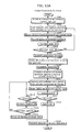
- FIGS. 4A to 4C are flowcharts of the processing of the terminal 100 A, the processing of the control device 200 , and the processing of the terminals 100 B to 100 F, respectively.
- FIG. 4A the processing performed by the terminal 100 A as a newly-connecting terminal is described.
- the terminal 100 A which is to be newly connected to the control device 200 , performs scanning to receive a beacon signal from the control device 200 (S 101 ).
- the terminal 100 A causes the receiving unit 101 to receive a beacon signal via each of frequency channels, by sequentially switching a frequency channel to another.
- the beacon processing unit 106 obtains, for each of the frequency channels, information indicating the number of existing terminals currently connected to the control device 200 using the corresponding frequency channel.
- the terminal 100 A selects one of the frequency channels, and causes the receiving unit 101 to receive acknowledgement packets from the already-connected terminals via the selected frequency channel (the processing is referred to also as “capturing of already-connected terminals”).
- the data processing unit 102 detects the number of the already-connected terminals using the frequency channel, based on the number of captured acknowledgement packets (S 102 ).
- the channel control unit 110 compares the number of the already-connected terminals detected using the captured acknowledgement packets to the number of the already-connected terminals indicated by the beacon signal received via the selected frequency channel (S 103 ).
- the number of the already-connected terminals indicated by the beacon signal is determined as equal to the number of the already-connected terminals detected using the acknowledgement packets (YES at S 103 ), then it is determined that there is no hidden terminal for the newly-connecting terminal 100 A via the selected frequency channel.
- the terminal 100 A determines to use the selected frequency channel to wirelessly communicate with the control device 200 . Then, the selected-channel notification generation unit 104 causes the transmission unit 105 to transmit a selected-channel notification for notifying the control device 200 of the selected frequency channel (S 105 ).
- the terminal 100 A performs the steps S 102 and S 103 via the newly selected frequency channel.
- control device 200 Next, referring to FIG. 4B , the processing performed by the control device 200 is described.
- control device 200 transmits an acknowledgement packet transmission request to each of the already-connected terminals connected to the control device 200 via, for example, Ch 1 (S 106 ).
- control device 200 determines whether or not a selected-channel notification, which is transmitted when the newly-connecting terminal 100 A selects the frequency channel Ch 1 , is received from the newly-connecting terminal 100 A (S 107 ).
- the data processing unit 202 in the control device 200 causes the transmission unit 206 to transmit a selected-channel response in response to the selected-channel notification (S 109 ).
- control device 200 changes the frequency channel Ch 1 to Ch 2 (S 108 ). After that, the control device 200 performs the steps S 106 and S 107 again via Ch 2 .
- each of the terminals 100 B to 100 F determines, on the frequency channel used by the terminal, whether or not an acknowledgement packet transmission request is received from the control device 200 (S 110 ).
- each of the terminals 100 B and 100 C determines whether or not the acknowledgement packet transmission request is received via Ch 2 .
- each of the terminals 100 D to 100 F determines whether or not the acknowledgement packet transmission request is received via Ch 1 .
- the terminals 100 B to 100 F transmit respective acknowledgement packets by which the newly-connecting terminal 100 A detects the already-connected terminals (S 111 ).
- the acknowledgment packet generation unit 103 in each of the terminals 100 B and 100 C uses Ch 2 to transmit an acknowledgement packet from the transmission unit 105 .
- the acknowledgment packet generation unit 103 in each of the terminals 100 D to 100 F uses Ch 1 to transmit an acknowledgement packet from the transmission unit 105 .
- each of the terminals 1008 to 100 F returns to S 110 .
- the beacon signal transmitted by the control device 200 is added with information indicating the number of already-connected terminals using the corresponding frequency channel.
- control device 200 causes the already-connected terminals to transmit acknowledgement packets to ensure the communication.
- the terminal 100 A which is to be newly connected to the control device 200 can detect existence of a hidden terminal and therefore reduce a possibility of the hidden terminal problem.
- Embodiment 1 it has been described in Embodiment 1 that in the wireless communication system as shown in FIG. 1 , a frequency channel without hidden terminal is selected from among a plurality of frequency channels, but the present invention is not limited to the above.
- the present invention offers the same effects also by selecting a control device without hidden terminal from among a plurality of control devices.
- an acknowledgement packet may be used to merely detect which terminal connected to the wireless communication system transmits the acknowledge packet.
- the acknowledgement packet may include only a preamble for signal synchronization or the like in the physical layer, a network ID indicating a connecting network, and a terminal address.
- FIG. 5 is a configuration example of a wireless communication system according to Embodiment 2.
- the wireless communication system in FIG. 5 includes: the control device 200 that controls a wireless network; and terminals 300 A to 300 F that wirelessly communicate with the control device 200 under the control of the control device 200 .
- FIG. 6 is a functional block diagram of a representative communication terminal 300 according to Embodiment 3.
- the receiving unit 101 , the transmission unit 105 , the beacon processing unit 106 , the data processing unit 102 , the acknowledgment packet generation unit 103 , and the selected-channel notification generation unit 104 have the same structures as described in Embodiment 1.
- An example of a channel control unit 310 according to Embodiment 2 is described in detail with reference to FIG. 6 .
- the channel control unit 310 shown in FIG. 6 includes an obtainment unit 311 , a capturing unit (third detection unit) 312 , a detection unit 313 , and a selection unit 314 .
- the obtainment unit 311 Based on a beacon signal, the obtainment unit 311 obtains the number of already-connected terminals connected to the control device 200 via each of the frequency channels.
- the capturing unit 312 captures packets (“acknowledgement packets” in Embodiment 2) transmitted from the already-connected terminals in the communication area, and thereby detects the number of already-connected terminals from which signals can arrive at the representative terminal 300 .
- the detection unit 313 compares the actual number of already-connected terminals which is obtained from the obtainment unit 311 to the number of already-connected terminals which is the number of terminals (source terminal) transmitting packets successfully captured by the capturing unit 312 , so as to detect the number of hidden terminals.
- the selection unit 314 selects a frequency channel to be connected.
- FIGS. 7A to 7C are flowcharts of the processing of the terminal 300 A, the processing of the control device 200 , and the processing of the terminals 300 B to 300 F, respectively.
- the terminal 300 A which is to be newly connected to the control device 200 initializes, to init_scan_ch, a value of a frequency channel ch on which a beacon signal is scanned (S 201 ).
- the terminal 300 A performs scanning to receive a beacon signal from the control device 200 , thereby receiving the beacon signal (S 202 ).
- the terminal 300 A obtains information Nch indicating the number of already-connected terminals currently connected to the control device 200 (S 203 ).
- the terminal 300 A sets a value of ch to next_scan_ch to change the frequency channel ch for scanning a beacon signal to another (S 204 ).
- the terminal 300 A determines whether or not the value of ch is last_scan_ch (S 205 ). If it is determined that the value of ch is not yet last_scan_ch (NO at S 205 ), the terminal 300 A scans a beacon signal via a next frequency channel ch (S 202 ).
- the terminal 300 A determines that the beacon scanning is completed and transmits, to the control device 200 , a connection request for requesting network connection (S 206 ).
- the terminal 300 A receives, from the control device 200 , a connection response indicating that the connection is permitted, and therefore determines that the connection is completed (S 207 ).
- the terminal 300 A initializes, to init_capture_ch the value of the frequency channel ch for capturing already-connected terminals already connected to the control device 200 (S 208 ), and then captures acknowledgement packets transmitted from the already-connected terminals (S 209 ).
- the terminal 300 A obtains the number Cch of already-connected terminals by the capturing (S 210 ). Then, the terminal 300 A subtracts Cch which is obtained by the capturing, from the number Nch of already-connected terminals which is obtained based on a beacon, thereby detecting the number of hidden terminals from each of which a signal does not arrive at the terminal 300 A (S 211 ).
- the terminal 300 A sets the value of ch to next_capture_ch in order to change the frequency channel ch for capturing already-connected terminals to another (S 212 ).
- the terminal 300 A determines whether or not the value of ch is last_capture_ch (S 213 ). If it is determined that the value of ch is not yet last_capture_ch (NO at S 213 ), then the terminal 300 A captures already-connected terminals via a next frequency channel ch (S 209 ).
- the terminal 300 A determines that the already-connected terminal capturing is completed for all of the frequency channels, and selects ch on which the number Hch of hidden terminals is minimum, as a frequency channel ch for wireless communication with the control device 200 (S 214 ).
- the terminal 300 A transmits a selected-channel notification to notify the control device 200 of ch selected at S 214 for communication (S 215 ).
- control device 200 Next, with reference to FIG. 7B , the processing performed by the control device 200 is described.
- control device 200 receives a connection request from the newly-connecting terminal 300 A (S 216 ).
- control device 200 transmits a connection response to the terminal 300 A to permit the connection request (S 217 ).
- control device 200 initializes, to init_capture_ch, a value of the frequency channel ch on which an acknowledgement packet transmission request is to be transmitted (S 218 ).
- the control device 200 transmits the acknowledgement packet transmission request for requesting each of the already-connected terminals to transmit an acknowledgement packet (S 219 ).
- control device 200 sets the value of ch to next_capture_ch to switch the frequency channel ch on which the acknowledgement packet transmission request is to be transmitted (S 220 ).
- control device 200 determines whether or not the value of ch is last_capture_ch (S 221 ). If it is determined that the value of ch is not yet last_capture_ch (NO at S 221 ), then the control device 200 transmits an acknowledgement packet transmission request via a next frequency channel ch (S 219 ).
- the control device 200 determines that the terminal 300 A has completed the already-connected terminal capturing, and transmits a selected-channel response in response to the selected-channel notification transmitted from the terminal 300 A (S 222 ).
- FIG. 8 is a diagram showing an example of a connection sequence when the terminal 300 A attempts to be connected to the control device 200 according to Embodiment 2.
- the connection sequence according to the present embodiment includes main steps: a scan step and a capture step.
- the terminal 300 A scans a beacon signal transmitted as broadcast from the control device 200 at certain time intervals.
- an available time period (beacon interval) during which signal exchange is possible via the corresponding frequency channel is assigned. Therefore, the terminal 300 A causes the receiving unit 101 to receive a beacon signal, while switching a frequency channel to another once at the available time period.
- the terminal 300 A scans a beacon signal transmitted from the control device 200 via each of the frequency channels, and transmits a connection request to the control device 200 .
- This connection request serves also as an order signal for ordering each of the other communication terminals 300 B to 300 F performing wireless communication using the corresponding frequency channel, to transmit an acknowledgement packet transmission request (request signal).
- any desired one of the frequency channels may be selected in transmitting the connection request.
- the selected frequency channel may be temporal and different from a frequency channel eventually determined based on the number of hidden terminals.
- the terminal 300 A obtains information indicating that three already-connected terminals are connected via Ch 1 and two already-connected terminals are connected via Ch 1 .
- the control device 200 transmits a connection response to the terminal 300 A to permit connection.
- the terminal 300 A detects hidden terminals and thereby selects a frequency channel by which influence of hidden terminal problem can be reduced.
- the control device 200 transmits an acknowledgement packet transmission request to each of the already-connected terminals 300 D to 300 F connected to Ch 1 .
- the control device 200 may broadcast the acknowledgement packet transmission request via Ch 1 .
- each of the already-connected terminals 300 D to 300 F transmits an acknowledgement packet.
- each of the terminals 300 D to 300 F may broadcast the acknowledgement packet via Ch 1 .
- the terminal 300 A captures the acknowledgement packets transmitted from the already-connected terminals via Ch 1 .
- the terminal 300 A captures the acknowledgement packets transmitted from the terminals 300 E and 300 F via Ch 1 , but fails to capture an acknowledgement packet from the terminal 300 D. Under the assumption, the terminal 300 A can detect two already-connected terminals via Ch 1 .
- the control device 200 uses Ch 2 to broadcast an acknowledgement packet transmission request to the already-connected terminals 300 B and 300 C connected to Ch 2 .
- each of the already-connected terminals 300 B and 300 C broadcasts an acknowledgement packet via Ch 2 .
- the terminal 300 A captures the acknowledgement packets transmitted from the already-connected terminals via Ch 2 .
- the terminal 300 A can capture the acknowledgement packets from the terminals 300 B and 300 C via Ch 2 .
- the terminal 300 A can detect two already-connected terminals via Ch 2 .
- the terminal 300 A selects a frequency channel to be used for communication, based on the information indicating the number of already-connected terminals which is indicated by a beacon signal and the information indicating the number of already-connected terminals which is obtained by the capturing unit 312 .
- the detection unit 313 determines that the number of hidden terminals on Ch 1 is one.
- the detection unit 313 determines that the number of hidden terminals on Ch 2 is 0.
- the terminal 300 A selects Ch 2 as a frequency channel to be used for communication with the control device 200 .
- the terminal 300 A transmits, to the control device 200 , a selected-channel notification for notifying that Ch 2 is to be used as a communication frequency channel.
- the control device 200 transmits a selected-channel response to the terminal 300 A in response to the selected-channel notification transmitted from the terminal 300 A.
- the control device 200 transmits an acknowledgement packet transmission request to each of the already-connected terminals 300 B to 300 F, and each of the terminals 300 B to 300 F transmits a acknowledgement packet.
- each of the terminals 300 B to 300 F surely transmits an acknowledgement packet, so that, even in a wireless communication systems performing access control by CSMA/CA, the terminal 300 A as a newly-connecting can capture the number of already-connected terminals.
- the terminal 300 A can detect the number of already-connected terminals.
- the newly-connecting terminal can detect: the number of already-connected terminals (source terminals) transmitting signals arrived at the newly-connecting terminal; and the actual number of already-connected terminals. It is therefore possible to recognize a frequency channel without any hidden terminal to increase a possibility of avoiding hidden terminal problem.
- the number of already-connected terminals or a traffic amount for each frequency channel is not statistically measured, so that it is not necessary to take a long time to obtain correct statistic.
- the method of measuring statistics of a frequency channel it is possible to shorten a time required to detect already-connected terminals.
- the number of frequency channels enabling communication is increased, it is possible to prevent the increase of a time required to detect already-connected terminals.
- FIG. 9 is a frequency channel selection method in the case where there are a plurality of frequency channels each having the same minimum hidden terminals.
- the terminal 300 D is a hidden terminal on Ch 1 while the terminal 300 C is a hidden terminal on Ch 2 .
- the terminal 300 A selects a frequency channel with a less traffic amount of the hidden terminal. In the case of FIG. 9 , it is determined that the terminal 300 D on Ch 1 has a less traffic amount. As a result, Ch 1 is selected.
- the control device 200 measures a traffic amount every predetermined time for each of the terminals 300 B to 300 F, based on the signal amount exchanged among the terminals 300 B to 300 F.
- the terminal 300 A adds the information for identifying a frequency channel candidate (Ch 1 , Ch 2 ) and the information for identifying a hidden terminal (terminal 300 D on Ch 1 , terminal 300 C on Ch 2 ) for each of the frequency channels are added to a selected-channel notification to be provided to the control device 200 .
- the control device 200 compares the traffic amount of the terminal 300 D to the traffic amount of the terminal 300 C which are added in the selected-channel notification, and then notifies, by using a selected-channel response, the terminal 300 A to select Ch 1 used by the terminal 300 D with a less traffic amount.
- the traffic amount to be compared may be an average value, a maximum value, or a sum of a traffic amount measured in a certain time period, for example.
- the “certain time period” may be several most-recent beacon intervals, for example.
- acknowledgement packet transmission request in the present embodiment may be transmitted by either broadcast or uncast.
- each of the already-connected terminals may transmit an acknowledgement packet by CSMA/CA in the autonomous distributed manner, it is also possible to set a transmission order for the already-connected terminals by Time Division Multiple Accesses (TDMA) or by setting different backoff times for the respective terminals. By setting different transmission timings for respective already-connected terminals, it is possible to prevent collision between acknowledgement packets transmitted by the already-connected terminals. It is also possible to use Wideband Code Division Multiple Access (CDMA) and the like.
- TDMA Time Division Multiple Accesses
- CDMA Wideband Code Division Multiple Access
- FIG. 10 is a configuration example of a wireless communication system according to Embodiment 3.
- the wireless communication system shown in FIG. 10 includes: a control device 500 that controls a wireless network; and terminals 400 A to 400 F that wirelessly communicate with the control device 500 under the control of the control device 500 .
- the communication terminal according to Embodiment 3 further includes a third detection unit. While the first detection unit is detecting the number of the other communication terminals on each of the frequency channels, the third detection unit causes the communication unit to receive signals transmitted from the communication terminals (source terminals). Therefore, the third detection unit detects the number of terminals (source terminals) transmitting the signals for each of the frequency channels. Then, the channel control unit causes the communication unit to transmit, to the control device, an order signal for ordering the control device to transmit a request signal sequentially to frequency channels in order of a less difference between (a) the number of communication terminals (source terminals) included in the notification signal and (b) the number of transmitting terminals (source terminals).
- the control device causes the communication unit to receive an order signal including the number of communication terminals for each of the frequency channels. The number of communication terminals has already been found by a newly-connecting communication terminal. Then, the control device causes the second signal generation unit to generate a request signal in order of frequency channels with a less difference between the number of communication terminals which is stored in the management unit and the number of communication terminals which is included in the order signal.
- FIG. 11 is a functional block diagram of a representative communication terminal 400 according to Embodiment 3.
- the same reference numerals in FIG. 6 are assigned to the identical structural elements in FIG. 11 , so that these identical structural elements are not described again below.
- the communication terminal 400 shown in FIG. 11 differs from the communication terminal 300 shown in FIG. 6 in the functions of the capturing unit 412 and the detection unit 413 and in further including a terminal number notification generation unit 407 .
- the capturing unit 412 has not only the functions of the capturing unit 312 shown in FIG. 6 but also a function of detecting already-connected terminals during scanning a beacon signal. More specifically, during scanning a beacon signal, the capturing unit 412 captures packets transmitted from the other communication terminals and finds terminals (source terminals) transmitting the packets.
- the “packets transmitted from the other communication terminals” may include any data and may be transmitted to anywhere. In other words, the capturing unit 412 captures arbitrary signals incidentally transmitted from the other communication terminals and detects the existence of the communication terminals.
- the terminal number notification generation unit 407 generates a connection request (order signal) including the number of already-connected terminals which the capturing unit 412 has detected for each of the frequency channels during scanning of a beacon signal, and then causes the transmission unit 105 to transmit the connection request.
- the detection unit 413 has not only the functions of the detection unit 313 shown in FIG. 6 but also a timer function of controlling a time period for capturing acknowledgement packets.
- FIG. 12 is a functional block diagram of the control device 500 according to Embodiment 3.
- the same reference numerals in FIG. 3 are assigned to the identical structural elements in FIG. 12 , so that these identical structural elements are not described again below.
- the control device 500 shown in FIG. 12 differs from the control device 200 shown in FIG. 3 in the functions of the transmission request generation unit 504 and in further including a channel control unit 505 .
- the transmission request generation unit 504 has not only the functions of the transmission request generation unit 204 shown in FIG. 3 but also a timer function of controlling a time period during which the newly connecting terminal captures acknowledgement packets.
- the channel control unit 505 determines an order of selecting frequency channels to transmit an acknowledgement packet transmission request, based on a captured-terminal number notification notified from the communication terminal 400 .
- FIGS. 13A to 13C are flowcharts of the processing of the newly-connecting terminal 400 A, the processing of the control device 500 , and the processing of the terminals 400 B to 400 F according to Embodiment 3, respectively.
- the terminal 400 A which is to be newly connected to the control device 500 initializes, to init_scan_ch, a value of a frequency channel ch on which a beacon signal is scanned (S 301 ).
- the terminal 400 A performs scanning to receive a beacon signal from the control device 500 , thereby receiving the beacon signal (S 302 ).
- the terminal 400 A uses a currently using frequency channel (initscan_ch) to obtain, from the beacon signal received at S 302 , the information Nch indicating the number of already-connected terminals connected to the control device 500 (S 303 ).
- initscan_ch a currently using frequency channel
- the capturing unit 412 in the terminal 400 A captures signals from the already-connected terminals during scanning the beacon signal from the control device 500 , and records the number of already-connected terminals captured in the scanning (S 304 ).
- the terminal 400 A sets a value of ch to next_scan_ch to change the frequency channel ch for scanning a beacon signal to another (S 305 ).
- the terminal 400 A determines whether or not the value of ch is last_scan_ch (S 306 ). If it is determined that the value of ch is not yet last_scan_ch (NO at S 306 ), the terminal 400 A scans a beacon signal via a next frequency channel ch (S 302 ).
- the terminal 400 A determines that the beacon scanning is completed and transmits, to the control device 500 , a connection request for requesting network connection (S 307 ).
- the terminal 400 A notifies the control device 500 of the number of already-connected terminals of each of the frequency channels which is recorded at S 304 (S 308 ).
- the number of already-connected terminals which is detected for each of the frequency channels may be transmitted being included in the connection request at S 307 , or may be transmitted as a signal different from the connection request.
- the terminal 400 A receives a connection response for permitting connection. Eventually, the terminal 400 A has been connected to the control device 500 (S 309 ).
- the terminal 400 A initializes, to init_capture_ch, a value of frequency channel ch on which the already-connected terminals connected to the control device 500 are captured (S 310 ).
- the terminal 400 A captures acknowledgement packets transmitted from the already-connected terminals (S 311 ).
- the detection unit 413 starts timer monitoring to control a time period for capturing acknowledgement packets.
- the terminal 400 A obtains the number Cch of already-connected terminals by the capturing (S 312 ).
- the terminal 400 A detects the number Hch of hidden terminals from which signals do not arrive at the terminal 400 A (S 313 ).
- the terminal 400 A determines whether or not the number Hch of hidden terminals is 0 (S 314 ).
- the terminal 400 A selects the currently using frequency channel ch as a frequency channel to be used for communication (S 315 ). Furthermore, the terminal 400 A transmits a selected-channel notification to the control device 500 to notify the frequency channel selected at S 315 (S 320 ).
- the terminal 400 A determines that there is an already-connected terminal not detected by the terminal 400 A, and further determines whether or not the time period for capturing already-connected terminals is timed out on the frequency channel ch (S 316 ).
- the terminal 400 A continues capturing of acknowledgement packets transmitted from already-connected terminals (S 311 ).
- the terminal 400 A sets the value of ch to next_capture_ch to which the frequency channel ch on which already-connected terminals are captured (S 317 ).
- the terminal 400 A determines whether or not the value of ch is last_capture_ch (S 318 ). If it is determined that the value of ch is not yet last_capture_ch (NO at S 318 ), then the terminal 400 A captures already-connected terminals via a next frequency channel ch (S 311 ). On the other hand, if it is determined that the value of ch is last_capture_ch (YES at S 318 ), then the terminal 400 A determines that the capturing of already-connected terminals is completed and selects a frequency channel having a minimum number Hch of hidden terminals as a frequency channel ch to be used for communication (S 319 ).
- control device 500 Next, with reference to FIG. 13B , the processing performed by the control device 500 is described.
- control device 500 receives a connection request from the terminal 400 A (S 321 ).
- the control device 500 determines an order of selecting frequency channels to transmit an acknowledgement packet transmission request, so that a frequency channel with a less number of already-connected terminals not yet captured by the 400 A is selected earlier (S 322 ).
- control device 500 transmits a connection response to the terminal 400 A to permit the connection request (S 323 ).
- control device 500 initializes, to init_capture_ch, a value of the frequency channel ch on which an acknowledgement packet transmission request is to be transmitted (S 324 ).
- control device 500 transmits the acknowledgement packet transmission request for requesting each of the already-connected terminals to transmit an acknowledgement packet (S 325 ).
- control device 500 determines whether or not the selected-channel notification is received from the terminal 400 A (S 326 ). If it is determined that the selected-channel notification is received (YES at S 326 ), then the control device 500 transmits a selected-channel response in response to the selected-channel notification transmitted from the terminal 400 A (S 327 ).
- the control device 500 determines whether or not the time period for capturing already-connected terminals by the terminal 400 A is timed out (S 328 ). If it is determined that the time period for capturing already-connected terminals remains (NO at S 328 ), then the control device 500 continues monitoring of a selected-channel notification (S 326 ).
- control device 500 sets the value of ch to next_capture_ch to switch the frequency channel ch on which an acknowledgement packet transmission request is transmitted (S 329 ).
- control device 500 determines whether or not the value of ch is last_capture_ch (S 330 ). If it is determined that the value of ch is not yet last_capture_ch (NO at S 330 ), then the control device 500 transmits an acknowledgement packet transmission request via a next frequency channel ch (S 325 ).
- control device 500 determines that the capturing of already-connected terminals is completed and proceeds to S 327 .
- FIG. 14 shows an example of a connection sequence when the terminal 400 A attempts to be connected to the control device 500 according to Embodiment 3.
- the connection sequence according to the present embodiment includes a scan step and a capture step.
- the terminal 400 A scans a beacon signal transmitted from the control device 500 at certain time intervals. At the same time as the beacon scanning, the terminal 400 A also captures signals from the already-connected terminals.
- the terminal 400 A After scanning a beacon signal transmitted from the control device 500 , the terminal 400 A transmits, to the control device 500 , a connection request and the number of already-connected terminals captured in the beacon scanning.
- the terminal 400 A is notified of that there are three already-connected terminals on Ch 1 and two already-connected terminals on Ch 2 . Since signals have been received from the terminals 400 C and 400 D, one already-connected terminal has been captured via the frequency channel Ch 1 , and one already-connected terminal has been captured via the frequency channel Ch 2 .
- the control device 500 transmits a connection response for permitting the terminal 400 A to be connected. Furthermore, based on the number of captured already-connected terminals for each of the frequency channels which is notified from the terminal 400 A, the control device 500 determines an order of selecting frequency channels to transmit an acknowledgement packet transmission request, so that a frequency channel with a less number of already-connected terminals not yet captured by the 400 A is selected earlier.
- the control device 500 switches frequency channels in order of Ch 2 and then Ch 1 , in order to transmit an acknowledgement packet transmission request.
- the control device 500 transmits an acknowledgement packet transmission request to each of the already-connected terminals 400 B and 400 C connected to Ch 2 .
- each of the already-connected terminals 400 B and 400 C transmits an acknowledgement packet.
- the terminal 400 A captures the acknowledgement packets transmitted from the already-connected terminals via Ch 2 .
- the terminal 400 A can capture acknowledgement packets from the already-connected terminals 400 B and 400 C via Ch 2 . In other words, the terminal 400 A can detect two already-connected terminals on Ch 2 .
- the terminal 400 A determines that all of already-connected terminals on Ch 2 have been captured, and then selects Ch 2 as a frequency channel to be used for communication.
- the terminal 400 A By using a selected-channel notification, the terminal 400 A notifies the control device 500 of that Ch 2 is selected as a frequency channel to be used for communication.
- the control device 500 transmits a selected-channel response to the terminal 400 A in response to the information notified from the terminal 400 A.
- the newly-connecting terminal captures also signals transmitted from the already-connected terminals in the beacon scanning. It is therefore possible to perform the already-connected terminal capturing by selecting frequency channels in order of decreasing the number of already-connected terminals not yet captured by the newly-connecting terminal. As a result, it is possible to shorten a time period for capturing already-connected terminals.
- connection to the frequency channel can shorten the time period for capturing already-connected terminals, because it is not necessary to capture already-connected terminals for all of the frequency channels.
- the already-connected terminal capturing is necessary only for the frequency channel Ch 2 , so that capturing for Ch 1 can be eliminated. As a result, it is possible to significantly shorten a time period for capturing already-connected terminals.
- a frequency channel is selected in the already-connected terminal capturing in order of decreasing the number of already-connected terminals not yet captured by the newly-connecting terminal, but the present invention is not limited to the above.
- the order of frequency channels in the capturing may be determined based on the situation of each of the frequency channels, such as signal power, interference power, or the number of accommodated terminals.
- the signal power may be measured by a beacon, a connection request, a connection response, or the like.
- the interference amount or the number of accommodated terminals for each of the frequency channels may be detected by the control device 500 .
- FIG. 15 is a configuration example of a wireless communication so system according to Embodiment 4.
- the wireless communication system shown in FIG. 15 includes: a control device 700 that controls a wireless network; and terminals 600 A to 600 F that wirelessly communicate with the control device 700 under the control of the control device 700 .
- the communication terminal according to Embodiment 4 further includes a third detection unit. While the first detection unit is detecting the number of the other communication terminals on each of the frequency channels, the third detection unit causes the communication unit to receive signals transmitted from the other communication terminals. Therefore, the third detection unit detects information for identifying terminals (source terminals) transmitting the signals for each of the frequency channels. Then, the channel control unit causes the communication unit to transmit an order signal for ordering the control device to transmit a request signal only to a communication terminal which the third detection unit cannot detect.
- FIG. 16 is a functional block diagram of a representative communication terminal 600 according to Embodiment 4.
- FIG. 11 The same reference numerals in FIG. 11 are assigned to the identical structural elements in FIG. 16 , so that these identical structural elements are not described again below.
- the communication terminal 600 shown in FIG. 16 differs from the communication terminal 400 shown in FIG. 11 in further including an address storage unit 607 and a generation unit 608 .
- the address storage unit 607 records addresses of captured already-connected terminals (information for identifying the already-connected terminals), while the capturing unit 412 is scanning a beacon signal.
- the generation unit 608 causes the transmission unit 105 to transmit, to the control device 500 , already-connected terminal address notification including addresses of the captured already-connected terminals.
- the addresses are stored in the address storage unit 607 .
- the control device further includes a channel control unit.
- the channel control unit causes the communication unit to receive the order signal including the information for indentifying the communication terminals which the newly-connecting communication terminal has already found, and causes the second signal generation unit to generate a request signal to be transmitted to only a communication terminal which the newly-connecting communication terminal cannot find.
- FIG. 17 is a functional block diagram of the control device 700 according to Embodiment 4.
- FIG. 12 The same reference numerals in FIG. 12 are assigned to the identical structural elements in FIG. 17 , so that these identical structural elements are not described again below.
- the control device 700 shown in FIG. 17 differs from the control device 500 shown in FIG. 12 in further including a control unit 705 .
- the control unit 705 determines an order of selecting frequency channels to transmit an acknowledgement packet transmission request, based on the address information of the captured already-connected terminals which is notified from the communication terminal 600 .
- FIGS. 18A to 18C are flowcharts of the processing of the newly-connecting terminal 600 A, the processing of the control device 700 , and the processing of the already-connected terminals 600 B to 600 F according to Embodiment 4, respectively.
- the terminal 600 A which is to be newly connected to the control device 700 initializes, to init_scan_ch, a value of a frequency channel ch on which a beacon signal is to be scanned (S 401 ).
- the terminal 600 A performs scanning to receive a beacon signal from the control device 700 , thereby receiving the beacon signal (S 402 ).
- the terminal 600 A obtains information Nch indicating the number of already-connected terminals currently connected to the control device 700 (S 403 ).
- the terminal 600 A captures signals from the already-connected terminals during scanning the beacon signal from the control device 700 , and records the number Sch of already-connected terminals captured in the scanning and addresses of the already-connected terminals (S 404 ).
- the terminal 600 A sets a value of ch to next_scan_ch to switch the frequency channel ch for scanning a beacon signal to another (S 405 ).
- the terminal 600 A determines whether or not the value of ch is last_scan_ch (S 406 ). If it is determined that the value of ch is not yet last_scan_ch (NO at S 406 ), the terminal 600 A performs beacon scanning via a next frequency channel ch (S 402 ).
- the terminal 600 A determines that the beacon scanning is completed and transmits, to the control device 700 , a connection request for requesting network connection (S 407 ).
- the terminal 600 A notifies the control device 700 of the addresses of the captured already-connected terminals on each of the frequency channels which are recorded at S 404 (S 408 ). This notification may be included in the connection request at S 407 , or may be transmitted as a different signal.
- the terminal 600 A receives a connection response for permitting connection, thereby completing the connection (S 409 ).
- the terminal 600 A initializes, to init_capture_ch, a value of frequency channel ch on which the already-connected terminals connected to the control device 700 are captured (S 410 ).
- the terminal 600 A captures acknowledgement packets transmitted from the already-connected terminals (S 411 ).
- the terminal 600 A obtains the number Cch of already-connected terminals by the capturing (S 412 ).
- the terminal 600 A detects the number Hch of hidden terminals from which signals do not arrive at the terminal 600 A (S 413 ).
- the terminal 600 A determines whether or not the number Hch of hidden terminals is 0 (S 414 ). If it is determined that the number Hch of hidden terminals is 0 (YES at S 414 ), then the terminal 600 A selects the currently using frequency channel ch as a frequency channel to be used for communication (S 415 ). Then, the terminal 600 A causes the transmission unit 105 to transmit a selected-channel notification to the control device 700 to notify the frequency channel selected at S 415 (S 420 ).
- the terminal 600 A determines that there is an already-connected terminal not yet detected by the terminal 600 A, and further determines whether or not a time period required for capturing already-connected terminals is timed out on the frequency channel ch (S 416 ). On the other hand, if it is determined that the time period for capturing already-connected terminals remains (No at S 416 ), then the terminal 600 A proceeds to S 411 .
- the terminal 600 A sets the value of ch to next_capture_ch to switch the frequency channel ch on which already-connected terminals are captured (S 417 ).
- the terminal 600 A determines whether or not the value of ch is last_capture_ch (S 418 ). If it is determined that the value of ch is not yet last_capture_ch (NO at S 418 ), then the terminal 600 A captures already-connected terminals via a next frequency channel ch (S 411 ).
- the terminal 600 A determines that the capturing of already-connected terminals is completed and selects a frequency channel ch having a minimum number Hch of hidden terminals as a frequency channel ch to be used for communication (S 419 ).
- control device 700 receives a connection request transmitted from the terminal 600 A (S 421 ).
- the control device 700 determines an order of selecting frequency channels to transmit an acknowledgement packet transmission request, so that a frequency channel with a less number of already-connected terminals not yet captured by the 600 A is selected earlier (S 422 ).
- control device 700 transmits a connection response to the terminal 600 A to permit the connection request (S 423 ).
- control device 700 initializes, to init_capture_ch, a value of the frequency channel ch on which an acknowledgement packet transmission request is to be transmitted (S 424 ).
- the control device 700 transmits a transmission request only to an already-connected terminal which the newly-connecting terminal has not yet captured (S 425 ).
- control device 700 determines whether or not the selected-channel notification is received from the terminal 600 A (S 426 ). If it is determined that the selected-channel notification is received (YES at S 426 ), then the control device 700 transmits a selected-channel response in response to the selected-channel notification transmitted from the terminal 600 A (S 427 ).
- the control device 700 determines whether or not the time period for capturing already-connected terminals by the terminal 600 A is timed out (S 428 ). If it is determined that the time period for capturing already-connected terminals remains (NO at S 428 ), then the control device 700 continues monitoring of a selected-channel notification (S 426 ).
- control device 700 sets the value of ch to next_capture_ch to switch the frequency channel ch on which an acknowledgement packet transmission request is transmitted (S 429 ).
- control device 700 determines whether or not the value of ch is last_capture_ch (S 430 ). If it is determined that the value of ch is not yet last_capture_ch (NO at S 430 ), then the control device 700 transmits an acknowledgement packet transmission request via a next frequency channel ch (S 425 ).
- control device 700 determines that the capturing of already-connected terminals is completed and proceeds to S 427 .
- FIG. 19 shows an example of a connection sequence when the terminal 600 A attempts to be connected to the control device 700 according to Embodiment 4.
- the connection sequence according to the present embodiment includes a scan step and a capture step.
- the terminal 600 A scans a beacon signal transmitted from the control device 700 at certain time intervals. At the same time as the beacon scanning, the terminal 600 A also captures signals from the already-connected terminals.
- the terminal 600 A After scanning a beacon signal transmitted from the control device 700 , the terminal 600 A transmits, to the control device 700 , a connection request and an address notification of the already-connected terminals captured in the beacon scanning.
- the terminal 600 A is notified of that there are three already-connected terminals on Ch 1 and two already-connected terminals on Ch 2 .
- addresses of the terminals 600 C and 600 D are transmitted to the control device 700 .
- the control device 700 transmits, to the terminal 600 A, a connection response for permitting connection.
- the control device 700 determines an order of selecting frequency channels to transmit an acknowledgement packet transmission request, so that a frequency channel with a less number of already-connected terminals not yet captured by the 600 A is selected earlier.
- the control device 700 switches frequency channels in order of Ch 2 and then Ch 1 , in order to transmit an acknowledgement packet transmission request.
- control device 700 After being connected to the terminal 600 A, the control device 700 transmits an acknowledgement packet transmission request to each of the already-connected terminals connected to Ch 2 .
- the control device 700 transmits an acknowledgement packet transmission request only to the already-connected terminal 600 B.
- the already-connected terminal 600 B transmits an acknowledgement packet.
- the terminal 600 A captures the acknowledgement packet transmitted from the already-connected terminal via Ch 2 .
- the terminal 600 A can capture an acknowledgement packet transmitted from the terminal 600 B via Ch 2 .
- the terminal 600 A can detect two already-connected terminals on Ch 2 .
- the terminal 600 A determines that all of the already-connected terminals on Ch 2 have been captured, and then selects Ch 2 as a frequency channel to be used for communication.
- the terminal 600 A transmits, to the control device 700 , a selected-channel notification for notifying that Ch 2 is selected as a frequency channel to be used for communication.
- the control device 700 transmits a selected-channel response to the terminal 600 A in response to the selected-channel notification transmitted from the terminal 600 A.
- the newly-connecting terminal captures also signals transmitted from the already-connected terminals in the beacon scanning, and notifies the control device of the addresses of the captured already-connected terminals. Therefore, it is possible to transmit an acknowledgement packet transmission request only to an already-connected terminal which the newly-connecting terminal cannot scan. As a result, traffic caused by the acknowledgement packet exchange is reduced, and therefore a time period for capturing already-connected terminals can be shortened.
- a communication terminal further includes a request signal generation unit.
- the request signal generation unit causes the communication unit to transmit a request signal while a using frequency channel is sequentially switched to another.
- the request signal is for requesting each of the other communication terminals performing wireless communication via the using frequency channel to transmit an acknowledgement signal.
- FIG. 20 is a configuration example of a wireless communication system according to Embodiment 5.
- the wireless communication system shown in FIG. 20 includes: a control device 900 that controls a wireless network; and terminals 800 A to 800 F that wirelessly communicate with the control device 900 under the control of the control device 900 .
- the structure of each of the terminals 800 A to 800 F is the same as that of the communication terminal 800 shown in FIG. 20 .
- a communication terminal further includes a signal generation unit.
- the signal generation unit generates a request signal and causes the communication unit to transmit the request signal while a using frequency channel is sequentially switched to another.
- the request signal is for requesting each of the other communication terminals performing wireless communication via the using frequency channel to transmit an acknowledgement signal.
- FIG. 21 is a functional block diagram of a representative communication terminal 800 according to Embodiment 5.
- FIG. 11 The same reference numerals in FIG. 11 are assigned to the identical structural elements in FIG. 21 , so that these identical structural elements are not described again below.
- the communication terminal 800 shown in FIG. 21 differs from the communication terminal 400 shown in FIG. 11 in further comprising a transmission request generation unit (signal generation unit) 807 .
- the transmission request generation unit 807 generates a request signal for requesting the other communication terminals to transmit acknowledgement signals, causes the transmission unit 105 to transmit the generated request signal.
- FIG. 22 is a functional block diagram of the control device 900 according to Embodiment 5.
- the control device 900 shown in FIG. 22 differs from the control device 200 shown in FIG. 3 in that the transmission request generation unit 204 is not included.
- FIGS. 23A to 23C are flowcharts of the processing of the newly-connecting terminal 800 A, the processing of the control device 900 , and the processing of the already-connected terminals 800 B to 800 F according to Embodiment 5, respectively.
- the terminal 800 A which is to be newly connected to the control device 900 , performs scanning to receive a beacon signal from the control device 900 , and obtains, from the received beacon signal, the number of already-connected terminals currently connected to the control device 900 (S 501 ).
- the terminal 800 A transmits an acknowledgement packet transmission signal to the already-connected terminals (S 502 ).
- the terminal 800 A captures the acknowledgement packets transmitted from the already-connected terminals, and detects the number of already-connected terminals based on the number of the captured acknowledgement packets (S 503 ).
- the terminal 800 A compares the number of already-connected terminals which is added to the beacon signal to the number of already-connected terminals which is detected based on the acknowledgement packets, and thereby determines existence of hidden terminal (S 504 ).
- the terminal 800 A determines that communication uses the frequency channel, and transmits, to the control device 900 , a selected-channel notification for notifying the selected frequency channel (S 506 ).
- the terminal 800 A determines that there is a hidden terminal, and therefore switches the frequency channel to another (S 505 ).
- control device 900 Next, with reference to FIG. 23B , the processing performed by the control device 900 is described.
- the control device 900 determines whether or not a selected-channel notification is received (S 507 ). If it is determined that the selected-channel notification is received (YES at S 507 ), then the control device 900 transmits a selected-channel response in response to the selected-channel notification (S 509 ). On the other hand, if it is determined that the selected-channel notification is not received (NO at S 507 ), then the control device 500 switches the using frequency channel to another (S 508 ).
- FIG. 24 shows an example of a connection sequence when the terminal 800 A attempts to be connected to the control device 900 according to Embodiment 5.
- the connection sequence according to the present embodiment includes a scan step and a capture step.
- the terminal 800 A scans a beacon signal transmitted from the control device 900 at certain time intervals. After scans a beacon signal transmitted from the control device 900 , the terminal 800 A transmits a connection request to the control device 900 .
- the control device 900 transmits, to the terminal 800 A, a connection response for permitting connection.
- the terminal 800 A After being connected to the control device 900 , the terminal 800 A broadcasts an acknowledgement packet transmission request via Ch 1 .
- each of the already-connected terminals on Ch 1 transmits an acknowledgement packet.
- the transmission request transmitted from the terminal 800 A arrives at the terminal 800 D and 800 E, but not the terminal 800 F. Therefore, only the terminals 800 D and 800 E transmit their acknowledgement packets.
- the terminal 800 A captures the acknowledgement packets transmitted from the already-connected terminals via Ch 1 .
- the terminal 800 A captures packets transmitted from the two already-connected terminals connected on Ch 1 .
- the information indicating the number of already-connected terminals which is included in the beacon signal indicates three terminals, while the information indicating the number of already-connected terminals which is obtained by capturing the packets transmitted from the already-connected terminals indicates two terminals.
- the terminal 800 A determines that there is one hidden terminal on Ch 1 , and therefore proceeds to a next frequency channel (Ch 2 ).
- the terminal 800 A broadcasts an acknowledgement packet transmission request via Ch 2 .
- each of the already-connected terminals on Ch 2 transmits an acknowledgement packet.
- the transmission request transmitted from the terminal 800 A arrives at the terminals 800 B and 800 C. Therefore, only the terminals 800 D and 800 E transmit their acknowledgement packets.
- the terminal 800 A captures the acknowledgement packets transmitted from the already-connected terminals via Ch 2 .
- the terminal 800 A captures packets transmitted from the two already-connected terminals connected on Ch 2 .
- the information indicating the number of already-connected terminals which is included in the beacon signal indicates two terminals, while the information indicating the number of already-connected terminals which is obtained by capturing the packets transmitted from the already-connected terminals indicates two terminals.
- the terminal 800 A determines that there is no hidden terminal on Ch 2 , and therefore selects Ch 2 as a frequency channel to be used for communication.
- the terminal 800 A transmits, to the control device 900 , the selected-channel notification indicating that Ch 2 is selected as a frequency channel to be used for communication.
- the control device 900 transmits a selected-channel response to the terminal 800 A in response to the selected-channel notification transmitted from the terminal 800 A.
- the newly-connecting terminal transmits an acknowledgement packet transmission request so that the acknowledgement packet transmission request does not arrive at hidden terminals.
- the number of terminals transmitting acknowledgement packets is reduced. It is therefore possible to reduce a traffic for the packet exchange and reduce collision of acknowledgement packets transmitted from a plurality of already-connected terminals.
- the control device does not transmit an acknowledgement packet
- the newly-connecting terminal includes the transmission request generation unit that generates an acknowledgement packet transmission request.
- FIG. 25 shows the situation where transmission power used by a terminal 1000 A as a newly-connecting terminal to transmit an acknowledgement packet transmission request is limited enough to arrive at the control device 900 .
- the terminal 1000 A differs from the communication terminal 800 in FIG. 21 in the function of the detection unit 413 .
- the detection unit in the terminal 1000 A has not only the functions of the detection unit 413 in the communication terminal 800 but also a function of calculating a ratio of (a) the number of captured already-connected terminals which is detected by acknowledgement packets to (b) the number of already-connected terminals which is included in a beacon signal.
- acknowledgement packets are transmitted only from the terminals 800 B and 800 E.
- the terminal 1000 A calculates, for each of the frequency channels, a ratio of (a) the number of captured already-connected terminals which is detected by acknowledgement packets to (b) the number of already-connected terminals which is included in a beacon signal.
- the terminal 1000 A selects a frequency channel having a high ratio of the number of captured already-connected terminals.
- control device 900 knows a network topology such as positional relationships among the terminals 1000 A and 800 B to 800 F, it is possible to determine an already-connected terminal having a high possibility of being a hidden terminal for the newly-connecting terminal 1000 A. Therefore, it is also possible to transmit an acknowledgement packet transmission request to already-connected terminals in order of increasing a possibility of being a hidden terminal.
- the terminal 10 F when the terminal 10 A communicates with the control device 20 , the terminal 10 F has a highest possibility of being a hidden terminal. More specifically, since the terminal 10 F exists on a line extended from a straight line between the terminal 10 A and the control device 20 , the terminal 10 F is likely to be a hidden terminal for the terminal 10 A.
- the terminal 10 A needs to receive an acknowledge packet from only the terminal 10 F. If the terminal 10 A can detect arrival of the acknowledgement packet from the terminal 10 F, it can also detect that the other terminals cannot be hidden terminals at the same time.
- control device 900 does not detect the network topology, it is possible to expect the situation of the other terminals.
- a home network as shown in FIG. 7 as long as it is certain in which room each of terminals is placed, only a single representative terminal in each room transmits an acknowledgement packet. Thereby, the situation of the other terminals in the room can be predicted. As a result, it is possible to select a frequency channel having a low possibility of including a hidden terminal. In addition, it is possible to shorten a time period for capturing already-connected terminals.
- each of terminals in a room partitioned by walls as shown in FIG. 27 is correlated with the propagation status of a newly-connecting terminal. Therefore, an acknowledgement packet transmission request is to be transmitted to only one already-connected terminal in each room.
- a frequency channel is selected for each room, when a home appliance having a wireless communication device is connected in a network, it is possible to automatically register in which room the home appliance is placed. Moreover, since rooms use different frequency channels, it is easily multicast a signal to only a specific room when only home appliances in the specific room are to be operated at the same time.
- Embodiments 1 to 5 has been described for the case of a wireless communication network, but the present invention is not limited to the above.
- it may be another network using a plurality of frequency channels, such as Power Line Communications (PLC).
- PLC Power Line Communications
- Embodiments 1 to 5 are desirably combined.
- each of the embodiments is implemented into a Large Scale Integration (LSI) that is a typically integrated circuit. These may be integrated separately, or a part or all of them may be integrated into a single chip.
- the integrated circuit is referred to as a LSI, but the integrated circuit can be called an IC, a system LSI, a super LSI or an ultra LSI depending on their degrees of integration.
- the technique of integrated circuit is not limited to the LSI, and it may be implemented as a dedicated circuit or a general-purpose processor. It is also possible to use a Field Programmable Gate Array (FPGA) that can be programmed after manufacturing the LSI, or a reconfigurable processor in which connection and setting of circuit cells inside the LSI can be reconfigured.
- FPGA Field Programmable Gate Array
- Each of the embodiments may be a computer system including a microprocessor, a Read Only Memory (ROM), a Random Access Memory (RAM), a hard disk unit, a display unit, a keyboard, a mouse, and the like.
- the RAM or the hard disk unit holds a computer program.
- the microprocessor executes the computer program to cause each of the embodiments to perform its functions.
- the computer program consists of combinations of instruction codes for issuing instructions to the computer to execute predetermined functions.
- the system LSI is a super multi-function LSI that is a single chip into which a plurality of structural elements are integrated. More specifically, the system LSI is a computer system including a microprocessor, a ROM, a RAM, and the like. The RAM holds a computer program. The microprocessor is executed by the computer program to cause the system LSI to perform its functions.
- IC Integrated Circuit
- the IC card or the module is a computer system including a microprocessor, a ROM, a RAM, and the like.
- the IC card or the module may include the above-described super multi-function LSI.
- the microprocessor executes the computer program to cause the IC card or the module to perform its functions.
- the IC card or the module may have tamper resistance.
- the present invention may be the above-described method.
- the present invention may be a computer program causing a computer to execute the method, or digital signals indicating the computer program.
- the present invention may be a computer-readable recording medium on which the computer program or the digital signals are recorded.
- the computer-readable recording medium are a flexible disk, a hard disk, a Compact Disc (CD)-ROM, a magnetooptic disk (MO), a Digital Versatile Disc (DVD), a DVD-ROM, a DVD-RAM, a BD (Blue-ray® Disc), and a semiconductor memory.
- the present invention may be digital signals recorded on the recording medium.
- the computer program or the digital signals may be transmitted via an electric communication line, a wired or wireless communication line, a network represented by the Internet, data broadcasting, and the like.
- the present invention may be a computer system including a microprocessor operating according to the computer program and a memory storing the computer program.
- program or the digital signals may be recorded onto the recording medium to, be transferred, or may be transmitted via a network or the like, so that the program or the digital signals can be executed by a different independent computer system.
- the wireless communication system according to the present invention is useful for wireless communication or the like of selecting one of frequency channels or one of control devices to be used for the communication.
Landscapes
- Engineering & Computer Science (AREA)
- Computer Networks & Wireless Communication (AREA)
- Signal Processing (AREA)
- Mobile Radio Communication Systems (AREA)
Abstract
Description
- [PTL 1] Japanese Unexamined Patent Application Publication No. 2008-42922
- [NPL 1] “Kaiteiban 802.11 Kosoku Musen LAN Kyokasho” edited by Masahiro Morikura, Impress, Jan. 1, 2005 (pp. 89 to 91)
- 1, 2, 20, 200, 500, 700, 900 control device
- 10A, 10B, 10C, 10D, 10E, 10F, 100A, 100B, 100C, 100D, 100E, 100F, 300A, 300B, 300C, 300D, 300E, 300F, 400A, 400B, 400C, 400D, 400E, 400F, 600A, 600B, 600C, 600D, 600E, 600F, 800A, 800B, 800C, 800D, 800E, 800F, 1000A terminal
- 30A, 30B transmitting terminal
- 40 receiving terminal
- 100, 300, 400, 600, 800 communication terminal
- 101, 201 receiving unit
- 102, 202 data processing unit
- 103 acknowledgment packet generation unit
- 104 selected-channel notification generation unit
- 105, 206 transmission unit
- 106 beacon processing unit
- 110, 310, 410, 505 channel control unit
- 203 management unit
- 204, 504, 807 transmission request generation unit
- 205 beacon generation unit
- 311 obtainment unit
- 312, 412 capturing unit
- 313, 413 detection unit
- 314 selection unit
- 407 terminal number notification generation unit
- 607 address storage unit
- 608 generation unit
- 705 control unit
Claims (15)
Applications Claiming Priority (3)
| Application Number | Priority Date | Filing Date | Title |
|---|---|---|---|
| JP2010132408 | 2010-06-09 | ||
| JP2010-132408 | 2010-06-09 | ||
| PCT/JP2011/003226 WO2011155191A1 (en) | 2010-06-09 | 2011-06-08 | Communication terminal, control device, communication method, control method, program, and integrated circuit |
Publications (2)
| Publication Number | Publication Date |
|---|---|
| US20130039323A1 US20130039323A1 (en) | 2013-02-14 |
| US8953543B2 true US8953543B2 (en) | 2015-02-10 |
Family
ID=45097806
Family Applications (1)
| Application Number | Title | Priority Date | Filing Date |
|---|---|---|---|
| US13/642,581 Expired - Fee Related US8953543B2 (en) | 2010-06-09 | 2011-06-08 | Communication terminal, control device, communication method, control method, program, and integrated circuit |
Country Status (4)
| Country | Link |
|---|---|
| US (1) | US8953543B2 (en) |
| JP (1) | JP5576936B2 (en) |
| CN (1) | CN102934507B (en) |
| WO (1) | WO2011155191A1 (en) |
Families Citing this family (9)
| Publication number | Priority date | Publication date | Assignee | Title |
|---|---|---|---|---|
| JP6003514B2 (en) | 2012-03-01 | 2016-10-05 | ソニー株式会社 | Information processing apparatus, communication system, and channel setting method |
| JP5991635B2 (en) * | 2013-02-13 | 2016-09-14 | パナソニックIpマネジメント株式会社 | Power line carrier communication terminal and meter reading terminal |
| JP6045937B2 (en) * | 2013-02-22 | 2016-12-14 | 東京エレクトロン株式会社 | Group management system and program |
| EP3014936B1 (en) * | 2013-06-27 | 2017-05-17 | Telefonaktiebolaget LM Ericsson (publ) | Method and radio node for managing resources for d2d discovery in an ad-hoc radio communication network |
| JP6248434B2 (en) * | 2013-07-03 | 2017-12-20 | 富士通株式会社 | Wireless communication system, wireless base station, and wireless terminal |
| JP6152616B2 (en) * | 2013-07-05 | 2017-06-28 | パナソニックIpマネジメント株式会社 | Communication terminal and communication system |
| JP2019050584A (en) * | 2018-10-24 | 2019-03-28 | ヤマハ株式会社 | Wireless relay device, wireless relay method and program |
| WO2020144932A1 (en) * | 2019-01-08 | 2020-07-16 | ソニー株式会社 | Communication device and communication method |
| JP2020195065A (en) * | 2019-05-28 | 2020-12-03 | パナソニックIpマネジメント株式会社 | Communication system, communication device, program, and communication confirmation method |
Citations (7)
| Publication number | Priority date | Publication date | Assignee | Title |
|---|---|---|---|---|
| JP2002359864A (en) | 2001-06-01 | 2002-12-13 | Nec Corp | Method for switching attribute of mobile terminal station to base station |
| JP2007158765A (en) | 2005-12-06 | 2007-06-21 | Hitachi Communication Technologies Ltd | Wireless communication terminal and load distribution method for relay device thereof |
| JP2007274145A (en) | 2006-03-30 | 2007-10-18 | Oki Electric Ind Co Ltd | Wireless access control apparatus |
| US20070248044A1 (en) * | 2006-04-20 | 2007-10-25 | Tropos Networks, Inc. | Mobile access node channel selection within a mesh network |
| JP2008042922A (en) | 2006-08-08 | 2008-02-21 | Ntt Docomo Inc | Method and apparatus for selecting an access point in a wireless local network |
| US20110222486A1 (en) * | 2010-03-10 | 2011-09-15 | Cisco Technology, Inc. | Downlink OFDMA for Service Sets with Mixed Client Types |
| US20110299408A1 (en) * | 2010-06-04 | 2011-12-08 | Microsoft Corporation | Dynamic Channel and Transmission Rate Selection |
Family Cites Families (3)
| Publication number | Priority date | Publication date | Assignee | Title |
|---|---|---|---|---|
| US7599698B2 (en) * | 2003-12-29 | 2009-10-06 | Telefonaktiebolaget Lm Ericsson (Publ) | Network controlled channel information reporting |
| CN101483917A (en) * | 2008-01-10 | 2009-07-15 | 华为技术有限公司 | Frequency band access switching method, terminal and base station |
| CN101409801B (en) * | 2008-12-01 | 2011-05-04 | 宇龙计算机通信科技(深圳)有限公司 | Method and system for switching television channel |
-
2011
- 2011-06-08 WO PCT/JP2011/003226 patent/WO2011155191A1/en not_active Ceased
- 2011-06-08 JP JP2012519250A patent/JP5576936B2/en not_active Expired - Fee Related
- 2011-06-08 CN CN201180027635.5A patent/CN102934507B/en not_active Expired - Fee Related
- 2011-06-08 US US13/642,581 patent/US8953543B2/en not_active Expired - Fee Related
Patent Citations (7)
| Publication number | Priority date | Publication date | Assignee | Title |
|---|---|---|---|---|
| JP2002359864A (en) | 2001-06-01 | 2002-12-13 | Nec Corp | Method for switching attribute of mobile terminal station to base station |
| JP2007158765A (en) | 2005-12-06 | 2007-06-21 | Hitachi Communication Technologies Ltd | Wireless communication terminal and load distribution method for relay device thereof |
| JP2007274145A (en) | 2006-03-30 | 2007-10-18 | Oki Electric Ind Co Ltd | Wireless access control apparatus |
| US20070248044A1 (en) * | 2006-04-20 | 2007-10-25 | Tropos Networks, Inc. | Mobile access node channel selection within a mesh network |
| JP2008042922A (en) | 2006-08-08 | 2008-02-21 | Ntt Docomo Inc | Method and apparatus for selecting an access point in a wireless local network |
| US20110222486A1 (en) * | 2010-03-10 | 2011-09-15 | Cisco Technology, Inc. | Downlink OFDMA for Service Sets with Mixed Client Types |
| US20110299408A1 (en) * | 2010-06-04 | 2011-12-08 | Microsoft Corporation | Dynamic Channel and Transmission Rate Selection |
Non-Patent Citations (2)
| Title |
|---|
| International Search Report issued Sep. 6, 2011 in International (PCT) Application No. PCT/JP2011/003226. |
| M. Morikura et al., "Kaiteiban 802.11 Kosoku Musen LAN Kyokasho", the Impress Japan, Jan. 1, 2005, pp. 89-91, with partial English translation. |
Also Published As
| Publication number | Publication date |
|---|---|
| CN102934507A (en) | 2013-02-13 |
| WO2011155191A1 (en) | 2011-12-15 |
| JP5576936B2 (en) | 2014-08-20 |
| JPWO2011155191A1 (en) | 2013-08-01 |
| US20130039323A1 (en) | 2013-02-14 |
| CN102934507B (en) | 2016-10-12 |
Similar Documents
| Publication | Publication Date | Title |
|---|---|---|
| US8953543B2 (en) | Communication terminal, control device, communication method, control method, program, and integrated circuit | |
| US9210652B2 (en) | System and method for active scanning in multi-channel Wi-Fi system | |
| US9521587B2 (en) | System and method for determining a clear channel assessment threshold | |
| TWI487418B (en) | Scheduling and protection of quiet periods in a quiet zone for incumbent signal detection | |
| US20180279130A1 (en) | Enhanced channel selection in a network having multiple access points | |
| CN107925893B (en) | Wireless environment information collection system and method | |
| JP7138443B2 (en) | Method, apparatus and system for detecting interference | |
| US9544898B2 (en) | Coordinating base station downlink transmissions in unlicensed frequency bands | |
| CN104247310B (en) | For the time-controlled system and method for beacon transmissions | |
| TW201735689A (en) | Managing radio frequency spectrum usage by a wireless network node | |
| WO2012124113A1 (en) | Wireless base station device, wireless communication method for wireless base station device, and wireless communication system | |
| CN102457869A (en) | Transmission power control | |
| TWI636692B (en) | Method and apparatus for uplink transmission by using unlicensed spectrum | |
| JP6007743B2 (en) | Multihop communication terminal, multihop communication system, and multihop communication method | |
| CN113330808A (en) | Methods, apparatus, and device-readable media for scheduling transmissions in a wireless network | |
| US20190191463A1 (en) | Guard terminal apparatus, access point, radio communication apparatus, and transmission method | |
| CN103687021B (en) | Base station apparatus, radio communications system and communication means | |
| CN105101347A (en) | Communication method and device of wireless local network | |
| JP2013179555A (en) | Radio access control method and radio communication apparatus | |
| JP6351059B2 (en) | Wireless communication terminal | |
| JP4276150B2 (en) | Frequency channel selection method and radio packet communication apparatus for radio packet communication system | |
| Peng et al. | Cross-layer analysis for symbiotic Internet of Things over CSMA/CN networks |
Legal Events
| Date | Code | Title | Description |
|---|---|---|---|
| AS | Assignment |
Owner name: PANASONIC CORPORATION, JAPAN Free format text: ASSIGNMENT OF ASSIGNORS INTEREST;ASSIGNORS:OHNISHI, TOSHIAKI;ANDO, KAZUHIRO;NAKAE, HIRONORI;SIGNING DATES FROM 20120921 TO 20120925;REEL/FRAME:029854/0205 |
|
| STCF | Information on status: patent grant |
Free format text: PATENTED CASE |
|
| FEPP | Fee payment procedure |
Free format text: PAYOR NUMBER ASSIGNED (ORIGINAL EVENT CODE: ASPN); ENTITY STATUS OF PATENT OWNER: LARGE ENTITY |
|
| MAFP | Maintenance fee payment |
Free format text: PAYMENT OF MAINTENANCE FEE, 4TH YEAR, LARGE ENTITY (ORIGINAL EVENT CODE: M1551) Year of fee payment: 4 |
|
| AS | Assignment |
Owner name: SOVEREIGN PEAK VENTURES, LLC, TEXAS Free format text: ASSIGNMENT OF ASSIGNORS INTEREST;ASSIGNOR:PANASONIC CORPORATION;REEL/FRAME:047914/0675 Effective date: 20181012 |
|
| FEPP | Fee payment procedure |
Free format text: MAINTENANCE FEE REMINDER MAILED (ORIGINAL EVENT CODE: REM.); ENTITY STATUS OF PATENT OWNER: LARGE ENTITY |
|
| LAPS | Lapse for failure to pay maintenance fees |
Free format text: PATENT EXPIRED FOR FAILURE TO PAY MAINTENANCE FEES (ORIGINAL EVENT CODE: EXP.); ENTITY STATUS OF PATENT OWNER: LARGE ENTITY |
|
| STCH | Information on status: patent discontinuation |
Free format text: PATENT EXPIRED DUE TO NONPAYMENT OF MAINTENANCE FEES UNDER 37 CFR 1.362 |
|
| FP | Lapsed due to failure to pay maintenance fee |
Effective date: 20230210 |