US8937814B2 - Positioning structure, positioning securing structure and electronic device - Google Patents
Positioning structure, positioning securing structure and electronic device Download PDFInfo
- Publication number
- US8937814B2 US8937814B2 US13/548,951 US201213548951A US8937814B2 US 8937814 B2 US8937814 B2 US 8937814B2 US 201213548951 A US201213548951 A US 201213548951A US 8937814 B2 US8937814 B2 US 8937814B2
- Authority
- US
- United States
- Prior art keywords
- positioning
- plate
- shaped structure
- securing
- base portion
- Prior art date
- Legal status (The legal status is an assumption and is not a legal conclusion. Google has not performed a legal analysis and makes no representation as to the accuracy of the status listed.)
- Expired - Fee Related, expires
Links
Images


Classifications
-
- G—PHYSICS
- G06—COMPUTING OR CALCULATING; COUNTING
- G06F—ELECTRIC DIGITAL DATA PROCESSING
- G06F1/00—Details not covered by groups G06F3/00 - G06F13/00 and G06F21/00
- G06F1/16—Constructional details or arrangements
- G06F1/18—Packaging or power distribution
- G06F1/183—Internal mounting support structures, e.g. for supporting printed circuit boards
- G06F1/184—Mounting of motherboards
-
- F—MECHANICAL ENGINEERING; LIGHTING; HEATING; WEAPONS; BLASTING
- F16—ENGINEERING ELEMENTS AND UNITS; GENERAL MEASURES FOR PRODUCING AND MAINTAINING EFFECTIVE FUNCTIONING OF MACHINES OR INSTALLATIONS; THERMAL INSULATION IN GENERAL
- F16B—DEVICES FOR FASTENING OR SECURING CONSTRUCTIONAL ELEMENTS OR MACHINE PARTS TOGETHER, e.g. NAILS, BOLTS, CIRCLIPS, CLAMPS, CLIPS OR WEDGES; JOINTS OR JOINTING
- F16B37/00—Nuts or like thread-engaging members
- F16B37/08—Quickly-detachable or mountable nuts, e.g. consisting of two or more parts; Nuts movable along the bolt after tilting the nut
- F16B37/0807—Nuts engaged from the end of the bolt, e.g. axially slidable nuts
-
- F—MECHANICAL ENGINEERING; LIGHTING; HEATING; WEAPONS; BLASTING
- F16—ENGINEERING ELEMENTS AND UNITS; GENERAL MEASURES FOR PRODUCING AND MAINTAINING EFFECTIVE FUNCTIONING OF MACHINES OR INSTALLATIONS; THERMAL INSULATION IN GENERAL
- F16B—DEVICES FOR FASTENING OR SECURING CONSTRUCTIONAL ELEMENTS OR MACHINE PARTS TOGETHER, e.g. NAILS, BOLTS, CIRCLIPS, CLAMPS, CLIPS OR WEDGES; JOINTS OR JOINTING
- F16B5/00—Joining sheets or plates, e.g. panels, to one another or to strips or bars parallel to them
- F16B5/02—Joining sheets or plates, e.g. panels, to one another or to strips or bars parallel to them by means of fastening members using screw-thread
Definitions
- the instant disclosure relates to a positioning structure, a positioning securing structure and an electronic device, and more particularly, to a positioning structure for positioning a plate-shaped structure, a positioning securing structure for positioning and securing a plate-shaped structure, and an electronic device using a positioning securing structure.
- a plurality of conductive stand off is disposed on a case of computer device to serve as fixing components, and a plurality of through holes corresponding to the stand off is opened on the motherboard.
- the motherboard is placed on the stand off, and keeps a suitable distance from the case. Then, a plurality of bolts is used to pass through the through holes of the motherboard and then screwed on the stand off, such that the motherboard generates a suspension effect through using the stand off, so as to prevent the weld leg contacts on the back side of the motherboard from directly contacting the case to result in short circuit.
- One aspect of the instant disclosure relates to a positioning structure for positioning a plate-shaped structure, a positioning securing structure for positioning and securing a plate-shaped structure, and an electronic device using a positioning securing structure.
- One of the embodiments of the instant disclosure provides a positioning structure for positioning a plate-shaped structure having at least one positioning hole, the positioning structure comprising at least one positioning element corresponding to the at least one positioning hole, wherein the at least one positioning element includes: a placement portion for supporting the plate-shaped structure and a positioning portion extending toward a direction far away from the placement portion to form a hollow cylinder shape, wherein the positioning portion has an outer surrounding surface and a plurality of inner threads. Hence, the outer surrounding surface of the positioning portion of the at least one positioning element contacts with the inner surface of the at least one positioning hole, for positioning the positioning portion of the at least one position element in the at least one positioning hole.
- a positioning securing structure for positioning and securing a plate-shaped structure having at least one positioning hole
- the positioning securing structure comprising: a positioning structure and a securing structure.
- the positioning structure includes at least one positioning element corresponding to the at least one positioning hole, wherein the at least one positioning element includes a placement portion for supporting the plate-shaped structure and a positioning portion extending toward a direction far away from the placement portion to form a hollow cylinder shape, and the positioning portion has an outer surrounding surface and a plurality of inner threads.
- the securing structure includes at least one securing element corresponding to the at least one positioning element, wherein the at least one securing element has a plurality of outer threads securely mated with the inner threads of the positioning portion of the at least one positioning element. Hence, the outer surrounding surface of the positioning portion of the at least one positioning element contacts with the inner surface of the at least one positioning hole, for positioning the positioning portion of the at least one position element in the at least one positioning hole.
- an electronic device comprising: a casing structure, a plate-shaped structure, a positioning structure and a securing structure.
- the plate-shaped structure is disposed in the casing structure, wherein the plate-shaped structure has at least one positioning hole.
- the positioning structure is disposed in the casing structure, wherein the positioning structure includes at least one positioning element corresponding to the at least one positioning hole, wherein the at least one positioning element includes a placement portion for supporting the plate-shaped structure and a positioning portion extending toward a direction far away from the placement portion to form a hollow cylinder shape, and the positioning portion has an outer surrounding surface and a plurality of inner threads.
- the securing structure includes at least one securing element corresponding to the at least one positioning element, wherein the at least one securing element has a plurality of outer threads securely mated with the inner threads of the positioning portion of the at least one positioning element. Hence, the outer surrounding surface of the positioning portion of the at least one positioning element contacts with the inner surface of the at least one positioning hole, for positioning the positioning portion of the at least one position element in the at least one positioning hole.
- the positioning portion of the positioning element when the outer surrounding surface of the positioning portion of the positioning element is inserted into the positioning hole to contact with the inner surface of the positioning hole, the positioning portion of the position element can be positioned in the positioning hole, thus the positioning structure, the positioning securing structure and the electronic device can be used to accurately position and secure the plate-shaped structure.
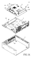
- FIG. 1A shows a perspective, exploded, schematic view of the electronic device according to the instant disclosure
- FIG. 1B shows an enlarged view taken on part A of FIG. 1A ;
- FIG. 1C shows a cross-sectional view taken along the section line 1 C- 1 C of FIG. 1B ;
- FIG. 2A shows a partial, perspective, exploded, schematic view of the electronic device according to the instant disclosure
- FIG. 2B shows an enlarged view taken on part A of FIG. 2A ;
- FIG. 2C shows a cross-sectional view taken along the section line 2 C- 2 C of FIG. 2B ;
- FIG. 3A shows a perspective, assembled, schematic view of the electronic device according to the instant disclosure
- FIG. 3B shows an enlarged view taken on part A of FIG. 3A ;
- FIG. 3C shows a cross-sectional view taken along the section line 3 C- 3 C of FIG. 3B .
- FIG. 1A is a perspective, exploded, schematic diagram
- FIG. 2A is a partial, perspective, exploded, schematic diagram
- FIG. 3A is a perspective, assembled, schematic diagram
- FIGS. 1B , 2 B and 3 B are enlarged diagrams
- FIGS. 1C , 2 C and 3 C are cross-sectional diagrams.
- the instant disclosure provides an electronic device Z comprises a casing structure 1 , a positioning structure 2 , a plate-shaped structure 3 and a securing structure 4 , where the plate-shaped structure 3 includes a plurality of electrical connectors 31 .
- the casing structure 1 may be a computer chassis for a computer host, thus the casing structure 1 may have a plurality of connector openings 10 formed in advance for respectively exposing the electrical connectors 31 of the plate-shaped structure 3 .
- the casing structure 1 used in this embodiment is merely an example and is not meant to limit the instant disclosure.
- the positioning structure 2 and the plate-shaped structure 3 can be disposed in the casing structure 1 , for example, the positioning structure 2 can be fixed in the casing structure 1 through many fixing elements (not shown).
- the method of fixing the positioning structure 2 in the casing structure 1 used in this embodiment is merely an example and is not meant to limit the instant disclosure.
- the positioning structure 2 includes two positioning elements 20 separated from each other, and the two positioning elements 20 separated from each other is set at a predetermined distance, where each positioning element 20 includes a base portion 20 A, an extending portion 20 B, a placement portion 20 C and a positioning portion 20 D.
- the base portion 20 A, the extending portion 20 B, the placement portion 20 C and the positioning portion 20 D can be integrally formed as a one-piece component.
- the extending portion 20 B can be inclinedly extended toward a direction far away from the base portion 20 A, for example, the extending portion 20 B can be extended inclinedly toward a direction from two face-to-face inner sides to a center line L to form a first surrounding portion having a top surface similar to an arch bridge shape.
- the placement portion 20 C is connected to the extending portion 20 B, thus when the plate-shaped structure 3 is placed on the placement portion 20 C and supported by the placement portion 20 C, the plate-shaped structure 3 being separated from the base portion 20 A is set at a predetermined distance.
- the placement portion 20 C can be extended surroundingly toward a direction from the extending portion 20 B to the center line L to form a second surrounding portion that is connected to the first surrounding portion and has a top surface shown as a plane shape, and the placement portion 20 C has a through opening 200 C.
- the positioning portion 20 D can be surroundingly, vertically and upwardly extended from the placement portion 20 C to form a third surrounding portion shown as a hollow cylinder shape that is connected to the second surrounding portion, that is to say, the positioning portion 20 D is extended toward the direction far away from the placement portion 20 C to form the hollow cylinder shape.
- the positioning portion 20 D has a through hole 200 D communicated with the through opening 200 C and a plurality of inner threads 201 D formed in the through hole 200 D, where the center line L is the center line of the through hole 200 D, and the number of the inner threads 201 D of the positioning portion 20 D ranges from 1.5 to 2 (1 thread means that the thread is formed around a circle on the positioning portion 20 D).
- the number of the inner threads 201 D of the positioning portion 20 D used in this embodiment is merely an example and is not meant to limit the instant disclosure.
- the base portion 20 A has a top surface and a bottom surface corresponding to the top surface.
- the positioning portion 20 D has an outer surrounding surface 202 D and an inner surrounding surface 203 D surrounded by the outer surrounding surface 202 D.
- the base portion 20 A has a thickness H defined between the top surface and the bottom surface of the base portion 20 A, the positioning portion 20 D has a thickness h defined between the inner surrounding surface 203 D and the outer surrounding surface 202 D of the positioning portion 20 D, and the thickness H of the base portion 20 A is substantially 2 to 3 times larger than the thickness h of the positioning portion 20 D.
- the relationship between the thickness H of the base portion 20 A and the thickness h of the positioning portion 20 D shown in this embodiment is merely an example and is not meant to limit the instant disclosure. Therefore, when the base portion 20 A is drawn upwardly to form the positioning portion 20 D and the inner threads 201 D are formed on the inner surrounding surface 203 D of the positioning portion 20 D by tapping, the structure strength of the positioning portion 20 D can still be maintained at a predetermined value due to the design of the multiple relationship between the thickness H of the base portion 20 A and the thickness h of the positioning portion 20 D.
- FIGS. 2A , 2 B and 2 C where FIG. 2B shows an enlarged view taken on part A of FIG. 2A , and FIG. 2C shows a cross-sectional view taken along the section line 2 C- 2 C of FIG. 2B .
- the plate-shaped structure 3 (such as a motherboard) can be disposed on the placement portion 20 C of each positioning element 20 .
- the plate-shaped structure 3 has two positioning holes 30 formed on the same plane and respectively corresponding to the two positioning elements 20 , and the two positioning holes 30 separated from each other is set at a predetermined distance.
- the two positioning holes 30 are diagonally formed on the plate-shaped structure 3 and respectively adjacent to two corners of the plate-shaped structure 3 .
- the positioning portion 20 D of each positioning element 20 When the positioning portion 20 D of each positioning element 20 is inserted into each corresponding positioning hole 30 , the positioning portion 20 D of each positioning element 20 can be positioned in each corresponding positioning hole 30 , and the outer surrounding surface 202 D of the positioning portion 20 D of each positioning element 20 can tightly contact the inner surface 300 of each corresponding positioning hole 30 without gap almost, thus the plate-shaped structure 3 can be firmly positioned on the placement portion 20 C of each positioning element 20 due to the tight combination relationship between the positioning portion 20 D of each positioning element 20 and each corresponding positioning hole 30 .
- the outer surrounding surface 202 D of the positioning portion 20 D of each positioning element 20 can contact with the inner surface 300 of each corresponding positioning hole 30 , for positioning the positioning portion 20 D of each position element 20 in each corresponding positioning hole 30 .
- the plate-shaped structure 3 further includes a plurality of electrical connectors 31 respectively exposed from the connector openings 10 and a plurality of washers 32 .
- any two of the washers 32 can be applied to each corresponding positioning hole 30 , where one of the two washer 32 can be placed on the top surface of the plate-shaped structure 3 , and the other washer 32 can be placed between the bottom surface of the plate-shaped structure 3 and the placement portion 20 C of each positioning element 20 .
- the securing structure 4 includes two securing elements 40 respectively corresponding to the two positioning elements 20 , where each securing element 40 can be securely mated with the inner threads 201 D in the through hole 200 D (as shown in FIG. 2C ) of each corresponding positioning element 20 , and each securing element 40 has a plurality of outer threads 400 corresponding to the inner threads 201 D of the positioning portion 20 D of each corresponding positioning element 20 .
- each securing element 40 has a securing head portion 40 A disposed on the plate-shaped structure 3 and a securing body portion 40 B extended from the securing head portion 40 A and securely mated with the inner threads 201 D (as shown in FIG. 2C ), and the outer threads 400 of each securing element 40 can be formed on the outer surrounding surface of the securing body portion 40 B.
- the plate-shaped structure 3 has a top surface and a bottom surface corresponding to the top surface and contacting the placement portion 20 C.
- the positioning portion 20 D has a top side and a bottom side corresponding to the top side and connected to the placement portion 20 C.
- the plate-shaped structure 3 has a thickness D defined between the top surface and the bottom surface of the plate-shaped structure 3
- the positioning portion 20 D has a height d defined between the top side and the bottom side of the positioning portion 20 D
- the thickness D of the plate-shaped structure 3 is larger than the height d of the positioning portion 20 D, that is to say, the top surface of the plate-shaped structure 3 is higher than the top side of the positioning portion 20 D.
- the relationship between the thickness D of the plate-shaped structure 3 and the height d of the positioning portion 20 D shown in this embodiment is merely an example and is not meant to limit the instant disclosure.
- the thickness D of the plate-shaped structure 3 can be substantially equal to the height d of the positioning portion 20 D, that is to say, the top surface of the plate-shaped structure 3 can be substantially flushed with the top side of the positioning portion 20 D.
- the plate-shaped structure 3 can be firmly secured on the placement portion 20 C of each positioning element 20 by the securing elements 4 due to the comparison relationship between the thickness D of the plate-shaped structure 3 and the height d of the positioning portion 20 D.
- the instant disclosure provides a positioning structure 2 that not only can be applied to the electronic device Z, but also can be applied to any structure including the plate-shaped structure 3 with two positioning holes 30 .
- the positioning structure 2 includes two positioning elements 20 disposed on the same plane and respectively corresponding to the two positioning holes 30 , and each positioning element 20 includes a placement portion 20 C and a positioning portion 20 D.
- the placement portion 20 C can be used to support the plate-shaped structure 3 .
- the positioning portion 20 D can be extended toward a direction far away from the placement portion 20 C to form a hollow cylinder shape.
- the outer surrounding surface of the positioning portion 20 D can contact with the inner surface of the corresponding positioning hole 30 , and the positioning portion 20 D has a through hole 200 D and a plurality of inner threads 201 D formed in the through hole 200 D.
- the outer surrounding surface 202 D of the positioning portion 20 D of each positioning element 20 can contact with the inner surface 300 of each corresponding positioning hole 30 , for positioning the positioning portion 20 D of each position element 20 in each corresponding positioning hole 30 .
- the instant disclosure provides a positioning securing structure for positioning and securing a plate-shaped structure 3
- the positioning securing structure not only can be applied to the electronic device Z, but also can be applied to any structure including the plate-shaped structure 3 with two positioning holes 30 .
- the positioning securing structure includes a positioning structure 2 and a securing structure 4 .
- the positioning structure 2 includes two positioning elements 20 disposed on the same plane and respectively corresponding to the two positioning holes 30 , and each positioning element 20 includes a placement portion 20 C and a positioning portion 20 D.
- the placement portion 20 C can be used to support the plate-shaped structure 3 .
- the positioning portion 20 D can be extended toward a direction far away from the placement portion 20 C to form a hollow cylinder shape.
- the outer surrounding surface of the positioning portion 20 D can contact with the inner surface of the corresponding positioning hole 30
- the positioning portion 20 D has a through hole 200 D and a plurality of inner threads 201 D formed in the through hole 200 D.
- the outer surrounding surface 202 D of the positioning portion 20 D of each positioning element 20 can contact with the inner surface 300 of each corresponding positioning hole 30 , for positioning the positioning portion 20 D of each position element 20 in each corresponding positioning hole 30 .
- the securing structure 4 includes two securing elements 40 respectively corresponding to the two positioning element 20 , where each securing element 40 is securely mated with the through hole 200 D of the corresponding positioning element 20 , and each securing element 40 has a plurality of outer threads 400 securely mated with the inner threads 201 D of the positioning portion 20 D of the corresponding positioning element 20 .
- the positioning portion of the positioning element when the outer surrounding surface of the positioning portion of the positioning element is inserted into the positioning hole to contact with the inner surface of the positioning hole, the positioning portion of the position element can be positioned in the positioning hole, thus the positioning structure, the positioning securing structure and the electronic device can be used to accurately position and secure the plate-shaped structure.
Landscapes
- Engineering & Computer Science (AREA)
- General Engineering & Computer Science (AREA)
- Mechanical Engineering (AREA)
- Theoretical Computer Science (AREA)
- Computer Hardware Design (AREA)
- Power Engineering (AREA)
- Human Computer Interaction (AREA)
- Physics & Mathematics (AREA)
- General Physics & Mathematics (AREA)
- Casings For Electric Apparatus (AREA)
Abstract
Description
Claims (15)
Applications Claiming Priority (3)
| Application Number | Priority Date | Filing Date | Title |
|---|---|---|---|
| CN201220215653.8 | 2012-05-15 | ||
| CN2012202156538U CN202649873U (en) | 2012-05-15 | 2012-05-15 | Positioning structure, positioning and locking structure and electronic device |
| CN201220215653U | 2012-05-15 |
Publications (2)
| Publication Number | Publication Date |
|---|---|
| US20130308285A1 US20130308285A1 (en) | 2013-11-21 |
| US8937814B2 true US8937814B2 (en) | 2015-01-20 |
Family
ID=47418955
Family Applications (1)
| Application Number | Title | Priority Date | Filing Date |
|---|---|---|---|
| US13/548,951 Expired - Fee Related US8937814B2 (en) | 2012-05-15 | 2012-07-13 | Positioning structure, positioning securing structure and electronic device |
Country Status (2)
| Country | Link |
|---|---|
| US (1) | US8937814B2 (en) |
| CN (1) | CN202649873U (en) |
Cited By (4)
| Publication number | Priority date | Publication date | Assignee | Title |
|---|---|---|---|---|
| US20160088759A1 (en) * | 2014-09-18 | 2016-03-24 | Denso Corporation | Electronic device |
| US20170105307A1 (en) * | 2015-10-13 | 2017-04-13 | Braun Research Corporation | System, apparatus, and method for providing a programmable logic controller |
| US20180352665A1 (en) * | 2015-12-04 | 2018-12-06 | Samsung Electronics Co., Ltd. | Printed circuit board mounting structure and display apparatus including the same |
| US11089705B2 (en) * | 2019-12-30 | 2021-08-10 | Continental Automotive Systems, Inc. | Electronics device having a plastic cover with a sealed center boss |
Families Citing this family (2)
| Publication number | Priority date | Publication date | Assignee | Title |
|---|---|---|---|---|
| US10712787B2 (en) * | 2017-02-16 | 2020-07-14 | Lite-On Electronics (Guangzhou) Limited | Chassis structure |
| CN107832703A (en) * | 2017-11-08 | 2018-03-23 | 深圳市晓控通信科技有限公司 | A kind of complete palm shape identification device of collection information based on Internet of Things |
Citations (8)
| Publication number | Priority date | Publication date | Assignee | Title |
|---|---|---|---|---|
| US6262887B1 (en) * | 1999-03-13 | 2001-07-17 | Samsung Electronics Co., Ltd. | Printed circuit board mounting assembly within a portable computer |
| US6493233B1 (en) * | 2001-08-21 | 2002-12-10 | Intel Corporation | PCB-to-chassis mounting schemes |
| US6560119B1 (en) * | 1998-06-23 | 2003-05-06 | Fujitsu Limited | Fastening parts suitable for recycling |
| US6923691B2 (en) * | 2002-10-04 | 2005-08-02 | Sanmina-Sci Corporation | Circuit board standoff |
| US7052291B2 (en) * | 2003-12-09 | 2006-05-30 | International Business Machines Corporation | Board connector adjusting system |
| US7072176B2 (en) * | 2002-12-31 | 2006-07-04 | Hong Fu Jin Precision Industry (Shenzhen) Co., Ltd. | Mounting apparatus for circuit board |
| US7119276B2 (en) * | 2004-07-09 | 2006-10-10 | Dell Products L.P. | Method and apparatus for board mounting in a chassis |
| US8199497B2 (en) * | 2010-01-04 | 2012-06-12 | Hong Fu Jin Precision Industry (Shenzhen) Co., Ltd. | Electronic device enclosure and electronic device |
-
2012
- 2012-05-15 CN CN2012202156538U patent/CN202649873U/en not_active Expired - Fee Related
- 2012-07-13 US US13/548,951 patent/US8937814B2/en not_active Expired - Fee Related
Patent Citations (8)
| Publication number | Priority date | Publication date | Assignee | Title |
|---|---|---|---|---|
| US6560119B1 (en) * | 1998-06-23 | 2003-05-06 | Fujitsu Limited | Fastening parts suitable for recycling |
| US6262887B1 (en) * | 1999-03-13 | 2001-07-17 | Samsung Electronics Co., Ltd. | Printed circuit board mounting assembly within a portable computer |
| US6493233B1 (en) * | 2001-08-21 | 2002-12-10 | Intel Corporation | PCB-to-chassis mounting schemes |
| US6923691B2 (en) * | 2002-10-04 | 2005-08-02 | Sanmina-Sci Corporation | Circuit board standoff |
| US7072176B2 (en) * | 2002-12-31 | 2006-07-04 | Hong Fu Jin Precision Industry (Shenzhen) Co., Ltd. | Mounting apparatus for circuit board |
| US7052291B2 (en) * | 2003-12-09 | 2006-05-30 | International Business Machines Corporation | Board connector adjusting system |
| US7119276B2 (en) * | 2004-07-09 | 2006-10-10 | Dell Products L.P. | Method and apparatus for board mounting in a chassis |
| US8199497B2 (en) * | 2010-01-04 | 2012-06-12 | Hong Fu Jin Precision Industry (Shenzhen) Co., Ltd. | Electronic device enclosure and electronic device |
Cited By (8)
| Publication number | Priority date | Publication date | Assignee | Title |
|---|---|---|---|---|
| US20160088759A1 (en) * | 2014-09-18 | 2016-03-24 | Denso Corporation | Electronic device |
| US9848511B2 (en) * | 2014-09-18 | 2017-12-19 | Denso Corporation | Electronic device |
| US20170105307A1 (en) * | 2015-10-13 | 2017-04-13 | Braun Research Corporation | System, apparatus, and method for providing a programmable logic controller |
| US10785886B2 (en) * | 2015-10-13 | 2020-09-22 | Braun Research Corporation | System, apparatus, and method for providing a programmable logic controller |
| US20180352665A1 (en) * | 2015-12-04 | 2018-12-06 | Samsung Electronics Co., Ltd. | Printed circuit board mounting structure and display apparatus including the same |
| US10709026B2 (en) * | 2015-12-04 | 2020-07-07 | Samsung Electronics Co., Ltd. | Printed circuit board mounting structure and display apparatus including the same |
| US11089705B2 (en) * | 2019-12-30 | 2021-08-10 | Continental Automotive Systems, Inc. | Electronics device having a plastic cover with a sealed center boss |
| US11729926B2 (en) | 2019-12-30 | 2023-08-15 | Vitesco Technologies Usa Llc | Electronics device having a plastic cover with a sealed center boss |
Also Published As
| Publication number | Publication date |
|---|---|
| US20130308285A1 (en) | 2013-11-21 |
| CN202649873U (en) | 2013-01-02 |
Similar Documents
| Publication | Publication Date | Title |
|---|---|---|
| US8937814B2 (en) | Positioning structure, positioning securing structure and electronic device | |
| US7440293B2 (en) | Method and apparatus for mounting a card in an information handling system | |
| TWI527311B (en) | Connector receptacle, circuit board assembly including the same, related system and method of forming the same | |
| US8130489B2 (en) | Expansion card module | |
| US20090141458A1 (en) | Expansion module and system thereof | |
| US20150194753A1 (en) | Mid-plane board-to-board connectors | |
| US9521757B2 (en) | Systems and methods for loading of a component | |
| US7554189B1 (en) | Wireless communication module | |
| US10101778B2 (en) | Printed circuit board assemblies | |
| US20090233490A1 (en) | Electrical adapter assembly and apparatus using the same | |
| US20140133085A1 (en) | Memory combination and computer system using the same | |
| US20110090649A1 (en) | Tilt-type heat-dissipating module for increasing heat-dissipating efficiency and decreasing length of solder pin | |
| US9496634B2 (en) | Interposer, printed board unit, and information processing apparatus | |
| US8282406B2 (en) | Connector with electrostatic discharge protection | |
| US7864536B2 (en) | Circuit board assembly | |
| US7183775B2 (en) | Systems and methods for determining whether a heat sink is installed | |
| TWI486100B (en) | Detachable assembly and memory module thereof | |
| CN108370143B (en) | base unit | |
| US8339791B2 (en) | Power supply unit | |
| US20100300670A1 (en) | Fixing apparatus for heat sink | |
| US8508944B2 (en) | Power supply device and power supply module | |
| US20140334122A1 (en) | Riser card assembly | |
| CN100530034C (en) | Electronic device with grounding structure | |
| CN204088817U (en) | Multi-port electrical connector assembly | |
| JP6536091B2 (en) | Electronics |
Legal Events
| Date | Code | Title | Description |
|---|---|---|---|
| AS | Assignment |
Owner name: SILITEK ELECTRONIC (GUANGZHOU) CO., LTD., CHINA Free format text: ASSIGNMENT OF ASSIGNORS INTEREST;ASSIGNORS:TU, CHUN-TANG;TSENG, CHUAN-CHIEH;LIU, YUNG-LUNG;REEL/FRAME:028547/0240 Effective date: 20120710 Owner name: LITE-ON TECHNOLOGY CORPORATION, TAIWAN Free format text: ASSIGNMENT OF ASSIGNORS INTEREST;ASSIGNORS:TU, CHUN-TANG;TSENG, CHUAN-CHIEH;LIU, YUNG-LUNG;REEL/FRAME:028547/0240 Effective date: 20120710 |
|
| AS | Assignment |
Owner name: LITE-ON ELECTRONICS (GUANGZHOU) LIMITED, CHINA Free format text: CHANGE OF NAME;ASSIGNOR:SILITEK ELECTRONIC (GUANGZHOU) CO., LTD.;REEL/FRAME:030490/0474 Effective date: 20120731 |
|
| STCF | Information on status: patent grant |
Free format text: PATENTED CASE |
|
| MAFP | Maintenance fee payment |
Free format text: PAYMENT OF MAINTENANCE FEE, 4TH YEAR, LARGE ENTITY (ORIGINAL EVENT CODE: M1551) Year of fee payment: 4 |
|
| FEPP | Fee payment procedure |
Free format text: MAINTENANCE FEE REMINDER MAILED (ORIGINAL EVENT CODE: REM.); ENTITY STATUS OF PATENT OWNER: LARGE ENTITY |
|
| LAPS | Lapse for failure to pay maintenance fees |
Free format text: PATENT EXPIRED FOR FAILURE TO PAY MAINTENANCE FEES (ORIGINAL EVENT CODE: EXP.); ENTITY STATUS OF PATENT OWNER: LARGE ENTITY |
|
| STCH | Information on status: patent discontinuation |
Free format text: PATENT EXPIRED DUE TO NONPAYMENT OF MAINTENANCE FEES UNDER 37 CFR 1.362 |
|
| FP | Lapsed due to failure to pay maintenance fee |
Effective date: 20230120 |