US8937697B2 - Optical plate, method of manufacturing the optical plate, display apparatus, and method of manufacturing the display apparatus - Google Patents
Optical plate, method of manufacturing the optical plate, display apparatus, and method of manufacturing the display apparatus Download PDFInfo
- Publication number
- US8937697B2 US8937697B2 US13/166,514 US201113166514A US8937697B2 US 8937697 B2 US8937697 B2 US 8937697B2 US 201113166514 A US201113166514 A US 201113166514A US 8937697 B2 US8937697 B2 US 8937697B2
- Authority
- US
- United States
- Prior art keywords
- optical
- phase
- layer
- polarized light
- pattern
- Prior art date
- Legal status (The legal status is an assumption and is not a legal conclusion. Google has not performed a legal analysis and makes no representation as to the accuracy of the status listed.)
- Active, expires
Links
Images


Classifications
-
- G—PHYSICS
- G02—OPTICS
- G02B—OPTICAL ELEMENTS, SYSTEMS OR APPARATUS
- G02B5/00—Optical elements other than lenses
- G02B5/30—Polarising elements
- G02B5/3083—Birefringent or phase retarding elements
-
- G—PHYSICS
- G02—OPTICS
- G02B—OPTICAL ELEMENTS, SYSTEMS OR APPARATUS
- G02B27/00—Optical systems or apparatus not provided for by any of the groups G02B1/00 - G02B26/00, G02B30/00
- G02B27/28—Optical systems or apparatus not provided for by any of the groups G02B1/00 - G02B26/00, G02B30/00 for polarising
- G02B27/281—Optical systems or apparatus not provided for by any of the groups G02B1/00 - G02B26/00, G02B30/00 for polarising used for attenuating light intensity, e.g. comprising rotatable polarising elements
-
- G—PHYSICS
- G02—OPTICS
- G02B—OPTICAL ELEMENTS, SYSTEMS OR APPARATUS
- G02B30/00—Optical systems or apparatus for producing three-dimensional [3D] effects, e.g. stereoscopic images
-
- G—PHYSICS
- G02—OPTICS
- G02B—OPTICAL ELEMENTS, SYSTEMS OR APPARATUS
- G02B5/00—Optical elements other than lenses
- G02B5/30—Polarising elements
-
- G—PHYSICS
- G02—OPTICS
- G02B—OPTICAL ELEMENTS, SYSTEMS OR APPARATUS
- G02B5/00—Optical elements other than lenses
- G02B5/30—Polarising elements
- G02B5/3025—Polarisers, i.e. arrangements capable of producing a definite output polarisation state from an unpolarised input state
- G02B5/3033—Polarisers, i.e. arrangements capable of producing a definite output polarisation state from an unpolarised input state in the form of a thin sheet or foil, e.g. Polaroid
- G02B5/3041—Polarisers, i.e. arrangements capable of producing a definite output polarisation state from an unpolarised input state in the form of a thin sheet or foil, e.g. Polaroid comprising multiple thin layers, e.g. multilayer stacks
-
- G—PHYSICS
- G02—OPTICS
- G02F—OPTICAL DEVICES OR ARRANGEMENTS FOR THE CONTROL OF LIGHT BY MODIFICATION OF THE OPTICAL PROPERTIES OF THE MEDIA OF THE ELEMENTS INVOLVED THEREIN; NON-LINEAR OPTICS; FREQUENCY-CHANGING OF LIGHT; OPTICAL LOGIC ELEMENTS; OPTICAL ANALOGUE/DIGITAL CONVERTERS
- G02F1/00—Devices or arrangements for the control of the intensity, colour, phase, polarisation or direction of light arriving from an independent light source, e.g. switching, gating or modulating; Non-linear optics
- G02F1/01—Devices or arrangements for the control of the intensity, colour, phase, polarisation or direction of light arriving from an independent light source, e.g. switching, gating or modulating; Non-linear optics for the control of the intensity, phase, polarisation or colour
- G02F1/13—Devices or arrangements for the control of the intensity, colour, phase, polarisation or direction of light arriving from an independent light source, e.g. switching, gating or modulating; Non-linear optics for the control of the intensity, phase, polarisation or colour based on liquid crystals, e.g. single liquid crystal display cells
- G02F1/133—Constructional arrangements; Operation of liquid crystal cells; Circuit arrangements
- G02F1/1333—Constructional arrangements; Manufacturing methods
- G02F1/1335—Structural association of cells with optical devices, e.g. polarisers or reflectors
- G02F1/133528—Polarisers
-
- G—PHYSICS
- G02—OPTICS
- G02F—OPTICAL DEVICES OR ARRANGEMENTS FOR THE CONTROL OF LIGHT BY MODIFICATION OF THE OPTICAL PROPERTIES OF THE MEDIA OF THE ELEMENTS INVOLVED THEREIN; NON-LINEAR OPTICS; FREQUENCY-CHANGING OF LIGHT; OPTICAL LOGIC ELEMENTS; OPTICAL ANALOGUE/DIGITAL CONVERTERS
- G02F1/00—Devices or arrangements for the control of the intensity, colour, phase, polarisation or direction of light arriving from an independent light source, e.g. switching, gating or modulating; Non-linear optics
- G02F1/01—Devices or arrangements for the control of the intensity, colour, phase, polarisation or direction of light arriving from an independent light source, e.g. switching, gating or modulating; Non-linear optics for the control of the intensity, phase, polarisation or colour
- G02F1/13—Devices or arrangements for the control of the intensity, colour, phase, polarisation or direction of light arriving from an independent light source, e.g. switching, gating or modulating; Non-linear optics for the control of the intensity, phase, polarisation or colour based on liquid crystals, e.g. single liquid crystal display cells
- G02F1/133—Constructional arrangements; Operation of liquid crystal cells; Circuit arrangements
- G02F1/1333—Constructional arrangements; Manufacturing methods
- G02F1/1335—Structural association of cells with optical devices, e.g. polarisers or reflectors
- G02F1/13363—Birefringent elements, e.g. for optical compensation
Definitions
- Exemplary embodiments of the present invention relate to an optical plate, a method of manufacturing the optical plate, a display apparatus and a method of manufacturing the display apparatus. More specifically, exemplary embodiments of the present invention relate to an optical plate displaying a 3-dimensional image through polarizing spectacles used for a is display apparatus, a method of manufacturing the optical plate, a display apparatus and a method of manufacturing the display apparatus.
- a liquid crystal display apparatus includes an array substrate in which switching elements for driving pixels are formed, an opposite substrate facing the array substrate, and a liquid crystal layer disposed between the array substrate and the opposite substrate.
- a voltage is applied to the liquid crystal layer and a light transmissivity is controlled to display a 2-dimensional plan image (hereinafter, referred to as a 2D image).
- a 3D image 3-dimensional image
- display apparatuses have been continuously developed for displaying the 3D image.
- An observer watches the 2D images differently from each other through a left eye and a right eye respectively, and the observer's brain mixes the 2D images, so that the 3D image may be perceived.
- the display apparatus for displaying the 3D image may be divided into a stereoscopic type and an autostereoscopic type according to whether specific spectacles are necessary.
- the specific spectacles such as polarizing spectacles or liquid crystal shutter spectacles
- the display apparatus having the liquid crystal shutter spectacles displays the 3D image by itself.
- the display apparatus having the liquid crystal shutter spectacles may be easily applied to a large-sized display apparatus, but since the liquid crystal shutter spectacles are expensive and an image display is delayed, display quality may be decreased.
- an optical plate emitting polarized light having different directions is disposed on the display panel which displays the 2D image, and the polarized light having the different directions respectively reaches the left and right eyes of the observer wearing the specialized spectacles.
- the observer perceives the 3D image.
- the polarizing spectacles may be manufactured with a lower cost than the liquid crystal shutter spectacles and the display quality is relatively good, the display apparatus having the polarizing spectacles may be easily commercialized.
- the optical plate should be attached on the display panel to display the 3D image instead of displaying the 3D image using the display apparatus itself, the optical plate should be attached on the display panel without misalignment.
- the optical plate generally includes an alignment film having different directions according to areas of a base substrate or a base film, and liquid crystals disposed on the alignment film.
- Various processes such as coating, exposing, aligning and so on may be necessary to manufacture the optical plate, and thus time and/or costs for manufacturing processes may be increased.
- the optical plate is combined with the display panel having the polarizing plates attached to both surfaces of the display panel, and thus a thickness of the display apparatus may be increased.
- Exemplary embodiments of the present invention provide an optical plate capable of simplifying a manufacturing process and decreasing a thickness of a display apparatus.
- Exemplary embodiments of the present invention also provide a method of manufacturing the optical plate capable of simplifying the manufacturing process to enhance productivity.
- Exemplary embodiments of the present invention also provide a display apparatus capable of enhancing an alignment reliability.
- Exemplary embodiments of the present invention also provide a method of manufacturing the display apparatus.
- An exemplary embodiment of the present invention discloses an optical plate including a polarizing plate and a phase delaying layer.
- the polarizing plate transmits polarized light of incident light.
- the phase delaying layer is disposed on the polarizing plate, and includes first and second patterns. The first pattern delays a phase of the polarized light by 3 ⁇ /4, and the second pattern delays the phase of the polarized light by ⁇ /4.
- An exemplary embodiment of the present invention also discloses a method of manufacturing an optical plate, including forming a phase delaying film on a polarizing plate to delay a phase of polarized light that is emitted by the polarizing plate, which transmits the polarized light of incident light.
- Forming a phase delaying layer including forming a first pattern and a second pattern. The first pattern delays the phase of the polarized light by 3 ⁇ /4, and the second pattern delays the phase of the polarized light by ⁇ /4.
- An exemplary embodiment of the present invention also discloses a display apparatus including a polarizing plate, a display panel and an optical plate.
- the polarizing plate transmits a first polarized light of incident light.
- the display panel is disposed on the polarizing plate.
- the optical plate is disposed on the display panel and includes a polarizing layer and a phase delaying layer.
- the polarizing layer transmits a second polarized light of light passing through the display panel.
- the phase delaying layer includes a first pattern and a second pattern disposed on the polarizing layer. The first pattern delays a phase of the second polarized light by 3 ⁇ /4, and the second pattern delays the phase of the second polarized light by ⁇ /4.
- An exemplary embodiment of the present invention also discloses a method of manufacturing a display apparatus that includes a display panel.
- a polarizing layer to transmit polarized light of incident light is formed on the display panel.
- a phase delaying film to delay a phase of the polarized light is formed on the polarizing layer.
- Forming a phase delaying layer including forming a first pattern and a second pattern. The first pattern delays the phase of the polarized light delayed by the phase delaying film by 3 ⁇ /4. The second pattern delays the phase of the polarized light by ⁇ /4.
- FIG. 1 is a conceptual perspective view explaining a display apparatus according to an exemplary embodiment of the present invention.
- FIG. 2 is an enlarged plan view illustrating an arrangement between a display panel and a phase delaying layer in FIG. 1 .
- FIG. 3 is a cross-sectional view taken along line I-I′ of FIG. 1 .
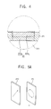
- FIG. 4 is an enlarged sectional view illustrating a second pattern in FIG. 3 .
- FIG. 5A and FIG. 5B are conceptual diagrams explaining light passing through an optical plate in FIG. 3 .
- FIG. 6A , FIG. 6B , FIG. 6C , and FIG. 6D are cross-sectional views explaining an exemplary embodiment of a method of manufacturing the optical plate in FIG. 1 .
- FIG. 7 is a cross-sectional view illustrating an optical plate according to another exemplary embodiment of the present invention.
- FIG. 8A and FIG. 8B are conceptual diagrams explaining light passing through the optical plate in FIG. 7 .
- FIG. 9 is a cross-sectional view explaining an exemplary embodiment of a method of manufacturing the optical plate in FIG. 7 .
- FIG. 10 is a cross-sectional view illustrating an optical plate according to still another exemplary embodiment of the present invention.
- FIG. 11 is a conceptual diagram explaining light passing through the optical plate in FIG. 10 .
- FIG. 12 is a cross-sectional view explaining an exemplary embodiment of a method of manufacturing the optical plate in FIG. 10 .
- FIG. 13 is a cross-sectional view explaining a method of manufacturing an optical plate according to another exemplary embodiment of the present invention.
- FIG. 14 and FIG. 15 are cross-sectional views explaining a method of manufacturing an optical plate according to still another exemplary embodiment of the present invention.
- FIG. 16 is a cross-sectional view explaining a display apparatus according to still another exemplary embodiment of the present invention.
- FIG. 17 is a cross-sectional view explaining an exemplary embodiment of a method of manufacturing the display apparatus in FIG. 16 .
- FIG. 18 is a cross-sectional view explaining a display apparatus according to still another exemplary embodiment of the present invention.
- FIG. 19 is a cross-sectional view explaining an exemplary embodiment of a method of manufacturing the display apparatus in FIG. 18 .
- FIG. 20 is a cross-sectional view explaining a method of manufacturing a display apparatus according to still another exemplary embodiment of the present invention.
- a display apparatus including an optical plate is explained referring to FIG. 1 , FIG. 2 and FIG. 3 , and the optical plate is specifically explained referring to FIG. 5A , FIG. 5B and FIG. 5C according to an exemplary embodiment of the present invention.
- FIG. 1 is a conceptual perspective view explaining a display apparatus according to an exemplary embodiment of the present invention.
- the display apparatus 500 includes a display panel 100 , a polarizing plate 200 , an optical plate 300 and a backlight assembly 400 .
- the display panel 100 displays an image using light provided from the backlight assembly 400 .
- the display panel 100 may be a liquid crystal display panel including a liquid crystal.
- the display panel 100 may be disposed over the backlight assembly 400 .
- the polarizing plate 200 is disposed between the display panel 100 and the backlight assembly 400 .
- the polarizing plate 200 polarizes incident light provided from the backlight assembly 400 to provide the display panel 100 with the light.
- the polarizing plate 200 transmits a first polarized light of the incident light.
- the optical plate 300 is disposed on the display panel 100 .
- the optical plate 300 includes a polarizing layer 310 and a phase delaying layer 320 .
- the polarizing layer 310 transmits a second polarized light of light passing through the display panel 100 .
- a polarization direction of the second polarized light is different from that of the first polarized light.
- the polarization direction of the second polarized light may be perpendicular to that of the first polarized light.
- the optical plate 300 and the display panel 100 are illustrated in FIG. 1 as separated from each other, the optical plate 300 may be directly attached to the display panel 100 , or may be directly formed on the display panel 100 .
- the polarizing layer 310 may be a constituent of the optical plate 300 and may be defined as “a layer”. Alternatively, the polarizing layer 310 may be an independent constituent of the display panel 100 and may be defined as “a plate”. In the present exemplary embodiment, “a polarizing layer” is substantially the same as the polarizing plate 200 having a latticed line pattern and formed on a base substrate. The polarizing layer is defined and used to distinguish from the polarizing plate 200 .
- the phase delaying layer 320 is disposed on the polarizing layer 310 and delays a phase of the second polarized light passing through the polarizing layer 310 .
- the phase delaying layer 320 includes a first pattern P 1 delaying a phase of the second polarized light by 3 ⁇ /4, and a second pattern P 2 delaying the phase of the second polarized light by ⁇ /4.
- ⁇ is a wavelength of light.
- the wavelength may be between about 500 nm to about 550 nm that may be a wavelength of green light.
- the first pattern P 1 and the second pattern P 2 extend along a first direction D 1 of the display apparatus 500 , and are repetitively arranged along a second direction D 2 .
- the second direction D 2 may be substantially perpendicular to the first direction D 1 .
- the first and second patterns P 1 and P 2 are arranged as a latticed line.
- the first pattern P 1 delays the phase of the second polarized light to transform the second polarized light to a first circular polarized light.
- the first pattern P 1 may transform the second polarized light to the first circular polarized light in a similar manner as rotating the second polarized light by ⁇ 45 degrees using a rotator.
- the second pattern P 2 delays the phase of the second polarized light to transform the second polarized light to a second circular polarized light different from the first pattern P 1 .
- the second pattern P 2 may transform the second polarized light to the second circular polarized light in a similar manner as rotating the second polarized light by +45 degrees using the rotator.
- Polarization directions of the first and second circular polarized lights are opposite to each other.
- the first circular polarized light may be a left circular polarized light
- the second circular polarized light may be a right circular polarized light.
- the first circular polarized light may be a right circular polarized light
- the second circular polarized light may be a left circular polarized light.
- the display apparatus 500 displays a 2-dimensional (2D) image, but an observer wearing polarizing spectacles 600 may receive the first circular polarized light to one eye and the second circular polarized light to the other eye respectively through the polarizing spectacles 600 .
- the polarizing spectacles 600 include a first spectacle part 610 passing the first circular polarized light and a second spectacle part 620 passing the second circular polarized light.
- the first circular polarized light may pass through the first spectacle part 610 , but may not pass through the second spectacle part 620 .
- the second circular polarized light may pass through the second spectacle part 620 , but may not pass through the first spectacle part 610 .
- the observer watches the first circular polarized light only through the first eye, and the second circular polarized light only through the second eye, and a brain of the observer perceives substantially a stereoscopic image, which means a 3-dimensional (3D) image.
- the brain of the observer may perceive a plan image, which means the 2D image, without wearing the polarizing spectacles 600 .
- FIG. 2 is an enlarged plan view illustrating an arrangement between a display panel 100 and a phase delaying layer 320 in FIG. 1 .
- FIG. 3 is a cross-sectional view taken along line I-I′ of FIG. 1 .
- the display panel 100 includes a first substrate 110 having a thin-film transistor (TFT, not shown) and a pixel electrode (not shown), and a second substrate 120 facing the first substrate 110 .
- a display element is disposed between the first substrate 110 and the second substrate 120 to control a transmissivity of light provided from the backlight assembly 400 , and the display panel 100 may display an image.
- the display element may be, for example, a liquid crystal.
- the polarizing plate 200 is combined with a light incident surface of the display panel 100 receiving light from the backlight assembly 400 .
- the optical plate 300 is combined with a light exiting surface facing the light incident surface.
- the polarizing plate 200 is combined with an external face of the first substrate 110 that is the light incident surface
- the optical plate 300 is combined with an external face of the second substrate 120 that is the light exiting surface.
- the polarizing layer 310 and the phase delaying layer 320 may be sequentially formed on the external surface of the second substrate 120 .
- the display panel 100 includes a plurality of pixel cells defined by combining the first substrate 110 and the second substrate 120 .
- Each of the pixel cells includes a pixel electrode and a color filter displaying a color.
- the color filter may be formed on the first substrate 110 , or formed on the second substrate 120 .
- the pixel cells may include a red (R) pixel, a green (G) pixel and a blue (B) pixel respectively emitting red light, green light and blue light.
- the R, G and B pixels are repetitively arranged along the first direction D 1 to define an n-th pixel line Rn.
- R, G and B pixels respectively arranged along the second direction D 2 of the R, G and B pixels define an (n+1)-th pixel line Rn+1 arranged along the second direction D 2 from the n-th pixel line Rn.
- An (n+2)-th pixel line Rn+2 is arranged along the second direction D 2 from the (n+1)-th pixel line Rn+1.
- a plurality of first patterns P 1 extends along the first direction D 1 and the first patterns P 1 are spaced apart from each other along the second direction D 2 , and thus the first patterns P 1 are disposed on the n-th and (n+2)-th pixel lines Rn and Rn+2.
- the second pattern P 2 is disposed between the adjacent first patterns P 1 , and thus the second pattern P 2 is disposed on the (n+1)-th pixel line Rn+1.
- a phase delaying axis of the phase delaying layer 320 has an inclination with respect to a polarized light absorbing axis of the polarizing layer 310 .
- the polarized light absorbing axis may extend along a third direction D 3 between the first direction D 1 and the second direction D 2 .
- the phase delaying axis has an inclination of 45 degrees with respect to the polarized light absorbing axis, so that the phase delaying layer circularly polarizes the second polarized light.
- FIG. 4 is an enlarged sectional view illustrating the second pattern P 2 in FIG. 3 .
- the second pattern P 2 may include a phase delaying portion 323 a and an isotropic optical portion 323 b .
- the phase delaying portion 323 a is optically anisotropic.
- the isotropic optical portion 323 b is isotropic and disposed on the phase delaying portion 323 a .
- the phase delaying portion 323 a delays the phase of the second polarized light by substantially ⁇ /4.
- the first pattern P 1 is partially transformed to the isotropic optical portion 323 b , and a portion of the first pattern P 1 which is not transformed to the isotropic optical portion 323 b remains as the phase delaying portion 323 a .
- the isotropic optical portion 323 b transmits light passing through the phase delaying portion 323 a without changing optical characteristics of the light.
- FIG. 5A and FIG. 5B are conceptual diagrams explaining light passing through the exemplary embodiment of an optical plate 300 shown in FIG. 3 .
- the first pattern P 1 is formed as a single layer delaying the phase of the second polarized light by 3 ⁇ /4.
- the phase delaying layer 320 includes a third pattern delaying the phase of the second polarized light by 3 ⁇ /4 and a fourth pattern delaying the phase of the second polarized light by ⁇ /4.
- the third and fourth patterns may be arranged as a checkerboard shape.
- each of the third pattern and the fourth pattern may be arranged as the checkerboard shape corresponding to at least one unit.
- FIG. 6A , FIG. 6B , FIG. 6C and FIG. 6D are cross-sectional views explaining an exemplary embodiment of a method of manufacturing the optical plate 300 illustrated in FIG. 1 .
- a first phase delaying film PL 1 is formed on the polarizing layer 310 .
- the first phase delaying film PL 1 is a phase delaying film delaying the phase of the second polarized light passing through the polarizing layer 310 by 3 ⁇ /4.
- a phase delaying axis of the first phase delaying film PL 1 is formed on the polarizing layer 310 , and has an inclination of 45 degrees with respect to the polarized light absorbing axis of the polarizing layer 310 .
- heat E is applied to a first portion 324 of the first phase delaying film PL 1 .
- a heat-transfer printer may be used for applying the heat E.
- the heat-transfer printer applies the heat E, and thus the first phase delaying film PL 1 is locally and partially heated to form the isotropic optical portion 323 b.
- the first phase delaying film PL 1 is locally and partially transformed to the isotropic optical portion 323 b , and thus a second portion 326 of the first phase delaying film PL 1 adjacent to the first portion 324 may be defined as the first pattern P 1 .
- the isotropic optical portion 323 b is formed of the first portion 324 , and thus a portion of the first phase delaying film PL 1 under the isotropic optical portion 323 b remains optically anisotropic, to be the phase delaying portion 323 a.
- the heat E is applied to a third portion of the first phase delaying film PL 1 spaced apart from the first portion 324 .
- the isotropic optical portion 323 b is formed on the third portion.
- a portion of the first phase delaying film PL 1 under the isotropic optical portion 323 b remains optically anisotropic, to be the phase delaying portion 323 a.
- the processes mentioned above are repeatedly performed, so that the phase delaying layer 320 including the first pattern P 1 and the second pattern P 2 may be formed from the first phase delaying film PL 1 . Accordingly, the optical plate 300 is completed.
- FIG. 6A , FIG. 6B , and FIG. 6C may be performed with a single step using the heat-transfer printer heating a plurality of portions of the first phase delaying film PL 1 at the same time.
- the phase delaying layer 320 that transmits the light delayed by the phases different from each other through a light exiting surface may be easily formed via a simple process. Accordingly, a productivity of the optical plate 300 may be enhanced.
- the display panel 100 having the first substrate 110 and the second substrate 120 is formed.
- the optical plate 300 illustrated in FIG. 6 D may be combined with the display panel 100 . Accordingly, a thickness of the display apparatus 500 may be decreased and the process of manufacturing the display apparatus 500 may be simplified using the optical plate 300 .
- FIG. 7 is a cross-sectional view illustrating an optical plate according to another exemplary embodiment of the present invention.
- the optical plate 301 includes the polarizing layer 310 and a phase delaying layer 321 formed on the polarizing layer 310 .
- the phase delaying layer 321 delays a phase of polarized light passing through the polarizing layer 310 , so that the polarized light is changed to first circular polarized light and second circular polarized light.
- the phase delaying layer 321 includes the first pattern P 1 delaying a phase of the polarized light by 3 ⁇ /4, and the second pattern P 2 delaying the phase of the polarized light by ⁇ /4.
- the first pattern P 1 includes a first optical layer 332 and a second optical layer 342 formed on the first optical layer 332 .
- a phase delaying axis of the first optical layer 332 may be substantially the same as that of the second optical layer 342 .
- the first optical layer 332 delays the phase of the light by ⁇ /4.
- the second optical layer 342 delays the phase of the light passing through the first optical layer 332 by ⁇ /2.
- the second pattern P 2 includes an anisotropic optical layer 334 that is substantially the same as the first optical layer 332 and an isotropic optical layer 344 formed on the anisotropic optical layer 334 .
- the anisotropic optical layer 334 delays the phase of the polarized light by ⁇ /4.
- the isotropic optical layer 344 transmits the polarized light delayed by ⁇ /4 without an optical change.
- the first optical layer 332 and the anisotropic optical layer 334 are substantially the same layer that delays the phase of the polarized light by ⁇ /4.
- a layer substantially the same as the second optical layer 342 is transformed by heat E, to be formed as the isotropic optical layer 344 .
- FIG. 8A and FIG. 8B are conceptual diagrams explaining the light passing through the exemplary embodiment of an optical plate 301 illustrated in FIG. 7 .
- incident light passes through the polarizing layer 310 , and becomes the polarized light.
- the polarized light passes through the first optical layer 332 of the first pattern P 1 , and thus the phase of the polarized light is delayed by ⁇ /4.
- the polarized light delayed by ⁇ /4 may be substantially the same as the second circular polarized light.
- the second circular polarized light passes through the second optical layer 342 of the first pattern P 1 , and thus the polarization direction of the second circular polarized light is changed to be the first circular polarized light.
- the polarized light sequentially passes through the first optical layer 332 and the second optical layer 342 to become the first circular polarized light as the polarized light passes through a 3 ⁇ /4 delaying plate.
- the incident light passes through the polarizing layer 310 , and becomes the polarized light.
- the polarized light passes through the anisotropic optical layer 334 .
- the phase of the polarized light is delayed by ⁇ /4 and becomes the second circular polarized light.
- the second circular polarized light passes through the isotropic optical layer 344 without an optical change. Since the isotropic optical layer 344 has no optical effect on the second circular polarized light, the second circular polarized light passes through the isotropic optical layer 344 .
- FIG. 9 is a cross-sectional view explaining an exemplary embodiment of a method of manufacturing the optical plate 301 illustrated in FIG. 7 .
- the polarizing layer 310 is formed.
- a process for forming the polarizing layer 310 is substantially the same as that described referring to FIG. 6A . Thus, any repetitive explanation concerning the above elements will be omitted.
- An anisotropic optical film having a first optical film 330 and a second optical film PL 2 is formed on the polarizing layer 310 .
- the first optical film 330 is a phase delaying film delaying the phase of the polarized light passing through the polarizing layer 310 by ⁇ /4.
- a phase delaying axis of the first optical film 330 is formed on the polarizing layer 310 , and has an inclination of 45 degrees with respect to the polarized light absorbing axis of the polarizing layer 310 .
- the second optical film PL 2 is a phase delaying film delaying the phase of the second circular polarized light transmitted by the first optical film 330 by ⁇ /2.
- a phase delaying axis of the second optical film PL 2 is formed on the polarizing layer 310 , and has an inclination of 45 degrees with respect to the polarized light absorbing axis of the polarizing layer 310 .
- the phase delaying axis of the second optical film PL 2 may be substantially the same as the phase delaying axis of the first optical film 330 .
- Heat E is applied to a first portion of the second optical film PL 2 .
- an optical characteristic of the second optical film PL 2 is changed, and the isotropic optical layer 344 is formed.
- the first optical film 330 disposed under the second optical film PL 2 is defined as the anisotropic optical layer 334 .
- the heat E is applied to a second portion of the second optical film PL 2 spaced apart from the first portion, and thus the isotropic optical layer 344 is formed.
- the processes mentioned above are performed repeatedly, so that the optical plate 301 illustrated in FIG. 7 may be formed.
- the phase delaying layer transmitting the light delayed by the phases different from each other through the light exiting surface may be easily and simply formed via the processes using two optical films different from each other. Accordingly, a productivity of the optical plate 301 manufacturing may be enhanced.
- the display apparatus may be manufactured by combining the optical plate 301 with the display panel 100 illustrated in FIG. 1 .
- the display panel 100 illustrated in FIG. 3 is manufactured and the polarizing plate 200 is combined with the external surface of the first substrate 110 of the display panel 100 , and then, the optical plate 301 illustrated in FIG. 7 may be combined with the display panel 100 . Accordingly, a thickness of the display apparatus 500 may be decreased and the process of manufacturing the display apparatus 500 may be simplified using the optical plate 301 .
- FIG. 10 is a cross-sectional view illustrating an optical plate according to still another exemplary embodiment of the present invention.
- an optical plate 302 includes the polarizing layer 310 , and a phase delaying layer 322 formed on the polarizing layer 310 .
- the phase delaying layer 322 delays a phase of a polarized light passing through the polarizing layer 310 , so that the polarized light is changed to a first circular polarized light and a second circular polarized light.
- the phase delaying layer 322 includes the first pattern P 1 delaying the phase of the polarized light by 3 ⁇ /4 and the second pattern P 2 delaying the phase of the polarized light by ⁇ /4.
- the first pattern P 1 includes the first optical layer 332 and the second optical layer 342 formed on the first optical layer 332 .
- the first pattern P 1 is substantially the same as the first pattern described referring to FIG. 7 .
- the second pattern P 2 includes only the anisotropic optical layer 334 that is substantially the same as the first optical layer 332 .
- the anisotropic optical layer 334 delays the phase of the polarized light by ⁇ /4.
- the first optical layer 332 and the anisotropic optical layer 334 are substantially the same as each other, both of which delay the phase of the polarized light by ⁇ /4.
- a process of transforming the polarized light into the first circular polarized light by the first pattern P 1 is substantially the same as that described referring to FIG. 8A . Thus, any repetitive explanation concerning the above elements will be omitted.
- FIG. 11 is a conceptual diagram explaining the light passing through the exemplary embodiment of an optical plate 302 illustrated in FIG. 10 .
- incident light passes through the polarizing layer 310 , and becomes the polarized light.
- the polarized light passes through the first pattern P 1 and the phase of the polarized light is delayed by ⁇ /4, and thus the polarized light becomes the second circular polarized light.
- the second pattern P 2 includes only the anisotropic optical layer 334 , the second circular polarized light passing through the anisotropic optical layer 334 is transferred to the observer without an optical change.
- FIG. 12 is a cross-sectional view explaining an exemplary embodiment of a method of manufacturing the optical plate 302 in FIG. 10 .
- the polarizing layer 310 is formed.
- a process for forming the polarizing layer 310 is substantially the same as that described referring to FIG. 6A . Thus, any repetitive explanation concerning the above elements will be omitted.
- a second phase delaying film having the first optical film 330 and the second optical film PL 2 is formed on the polarizing layer 310 .
- the first optical film 330 and the second optical film PL 2 are substantially the same as those described in FIG. 9 . Thus, any repetitive explanation concerning the above elements will be omitted.
- a photoresist pattern PR is formed on the second optical film PL 2 .
- the second optical film PL 2 is patterned using the photoresist pattern PR as a mask.
- a portion of the second optical film PL 2 in which the photoresist pattern PR is not formed is removed to be a separated portion 345 .
- the second optical film PL 2 under the photoresist pattern PR remains to be the second optical layer 342 .
- the phase delaying layer transmitting light delayed by the phases different from each other through the light exiting surface may be easily and simply formed by the processes using two optical films different from each other. Accordingly, the productivity of the optical plate 302 manufacturing may be enhanced.
- the display apparatus may be manufactured by combining the optical plate 302 with the display panel 100 illustrated in FIG. 1 .
- the display panel 100 illustrated in FIG. 3 is manufactured and the polarizing plate 200 is combined with the external surface of the first substrate 110 of the display panel 100 , and then the optical plate 302 illustrated in FIG. 10 may be combined with the display panel 100 . Accordingly, a thickness of the display apparatus 502 may be decreased and the process of manufacturing the display apparatus may be simplified using the optical plate 302 .
- FIG. 13 Another exemplary embodiment of a method of manufacturing the optical plate 302 illustrated in FIG. 10 is explained referring to FIG. 13 .
- FIG. 13 is a cross-sectional view explaining the method of manufacturing an optical plate according to still another exemplary embodiment of the present invention.
- the optical plate 302 according to the present exemplary embodiment is substantially the same as the optical plate 302 illustrated in FIG. 10 . Thus, any repetitive explanation concerning the above elements will be omitted.
- the polarizing layer 310 is formed, and a third phase delaying film having the first optical film 330 is formed on the polarizing layer 310 .
- the polarizing layer 310 and the first optical film 330 are substantially the same as those described referring to FIG. 9 . Thus, any repetitive explanation concerning the above elements will be omitted.
- An anisotropic optical pattern 346 delaying a phase of light passing through the first optical film 330 by ⁇ /2 and spaced apart from each other is formed on the first optical film 330 .
- An external pressure P is applied to the anisotropic optical pattern 346 , so that the anisotropic optical pattern 346 is attached on the first optical film 330 .
- An adhesive may be disposed between the anisotropic optical pattern 346 and the first optical film 330 .
- the phase delaying layer transmitting light delayed by the phases different from each other through the light exiting surface may be easily and simply formed by the processes using two optical films different from each other. Accordingly, the productivity of the optical plate 302 manufacturing may be enhanced.
- a display apparatus accordingly to the present exemplary embodiment is substantially the same as the display apparatus 500 described referring to FIG. 2 and FIG. 3 . Thus, any repetitive explanation concerning the above elements will be omitted.
- the display apparatus 500 according to the present exemplary embodiment is explained referring to FIG. 2 and FIG. 3 .
- the display apparatus 500 according to the present exemplary embodiment includes the display panel 100 having the first substrate 110 and the second substrate 120 , the polarizing plate 200 , the optical plate 300 and the backlight assembly 400 .
- FIG. 14 and FIG. 15 are cross-sectional views explaining a method of manufacturing the optical plate according to still another exemplary embodiment of the present invention.
- the display panel 100 having the first substrate 110 and the second substrate 120 is formed, and the polarizing plate 200 is combined with the external surface of the first substrate 110 of the display panel 100 . Then, the polarizing layer 310 is formed on the external surface of the second substrate 120 . The polarizing layer 310 is formed on the second substrate 120 using the second substrate 120 as a base substrate.
- the first phase delaying film PL 1 is formed on the polarizing layer 310 .
- the first phase delaying film PL 1 is the phase delaying film delaying the phase of the second polarized light passing through the polarizing layer 310 by 3 ⁇ /4.
- the phase delaying axis of the first phase delaying film PL 1 is formed on the polarizing layer 310 , and has an inclination of 45 degrees with respect to the polarized light absorbing axis of the polarizing layer 310 .
- Heat E is applied to a portion of the first phase delaying film PL 1 that corresponds to the (n+1)-th pixel line Rn+1.
- the heat-transfer printer may be used in the course of applying the heat E.
- the heat-transfer printer locally applies the heat E to the portion of the first phase delaying film PL 1 corresponding to the (n+1)-th pixel line Rn+1, and thus the first phase delaying film PL 1 is locally and partially heated to form the isotropic optical portion 323 b.
- the first phase delaying film PL 1 corresponding to the (n+1)-th pixel line Rn+1 is locally and partially transformed to the isotropic optical portion 323 b , and thus a portion of the first phase delaying film PL 1 that corresponds to the n-th pixel line Rn may be defined as the first pattern P 1 .
- the isotropic optical portion 323 b is formed on the portion of the first phase delaying film PL 1 corresponding to the (n+1)-th pixel line Rn+1, and thus the portion of the first phase delaying film PL 1 under the isotropic optical portion 323 b remains optically anisotropic, to be the phase delaying portion 323 a.
- the heat E is applied to a portion of the first phase delaying film PL 1 that corresponds to an (n+3)-th pixel line Rn+3.
- the heat-transfer printer locally applies the heat E to the portion of the first phase delaying film PL 1 corresponding to the (n+3)-th pixel line Rn+3, and thus the first phase delaying film PL 1 is locally and partially heated to form the isotropic optical portion 323 b .
- the first phase delaying film PL 1 corresponding to the (n+3)-th pixel line Rn+3 is locally and partially transformed to the isotropic optical portion 323 b , and thus a portion of the first phase delaying film PL 1 that corresponds to the (n+2)-th pixel line Rn+2 may be defined as the first pattern P 1 .
- the isotropic optical portion 323 b is formed on the portion of the first phase delaying film PL 1 corresponding to the (n+3)-th pixel line Rn+3, and thus the portion of the first phase delaying film PL 1 under the isotropic optical portion 323 b corresponding to the (n+3)-th pixel line Rn+3 remains optically anisotropic, to be the phase delaying portion 323 a.
- the processes mentioned above are performed, so that the phase delaying layer 320 may be formed from the first phase delaying film PL 1 . Accordingly, the optical plate 300 may be formed on the second substrate 120 .
- the processes in FIG. 14 and FIG. 15 may be performed with a single step using the heat-transfer printer heating the (n+1)-th and (n+3)-th pixel lines Rn+1 and Rn+3 at the same time.
- the optical plate 300 having the phase delaying layer 320 that is integrally formed with the polarizing layer 310 is directly formed on the display panel 100 , and thus a reliability of an alignment between the display panel 100 and the optical plate 300 may be enhanced.
- a thickness of the display apparatus 500 may be decreased and the process of manufacturing the display apparatus 500 may be simplified using the optical plate 300 .
- FIG. 16 is a cross-sectional view explaining a display apparatus according to still another exemplary embodiment of the present invention.
- the display apparatus 501 includes the display panel 100 having the first substrate 110 and the second substrate 120 , the polarizing plate 200 , the optical plate 301 and the backlight assembly 400 .
- the display apparatus 501 illustrated in FIG. 16 is substantially the same as the display apparatus 500 illustrated in FIG. 2 and FIG. 3 except for the optical plate 301 .
- the optical plate 301 according to the present exemplary embodiment is substantially the same as the optical plate 301 illustrated in FIG. 7 except that the optical plate 301 is directly formed on the second substrate 120 .
- any repetitive explanation concerning the above elements will be omitted.
- the optical plate 301 includes the polarizing layer 310 formed on the second substrate 120 of the display panel 100 and the phase delaying layer 321 formed on the polarizing layer 310 .
- the phase delaying layer 321 includes the first pattern P 1 delaying the phase of the second polarized light by 3 ⁇ /4 and the second pattern P 2 delaying the phase of the second polarized light by ⁇ /4.
- the first pattern P 1 is formed on the n-th and (n+2)-th pixel lines Rn and Rn+2, and the second pattern P 2 is formed on the (n+1)-th and (n+3)-th pixel lines Rn+1 and Rn+3.
- FIG. 17 is a cross-sectional view explaining a method of manufacturing the display apparatus in FIG. 16 .
- the display panel 100 having the first substrate 110 and the second substrate 120 is manufactured, and the polarizing plate 200 is combined with the external surface of the first substrate 110 of the display panel 100 . Then, the polarizing layer 310 is formed on the second substrate 120 using the second substrate 120 as the base substrate.
- the second anisotropic optical film having the first optical film 330 and the second optical film PL 2 is formed on the polarizing layer 310 .
- the second optical film PL 2 is substantially the same as that explained referring to FIG. 9 . Thus, any repetitive explanation concerning the above elements will be omitted.
- the heat E is applied to a portion of the second phase delaying film PL 2 that corresponds to the (n+1)-th pixel line Rn+1. Accordingly, the second phase delaying film PL 2 corresponding to the (n+1)-th pixel line Rn+1 is locally and partially transformed to the isotropic optical layer 344 .
- the isotropic optical layer 344 is formed on the portion of the second phase delaying film PL 2 corresponding to the (n+1)-th pixel line Rn+1, and thus a portion of the second phase delaying film PL 2 that corresponds to the n-th pixel line Rn may be defined as the second optical layer 342 .
- the heat E is applied to a portion of the second phase delaying film PL 2 that corresponds to the (n+3)-th pixel line Rn+3.
- the processes mentioned above are performed, so that the phase delaying layer 321 may be formed from the first optical film 330 and the second optical film PL 2 . Accordingly, the optical plate 301 may be formed on the second substrate 120 .
- the optical plate 301 having the phase delaying layer 321 that is integrally formed with the polarizing layer 310 is directly formed on the display panel 100 , and thus a reliability of an alignment between the display panel 100 and the optical plate 301 may be enhanced.
- a thickness of the display apparatus 501 may be decreased and the process of manufacturing the display apparatus 501 may be simplified using the optical plate 301 .
- FIG. 18 is a cross-sectional view explaining a display apparatus according to still another exemplary embodiment of the present invention.
- the display apparatus 502 includes the display panel 100 having the first substrate 110 and the second substrate 120 , the polarizing plate 200 , the optical plate 302 and the backlight assembly 400 .
- the display apparatus 502 illustrated in FIG. 18 is substantially the same as the display apparatus 501 illustrated in FIG. 16 except for the optical plate 302 .
- the optical plate 302 is substantially the same as the optical plate 302 illustrated in FIG. 10 except that the optical plate 302 is directly formed on the second substrate 120 .
- any repetitive explanation concerning the above elements will be omitted.
- FIG. 19 is a cross-sectional view explaining a method of manufacturing the display apparatus in FIG. 18 .
- the display panel 100 having the first substrate 110 and the second substrate 120 is formed, and the polarizing plate 200 is combined with the external surface of the first substrate 110 of the display panel 100 . Then, the polarizing layer 310 is formed on the external surface of the second substrate 120 . The polarizing layer 310 is formed on the second substrate 120 using the second substrate 120 as a base substrate.
- the second phase delaying film having the first optical film 330 and the second optical film PL 2 is formed on the polarizing layer 310 .
- the anisotropic optical film according to the present exemplary embodiment is substantially the same as that illustrated in FIG. 9 . Thus, any repetitive explanation concerning the above elements will be omitted.
- the photoresist pattern PR is formed on the second optical film PL 2 , and the second optical film PL 2 is patterned using the photoresist pattern PR as a mask.
- a portion of the second optical film PL 2 that corresponds to the (n+1)-th and (n+3)-th pixel lines Rn+1 and Rn+3 of the display panel 100 is removed to be a separated portion 345 .
- a portion of the second optical film PL 2 that corresponds to the n-th and (n+2)-th pixel lines Rn and Rn+2 remains to be the second optical layer 342 .
- a reliability of an alignment between the display panel 100 and the optical plate 302 may be enhanced.
- the optical plate 302 may be easily and simply formed via the above-mentioned processes.
- a thickness of the display apparatus 502 may be decreased and the process of manufacturing the display apparatus 502 may be simplified using the optical plate 302 .
- FIG. 20 Another exemplary method of manufacturing the display apparatus 502 illustrated in FIG. 18 , which is different from the method explained in FIG. 19 , is explained referring to FIG. 20 .
- FIG. 20 is a cross-sectional view explaining a method of manufacturing the display apparatus according to still another exemplary embodiment of the present invention.
- a display apparatus according to the present exemplary embodiment referring to FIG. 18 is substantially the same as the display apparatus illustrated in FIG. 18 . Thus, any repetitive explanation concerning the above elements will be omitted.
- the display panel 100 having the first substrate 110 and the second substrate 120 is manufactured, and the polarizing plate 200 is combined with the external surface of the first substrate 110 of the display panel 100 . Then, the polarizing layer 310 is formed on the external surface of the second substrate 120 . The polarizing layer 310 is formed on the second substrate 120 using the second substrate 120 as a base substrate. The third phase delaying film having the first optical film 330 is formed on the polarizing layer 310 .
- the first optical film 330 according to the present example embodiment is substantially the same as that explained referring to FIG. 9 . Thus, any repetitive explanation concerning the above elements will be omitted.
- the anisotropic optical pattern 346 delaying the phase of the light passing through the first optical film 330 by ⁇ /2 and spaced apart from each other is formed on the first optical film 330 .
- the anisotropic optical pattern 346 may be formed only on portions of the display panel 100 corresponding to the n-th and (n+2)-th pixel lines Rn and Rn+2. A portion of the first optical film 330 corresponding to (n+1)-th and (n+3)-th pixel lines Rn+1 and Rn+3 is exposed by the anisotropic optical pattern 346 .
- the external pressure P is applied to the anisotropic optical pattern 346 and thus the anisotropic optical pattern 346 is attached on the first optical film 330 .
- the adhesive may be formed between the anisotropic optical pattern 346 and the first optical film 330 .
- the optical plate, the method of manufacturing the optical plate, the display apparatus, and the method of manufacturing the display apparatus according to the present invention may be applied to not only a liquid crystal display (LCD), but also a portable display apparatus, a plasma display panel (PDP), a flat display apparatus, a 3D game image apparatus, a 3D television for broadcasting, a 3D display for military affairs, a 3D display for simulated training and a 3D display for medical industries.
- LCD liquid crystal display
- PDP plasma display panel
- the optical plate having the polarizing layer and the phase delaying layer may be used to increase a reliability of aligning the display panel with the optical plate.
- a thickness of the display apparatus may be decreased, and a process of the manufacturing of the display apparatus may be simplified.
Landscapes
- Physics & Mathematics (AREA)
- General Physics & Mathematics (AREA)
- Optics & Photonics (AREA)
- Nonlinear Science (AREA)
- Mathematical Physics (AREA)
- Chemical & Material Sciences (AREA)
- Crystallography & Structural Chemistry (AREA)
- Liquid Crystal (AREA)
- Polarising Elements (AREA)
- Devices For Indicating Variable Information By Combining Individual Elements (AREA)
Abstract
Description
Claims (20)
Applications Claiming Priority (2)
| Application Number | Priority Date | Filing Date | Title |
|---|---|---|---|
| KR10-2010-0070820 | 2010-07-22 | ||
| KR1020100070820A KR101772505B1 (en) | 2010-07-22 | 2010-07-22 | Optical plate, method of manufacturing the optical plate. display device and method of manufacturing the display device |
Publications (2)
| Publication Number | Publication Date |
|---|---|
| US20120019745A1 US20120019745A1 (en) | 2012-01-26 |
| US8937697B2 true US8937697B2 (en) | 2015-01-20 |
Family
ID=45493328
Family Applications (1)
| Application Number | Title | Priority Date | Filing Date |
|---|---|---|---|
| US13/166,514 Active 2032-10-09 US8937697B2 (en) | 2010-07-22 | 2011-06-22 | Optical plate, method of manufacturing the optical plate, display apparatus, and method of manufacturing the display apparatus |
Country Status (4)
| Country | Link |
|---|---|
| US (1) | US8937697B2 (en) |
| JP (1) | JP5881328B2 (en) |
| KR (1) | KR101772505B1 (en) |
| CN (1) | CN102346312B (en) |
Families Citing this family (6)
| Publication number | Priority date | Publication date | Assignee | Title |
|---|---|---|---|---|
| KR101436806B1 (en) * | 2012-03-08 | 2014-09-03 | 엘지디스플레이 주식회사 | Display apparatus and method for manufacturing the same |
| WO2013165013A1 (en) * | 2012-05-02 | 2013-11-07 | 住友化学株式会社 | System for producing and method for manufacturing optical display device |
| JP2014164000A (en) * | 2013-02-21 | 2014-09-08 | Nitto Denko Corp | Method for cutting patterned optical film and system for controlling traveling of optical film |
| US10541556B2 (en) * | 2017-04-27 | 2020-01-21 | Honeywell International Inc. | System and approach to integrate and manage diverse demand response specifications for multi-site enterprises |
| JP2019184827A (en) * | 2018-04-10 | 2019-10-24 | シャープ株式会社 | Liquid crystal display and method for manufacturing the same |
| CN112014989A (en) * | 2019-05-31 | 2020-12-01 | 北京小米移动软件有限公司 | Display module, display device, display device control method and storage medium |
Citations (8)
| Publication number | Priority date | Publication date | Assignee | Title |
|---|---|---|---|---|
| US20020085280A1 (en) * | 2000-12-30 | 2002-07-04 | Jung Jin Hee | Polarized stereoscopic display apparatus and manufacturing method thereof |
| JP2004279946A (en) | 2003-03-18 | 2004-10-07 | Sharp Corp | 2D / 3D switching type liquid crystal display panel and 2D / 3D switching type liquid crystal display device |
| US20050146659A1 (en) * | 2004-01-05 | 2005-07-07 | Nec Lcd Technologies, Ltd | Liquid crystal display device |
| KR20070006116A (en) | 2005-07-07 | 2007-01-11 | 삼성전자주식회사 | Full parallax stereoscopic image display device for 2D / 3D image compatibility |
| CN101183177A (en) | 2007-12-13 | 2008-05-21 | 友达光电股份有限公司 | Stereoscopic display and manufacturing method thereof |
| TW200925653A (en) | 2007-12-03 | 2009-06-16 | Au Optronics Corp | Three-dimensional display device and fabricating method thereof |
| US20100073601A1 (en) | 2005-09-29 | 2010-03-25 | Casio Computer Co., Ltd. | Liquid crystal display apparatus capable of limiting view angle |
| US20110216277A1 (en) * | 2010-03-08 | 2011-09-08 | Au Optronics Corporation | Three-dimensional display and display method thereof |
Family Cites Families (10)
| Publication number | Priority date | Publication date | Assignee | Title |
|---|---|---|---|---|
| US5113285A (en) * | 1990-09-28 | 1992-05-12 | Honeywell Inc. | Full color three-dimensional flat panel display |
| EP0525473B1 (en) * | 1991-07-26 | 1998-05-06 | Rolic AG | Liquid crystal cell |
| JPH08334618A (en) * | 1995-06-02 | 1996-12-17 | Nitto Denko Corp | Retardation film, manufacturing method thereof, and laminated polarizing plate |
| JP3463846B2 (en) * | 1997-02-14 | 2003-11-05 | シャープ株式会社 | Polarizing element, method of manufacturing the same, and image display device |
| TW473654B (en) * | 1999-12-24 | 2002-01-21 | Ind Tech Res Inst | Micro-retarder |
| JP2005037736A (en) * | 2003-07-16 | 2005-02-10 | Sony Chem Corp | Optical element and method for manufacturing same |
| GB2437553A (en) * | 2006-04-28 | 2007-10-31 | Sharp Kk | Optical system with two spaced apart partial reflectors for display |
| JP2008170557A (en) * | 2007-01-09 | 2008-07-24 | Arisawa Mfg Co Ltd | Polarized glasses and stereoscopic image display system |
| JP5213843B2 (en) * | 2009-12-25 | 2013-06-19 | 日東電工株式会社 | Three-dimensional image display phase difference plate, polarizing element, manufacturing method thereof, and three-dimensional image display device |
| WO2012008750A2 (en) * | 2010-07-13 | 2012-01-19 | (주)Lg화학 | Polarizing eyeglasses |
-
2010
- 2010-07-22 KR KR1020100070820A patent/KR101772505B1/en active Active
-
2011
- 2011-06-22 US US13/166,514 patent/US8937697B2/en active Active
- 2011-07-22 CN CN201110216414.4A patent/CN102346312B/en active Active
- 2011-07-22 JP JP2011161043A patent/JP5881328B2/en active Active
Patent Citations (10)
| Publication number | Priority date | Publication date | Assignee | Title |
|---|---|---|---|---|
| US20020085280A1 (en) * | 2000-12-30 | 2002-07-04 | Jung Jin Hee | Polarized stereoscopic display apparatus and manufacturing method thereof |
| KR20020059028A (en) | 2000-12-30 | 2002-07-12 | 구본준, 론 위라하디락사 | Polarizing Stereoscopic Apparatus and Fabricating method thereof |
| JP2004279946A (en) | 2003-03-18 | 2004-10-07 | Sharp Corp | 2D / 3D switching type liquid crystal display panel and 2D / 3D switching type liquid crystal display device |
| US20050146659A1 (en) * | 2004-01-05 | 2005-07-07 | Nec Lcd Technologies, Ltd | Liquid crystal display device |
| CN100373236C (en) | 2004-01-05 | 2008-03-05 | Nec液晶技术株式会社 | Liquid crystal display device |
| KR20070006116A (en) | 2005-07-07 | 2007-01-11 | 삼성전자주식회사 | Full parallax stereoscopic image display device for 2D / 3D image compatibility |
| US20100073601A1 (en) | 2005-09-29 | 2010-03-25 | Casio Computer Co., Ltd. | Liquid crystal display apparatus capable of limiting view angle |
| TW200925653A (en) | 2007-12-03 | 2009-06-16 | Au Optronics Corp | Three-dimensional display device and fabricating method thereof |
| CN101183177A (en) | 2007-12-13 | 2008-05-21 | 友达光电股份有限公司 | Stereoscopic display and manufacturing method thereof |
| US20110216277A1 (en) * | 2010-03-08 | 2011-09-08 | Au Optronics Corporation | Three-dimensional display and display method thereof |
Also Published As
| Publication number | Publication date |
|---|---|
| JP5881328B2 (en) | 2016-03-09 |
| KR101772505B1 (en) | 2017-08-30 |
| CN102346312B (en) | 2015-09-09 |
| US20120019745A1 (en) | 2012-01-26 |
| JP2012027472A (en) | 2012-02-09 |
| KR20120009871A (en) | 2012-02-02 |
| CN102346312A (en) | 2012-02-08 |
Similar Documents
| Publication | Publication Date | Title |
|---|---|---|
| US8427529B2 (en) | Three-dimensional display, fabricating method and controlling method thereof | |
| JP3461680B2 (en) | Method for manufacturing optical element and image display device | |
| TWI381191B (en) | Three-dimensional display device and fabricating method thereof | |
| US8941787B2 (en) | Three-dimensional image display device and driving method thereof | |
| US20100238546A1 (en) | Three-dimensional display apparatus | |
| US8937697B2 (en) | Optical plate, method of manufacturing the optical plate, display apparatus, and method of manufacturing the display apparatus | |
| JP5914713B2 (en) | 3D stereoscopic glasses for stereoscopic video display device and stereoscopic video display device including the same | |
| US20130107146A1 (en) | Display apparatus | |
| CN102193248A (en) | Stereoscopic display and display method thereof | |
| US20120105779A1 (en) | Color filter substrate, method of manufacturing thereof and 3d liquid crystal display | |
| JP3533057B2 (en) | Liquid crystal display | |
| US9019438B2 (en) | Polarization system and three-dimensional image display apparatus having the same | |
| TWI424230B (en) | Stereoscopic display device and manufacturing method thereof | |
| US8456580B2 (en) | Three-dimensional display and displaying method thereof | |
| US20130010359A1 (en) | Polarization system and three dimensional image display apparatus having the same | |
| US20130063685A1 (en) | 3d display panel and method for manufacturing the same | |
| JP2010079216A (en) | Stereoscopic image display | |
| KR101849177B1 (en) | 3 dimensional stereography image display device and method of fabricationg the same | |
| KR101702078B1 (en) | 3 dimensional stereography image displayable system | |
| KR101974961B1 (en) | 3D image display device and driving method for the same | |
| KR101949388B1 (en) | 3 dimensional stereography image display device | |
| KR101886304B1 (en) | image display device and manufacturing method of the same |
Legal Events
| Date | Code | Title | Description |
|---|---|---|---|
| AS | Assignment |
Owner name: SAMSUNG ELECTRONICS CO., LTD., KOREA, REPUBLIC OF Free format text: ASSIGNMENT OF ASSIGNORS INTEREST;ASSIGNORS:DO, HEE-WOOK;SUH, DUCK-JONG;KIM, KYEONG HYEON;AND OTHERS;REEL/FRAME:026487/0411 Effective date: 20101029 |
|
| AS | Assignment |
Owner name: SAMSUNG DISPLAY CO., LTD., KOREA, REPUBLIC OF Free format text: CHANGE OF NAME;ASSIGNOR:SAMSUNG ELECTRONICS CO., LTD.;REEL/FRAME:028859/0868 Effective date: 20120403 |
|
| STCF | Information on status: patent grant |
Free format text: PATENTED CASE |
|
| MAFP | Maintenance fee payment |
Free format text: PAYMENT OF MAINTENANCE FEE, 4TH YEAR, LARGE ENTITY (ORIGINAL EVENT CODE: M1551) Year of fee payment: 4 |
|
| MAFP | Maintenance fee payment |
Free format text: PAYMENT OF MAINTENANCE FEE, 8TH YEAR, LARGE ENTITY (ORIGINAL EVENT CODE: M1552); ENTITY STATUS OF PATENT OWNER: LARGE ENTITY Year of fee payment: 8 |