US8937628B2 - Mapping of a contour shape to an X and Y coordinate system - Google Patents
Mapping of a contour shape to an X and Y coordinate system Download PDFInfo
- Publication number
- US8937628B2 US8937628B2 US13/494,065 US201213494065A US8937628B2 US 8937628 B2 US8937628 B2 US 8937628B2 US 201213494065 A US201213494065 A US 201213494065A US 8937628 B2 US8937628 B2 US 8937628B2
- Authority
- US
- United States
- Prior art keywords
- feature
- scale
- points
- image
- template
- Prior art date
- Legal status (The legal status is an assumption and is not a legal conclusion. Google has not performed a legal analysis and makes no representation as to the accuracy of the status listed.)
- Expired - Fee Related, expires
Links
Images


Classifications
-
- G06F17/50—
-
- G—PHYSICS
- G01—MEASURING; TESTING
- G01C—MEASURING DISTANCES, LEVELS OR BEARINGS; SURVEYING; NAVIGATION; GYROSCOPIC INSTRUMENTS; PHOTOGRAMMETRY OR VIDEOGRAMMETRY
- G01C11/00—Photogrammetry or videogrammetry, e.g. stereogrammetry; Photographic surveying
-
- G—PHYSICS
- G06—COMPUTING OR CALCULATING; COUNTING
- G06F—ELECTRIC DIGITAL DATA PROCESSING
- G06F3/00—Input arrangements for transferring data to be processed into a form capable of being handled by the computer; Output arrangements for transferring data from processing unit to output unit, e.g. interface arrangements
- G06F3/01—Input arrangements or combined input and output arrangements for interaction between user and computer
- G06F3/03—Arrangements for converting the position or the displacement of a member into a coded form
- G06F3/041—Digitisers, e.g. for touch screens or touch pads, characterised by the transducing means
- G06F3/042—Digitisers, e.g. for touch screens or touch pads, characterised by the transducing means by opto-electronic means
- G06F3/0425—Digitisers, e.g. for touch screens or touch pads, characterised by the transducing means by opto-electronic means using a single imaging device like a video camera for tracking the absolute position of a single or a plurality of objects with respect to an imaged reference surface, e.g. video camera imaging a display or a projection screen, a table or a wall surface, on which a computer generated image is displayed or projected
-
- G—PHYSICS
- G06—COMPUTING OR CALCULATING; COUNTING
- G06F—ELECTRIC DIGITAL DATA PROCESSING
- G06F30/00—Computer-aided design [CAD]
-
- G—PHYSICS
- G06—COMPUTING OR CALCULATING; COUNTING
- G06T—IMAGE DATA PROCESSING OR GENERATION, IN GENERAL
- G06T11/00—Two-dimensional [2D] image generation
-
- G06T11/003—
-
- G—PHYSICS
- G06—COMPUTING OR CALCULATING; COUNTING
- G06T—IMAGE DATA PROCESSING OR GENERATION, IN GENERAL
- G06T12/00—Tomographic reconstruction from projections
-
- G—PHYSICS
- G06—COMPUTING OR CALCULATING; COUNTING
- G06T—IMAGE DATA PROCESSING OR GENERATION, IN GENERAL
- G06T7/00—Image analysis
-
- G06T7/0042—
-
- G—PHYSICS
- G06—COMPUTING OR CALCULATING; COUNTING
- G06T—IMAGE DATA PROCESSING OR GENERATION, IN GENERAL
- G06T7/00—Image analysis
- G06T7/60—Analysis of geometric attributes
-
- G—PHYSICS
- G06—COMPUTING OR CALCULATING; COUNTING
- G06T—IMAGE DATA PROCESSING OR GENERATION, IN GENERAL
- G06T7/00—Image analysis
- G06T7/70—Determining position or orientation of objects or cameras
- G06T7/73—Determining position or orientation of objects or cameras using feature-based methods
-
- G06F17/5095—
-
- G—PHYSICS
- G06—COMPUTING OR CALCULATING; COUNTING
- G06F—ELECTRIC DIGITAL DATA PROCESSING
- G06F30/00—Computer-aided design [CAD]
- G06F30/10—Geometric CAD
- G06F30/15—Vehicle, aircraft or watercraft design
-
- G—PHYSICS
- G06—COMPUTING OR CALCULATING; COUNTING
- G06T—IMAGE DATA PROCESSING OR GENERATION, IN GENERAL
- G06T2207/00—Indexing scheme for image analysis or image enhancement
- G06T2207/10—Image acquisition modality
- G06T2207/10004—Still image; Photographic image
-
- G—PHYSICS
- G06—COMPUTING OR CALCULATING; COUNTING
- G06T—IMAGE DATA PROCESSING OR GENERATION, IN GENERAL
- G06T2207/00—Indexing scheme for image analysis or image enhancement
- G06T2207/30—Subject of image; Context of image processing
- G06T2207/30108—Industrial image inspection
- G06T2207/30164—Workpiece; Machine component
-
- G—PHYSICS
- G06—COMPUTING OR CALCULATING; COUNTING
- G06T—IMAGE DATA PROCESSING OR GENERATION, IN GENERAL
- G06T2207/00—Indexing scheme for image analysis or image enhancement
- G06T2207/30—Subject of image; Context of image processing
- G06T2207/30204—Marker
- G06T2207/30208—Marker matrix
Definitions
- the combustion chamber comprises a ring of fuel injectors that direct fuel (typically kerosene, jet fuel, propane or natural gas) into the compressed air stream to ignite the air/fuel mixture. Ignition increases both the temperature and pressure of the air/fuel mixture (also referred to as a working gas).
- fuel typically kerosene, jet fuel, propane or natural gas
- Ignition increases both the temperature and pressure of the air/fuel mixture (also referred to as a working gas).
- the working gas expands as it passes through the turbine.
- the turbine includes rows of stationary guide vanes and rotating turbine blades connected to a turbine shaft.
- the expanding gas flow is accelerated by the guide vanes and also directed over the rotating turbine blades, causing the blades and the turbine shaft to spin.
- the spinning shaft both turns the compressor and provides a mechanical output.
- Energy can be extracted from the turbine in the form of shaft power, compressed air, thrust or any combination of these, for use in powering aircraft, trains, ships and electric generators.
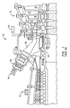
- FIG. 6 represents a photographic image of a template and marker board according to an embodiment of the present invention.
- feature is used herein to include any identifiable or distinguishable geometric element associated with an object or in a scene, and that can be seen in a photograph, such as but not limited to, an edge, portion, section, flaw, crack, line, joint, area, region, diameter, perimeter, circumference, boundary, contour, etc. Such features can be marked and measured.
- FIG. 1 illustrates a cross section of a combustion turbine 10 , including a compressor 12 , at least one combustor 14 , and a turbine section 16 .
- a plurality of combustors 14 is disposed in a circular arc around the turbine shaft.
- the turbine section 16 includes a plurality of rotating blades 18 secured to a rotatable central shaft 20 .
- a plurality of stationary vanes 22 is positioned upstream of the rotating blades 18 , and are secured to a turbine cylinder wall surfaces 23 .
- the vanes 22 are dimensioned and configured to guide the working gas over the rotating blades 18 .
- the contour (i.e., perimeter) of the lower and upper edge of each strut shield is accurately determined and recorded.
- the contour shapes are also referred to as target shapes herein. Accurate determination of the shape is particularly useful when replacing a strut shield as a maintenance item for operational engine.
- a pen, pencil or marker can be used as the scribing instrument. Any instrument that etches the coating on the material sheet or leaves a mark on the material sheet or on a coating of the material sheet is satisfactory. It is only necessary for the target shape (or a plurality of points that represent the target shape) to be visible in a subsequently exposed photograph.
- each marker 168 and the codes below each marker 168 uniquely identify the marker.
- Other marker boards that offer the same properties, i.e., control point locations with known X-Y coordinates and dimensions, can be used in lieu of the marker board 160 .
- a marker board having at least three control point locations is required.
- additional control point locations provide additional accuracy.
- the illustrated marker board 160 with its regular grid is a simple exemplary marker board that satisfies these requirements.
- a photograph of the target shape line 164 and the marker board 160 is taken. If necessary, more than one photograph can be taken and the photographs registered to show the entire target shape and a portion of the marker board 160 .
- the captured regions may be overlapped to simplify registering the individual images to form a complete photograph of the target shape. It is not necessary, however, to overlap the images if the images can be properly registered to illustrate the target shape, i.e., if the registration can be accomplished using the markers 168 . However, it is important that the entire target shape line 164 that is being modeled (measured) is visible when all the images are used to form the complete target shape.
- a method referred to as reconstruction is used to determine geometric properties of the target shape line 164 from the photographic image, specifically the geometric properties of feature points on the target shape line 164 . See a step 109 of FIG. 5 .
- reconstruction involves the creation of a metric (i.e., a known scale of the image) of a two or three dimensional representation of an object from the image or images of that object. For example, a distance between two points (i.e., two feature points) that lie on a plane parallel to the photographic image plane of the camera (thereby avoiding the calculation complexities and potential measurement errors associated with converting a two dimensional image to a three dimensional model) can be determined by measuring that distance on the image if the scale of the image is known. Note that the scale along an X axis may differ from the scale along a Y axis; both can be determined according to the present invention. The actual distance between the two feature points is then determined by multiplying the distance measured in the image by the reciprocal of the scale.
- a metric i.e., a known scale of the image
- Some segments of the target shape may not be captured with a sufficient number of feature points to adequately and accurately capture an important target shape feature.
- the scribed line representing the template of the target shape captured at the step 102 may not be sufficiently visible along some segments to accurately place an adequate number of feature points along that segment.
- the reconstruction software can automatically determine one or more intermediate feature points between two existing feature points, where the two existing feature points are not sufficiently closely spaced to capture an accurate target shape curve segment. Placement of these intermediate points is set forth in step 112 of FIG. 5 .
- An object incorporating the target shape is fabricated by transferring the CAD model to a CNC machine (i.e., a computerized numerically controlled machine) at a step 120 .
- a CNC machine i.e., a computerized numerically controlled machine
Landscapes
- Engineering & Computer Science (AREA)
- Physics & Mathematics (AREA)
- Theoretical Computer Science (AREA)
- General Physics & Mathematics (AREA)
- General Engineering & Computer Science (AREA)
- Computer Vision & Pattern Recognition (AREA)
- Geometry (AREA)
- Multimedia (AREA)
- Radar, Positioning & Navigation (AREA)
- Remote Sensing (AREA)
- Computer Hardware Design (AREA)
- Evolutionary Computation (AREA)
- Human Computer Interaction (AREA)
- Mathematical Analysis (AREA)
- Aviation & Aerospace Engineering (AREA)
- Computational Mathematics (AREA)
- Automation & Control Theory (AREA)
- Mathematical Optimization (AREA)
- Pure & Applied Mathematics (AREA)
- Length Measuring Devices By Optical Means (AREA)
- Architecture (AREA)
- Software Systems (AREA)
- Image Analysis (AREA)
- Image Processing (AREA)
Abstract
Description
Claims (17)
Priority Applications (7)
| Application Number | Priority Date | Filing Date | Title |
|---|---|---|---|
| US13/494,065 US8937628B2 (en) | 2011-06-21 | 2012-06-12 | Mapping of a contour shape to an X and Y coordinate system |
| PCT/US2012/042169 WO2012177456A2 (en) | 2011-06-21 | 2012-06-13 | Mapping of a contour shape to an x and y coordinate system |
| CA2839495A CA2839495A1 (en) | 2011-06-21 | 2012-06-13 | Mapping of a contour shape to an x and y coordinate system |
| KR1020147001508A KR101584524B1 (en) | 2011-06-21 | 2012-06-13 | Mapping of a contour shape to an x and y coordinate system |
| JP2014517022A JP2014523578A (en) | 2011-06-21 | 2012-06-13 | Mapping of contour shape to XY coordinate system |
| CN201280031109.0A CN103797485B (en) | 2011-06-21 | 2012-06-13 | Contour shape is mapped into X and Y coordinates system |
| EP12731796.4A EP2724270A2 (en) | 2011-06-21 | 2012-06-13 | Mapping of a contour shape to an x and y coordinate system |
Applications Claiming Priority (2)
| Application Number | Priority Date | Filing Date | Title |
|---|---|---|---|
| US201161499315P | 2011-06-21 | 2011-06-21 | |
| US13/494,065 US8937628B2 (en) | 2011-06-21 | 2012-06-12 | Mapping of a contour shape to an X and Y coordinate system |
Publications (2)
| Publication Number | Publication Date |
|---|---|
| US20120327124A1 US20120327124A1 (en) | 2012-12-27 |
| US8937628B2 true US8937628B2 (en) | 2015-01-20 |
Family
ID=47361433
Family Applications (1)
| Application Number | Title | Priority Date | Filing Date |
|---|---|---|---|
| US13/494,065 Expired - Fee Related US8937628B2 (en) | 2011-06-21 | 2012-06-12 | Mapping of a contour shape to an X and Y coordinate system |
Country Status (7)
| Country | Link |
|---|---|
| US (1) | US8937628B2 (en) |
| EP (1) | EP2724270A2 (en) |
| JP (1) | JP2014523578A (en) |
| KR (1) | KR101584524B1 (en) |
| CN (1) | CN103797485B (en) |
| CA (1) | CA2839495A1 (en) |
| WO (1) | WO2012177456A2 (en) |
Cited By (2)
| Publication number | Priority date | Publication date | Assignee | Title |
|---|---|---|---|---|
| US10339264B2 (en) | 2016-01-14 | 2019-07-02 | Rolls-Royce Engine Services Oakland, Inc. | Using scanned vanes to determine effective flow areas |
| US12499569B2 (en) * | 2022-09-30 | 2025-12-16 | Industrial Technology Research Institute | Measurement card, measurement system and measurement method using the same |
Families Citing this family (5)
| Publication number | Priority date | Publication date | Assignee | Title |
|---|---|---|---|---|
| US20140132729A1 (en) * | 2012-11-15 | 2014-05-15 | Cybernet Systems Corporation | Method and apparatus for camera-based 3d flaw tracking system |
| FR3039207B1 (en) * | 2015-07-21 | 2019-07-26 | Safran Aircraft Engines | EXHAUST CASE OF A TURBOMACHINE WITH INCREASED LIFETIME |
| US10777018B2 (en) * | 2017-05-17 | 2020-09-15 | Bespoke, Inc. | Systems and methods for determining the scale of human anatomy from images |
| TWI781454B (en) * | 2020-10-06 | 2022-10-21 | 國立中央大學 | Smart planning method for establishing coating path for steel based component |
| EP4098971A1 (en) * | 2021-05-31 | 2022-12-07 | OptiNav Sp. z o.o. | Determining a three-dimensional geometry of a workpiece |
Citations (22)
| Publication number | Priority date | Publication date | Assignee | Title |
|---|---|---|---|---|
| US2973582A (en) * | 1958-07-10 | 1961-03-07 | Winslow Mfg Company | Gages for contour and alignment control |
| EP0088503A2 (en) | 1982-02-17 | 1983-09-14 | Imperial Chemical Industries Plc | Photogrammetric computer aided method for plant construction |
| US5898438A (en) | 1996-11-12 | 1999-04-27 | Ford Global Technologies, Inc. | Texture mapping of photographic images to CAD surfaces |
| US6044132A (en) | 1997-12-31 | 2000-03-28 | Siemens Corporate Research, Inc. | Apparatus for providing markers on an image, for use in conjunction with C-arm calibration apparatus |
| US20020128790A1 (en) * | 2001-03-09 | 2002-09-12 | Donald Woodmansee | System and method of automated part evaluation including inspection, disposition recommendation and refurbishment process determination |
| US20050232767A1 (en) * | 2003-01-30 | 2005-10-20 | Lockheed Martin Corporation | Template for inspecting and marking repair areas on an object |
| US7046839B1 (en) | 2000-09-19 | 2006-05-16 | Spg Hydro International Inc. | Techniques for photogrammetric systems |
| US20060126902A1 (en) * | 2004-12-10 | 2006-06-15 | Kabushiki Kaisha Toshiba | Surface roughness measuring method and apparatus and turbine deterioration diagnostic method |
| US7110591B2 (en) | 2001-03-28 | 2006-09-19 | Siemens Corporate Research, Inc. | System and method for recognizing markers on printed circuit boards |
| US20070098234A1 (en) * | 2005-10-31 | 2007-05-03 | Mark Fiala | Marker and method for detecting said marker |
| US20090092278A1 (en) * | 2007-01-31 | 2009-04-09 | Olympus Corporation | Endoscope apparatus and program |
| US7602404B1 (en) | 1998-04-17 | 2009-10-13 | Adobe Systems, Incorporated | Method and apparatus for image assisted modeling of three-dimensional scenes |
| US20090324093A1 (en) * | 2008-06-25 | 2009-12-31 | United Technologies Corporation | Method for comparing sectioned geometric data representations for selected objects |
| US20100017178A1 (en) | 2008-07-21 | 2010-01-21 | Cognitens Ltd. Israeli Company | Method and system for providing a digital model of an object |
| US7657065B2 (en) | 2004-05-14 | 2010-02-02 | Canon Kabushiki Kaisha | Marker placement information estimating method and information processing device |
| US20100110074A1 (en) | 2008-10-31 | 2010-05-06 | Eagle View Technologies, Inc. | Pitch determination systems and methods for aerial roof estimation |
| US20110001973A1 (en) * | 2009-07-02 | 2011-01-06 | Quality Vision International, Inc. | Optical comparator with digital gage |
| US20110026805A1 (en) * | 2009-07-31 | 2011-02-03 | Olympus Corporation | Image processing apparatus and image processing method |
| US20110090343A1 (en) * | 2008-03-27 | 2011-04-21 | Metaio Gmbh | Composite image generating system, overlaying condition determining method, image processing apparatus, and image processing program |
| US7986825B2 (en) | 2004-06-18 | 2011-07-26 | Topcon Corporation | Model forming apparatus, model forming method, photographing apparatus and photographing method |
| US20120194505A1 (en) * | 2011-01-31 | 2012-08-02 | Orthosize Llc | Digital Image Templating |
| US8477154B2 (en) * | 2006-03-20 | 2013-07-02 | Siemens Energy, Inc. | Method and system for interactive virtual inspection of modeled objects |
Family Cites Families (4)
| Publication number | Priority date | Publication date | Assignee | Title |
|---|---|---|---|---|
| JP2974223B2 (en) * | 1992-01-28 | 1999-11-10 | トヨタ自動車株式会社 | Optical shape recognition device |
| JP2001101430A (en) * | 1999-10-01 | 2001-04-13 | Hitachi Plant Eng & Constr Co Ltd | CAD drawing creation support method and apparatus |
| US6854961B2 (en) * | 2003-05-29 | 2005-02-15 | General Electric Company | Airfoil shape for a turbine bucket |
| US8050491B2 (en) * | 2003-12-17 | 2011-11-01 | United Technologies Corporation | CAD modeling system and method |
-
2012
- 2012-06-12 US US13/494,065 patent/US8937628B2/en not_active Expired - Fee Related
- 2012-06-13 CA CA2839495A patent/CA2839495A1/en not_active Abandoned
- 2012-06-13 JP JP2014517022A patent/JP2014523578A/en not_active Ceased
- 2012-06-13 WO PCT/US2012/042169 patent/WO2012177456A2/en not_active Ceased
- 2012-06-13 EP EP12731796.4A patent/EP2724270A2/en not_active Withdrawn
- 2012-06-13 KR KR1020147001508A patent/KR101584524B1/en not_active Expired - Fee Related
- 2012-06-13 CN CN201280031109.0A patent/CN103797485B/en not_active Expired - Fee Related
Patent Citations (23)
| Publication number | Priority date | Publication date | Assignee | Title |
|---|---|---|---|---|
| US2973582A (en) * | 1958-07-10 | 1961-03-07 | Winslow Mfg Company | Gages for contour and alignment control |
| EP0088503A2 (en) | 1982-02-17 | 1983-09-14 | Imperial Chemical Industries Plc | Photogrammetric computer aided method for plant construction |
| US5898438A (en) | 1996-11-12 | 1999-04-27 | Ford Global Technologies, Inc. | Texture mapping of photographic images to CAD surfaces |
| US6044132A (en) | 1997-12-31 | 2000-03-28 | Siemens Corporate Research, Inc. | Apparatus for providing markers on an image, for use in conjunction with C-arm calibration apparatus |
| US7602404B1 (en) | 1998-04-17 | 2009-10-13 | Adobe Systems, Incorporated | Method and apparatus for image assisted modeling of three-dimensional scenes |
| US7046839B1 (en) | 2000-09-19 | 2006-05-16 | Spg Hydro International Inc. | Techniques for photogrammetric systems |
| US20020128790A1 (en) * | 2001-03-09 | 2002-09-12 | Donald Woodmansee | System and method of automated part evaluation including inspection, disposition recommendation and refurbishment process determination |
| US7110591B2 (en) | 2001-03-28 | 2006-09-19 | Siemens Corporate Research, Inc. | System and method for recognizing markers on printed circuit boards |
| US20050232767A1 (en) * | 2003-01-30 | 2005-10-20 | Lockheed Martin Corporation | Template for inspecting and marking repair areas on an object |
| US7657065B2 (en) | 2004-05-14 | 2010-02-02 | Canon Kabushiki Kaisha | Marker placement information estimating method and information processing device |
| US7986825B2 (en) | 2004-06-18 | 2011-07-26 | Topcon Corporation | Model forming apparatus, model forming method, photographing apparatus and photographing method |
| US20110261165A1 (en) | 2004-06-18 | 2011-10-27 | Topcon Corporation | Model forming apparatus, model forming method, photographing apparatus and photographing method |
| US20060126902A1 (en) * | 2004-12-10 | 2006-06-15 | Kabushiki Kaisha Toshiba | Surface roughness measuring method and apparatus and turbine deterioration diagnostic method |
| US20070098234A1 (en) * | 2005-10-31 | 2007-05-03 | Mark Fiala | Marker and method for detecting said marker |
| US8477154B2 (en) * | 2006-03-20 | 2013-07-02 | Siemens Energy, Inc. | Method and system for interactive virtual inspection of modeled objects |
| US20090092278A1 (en) * | 2007-01-31 | 2009-04-09 | Olympus Corporation | Endoscope apparatus and program |
| US20110090343A1 (en) * | 2008-03-27 | 2011-04-21 | Metaio Gmbh | Composite image generating system, overlaying condition determining method, image processing apparatus, and image processing program |
| US20090324093A1 (en) * | 2008-06-25 | 2009-12-31 | United Technologies Corporation | Method for comparing sectioned geometric data representations for selected objects |
| US20100017178A1 (en) | 2008-07-21 | 2010-01-21 | Cognitens Ltd. Israeli Company | Method and system for providing a digital model of an object |
| US20100110074A1 (en) | 2008-10-31 | 2010-05-06 | Eagle View Technologies, Inc. | Pitch determination systems and methods for aerial roof estimation |
| US20110001973A1 (en) * | 2009-07-02 | 2011-01-06 | Quality Vision International, Inc. | Optical comparator with digital gage |
| US20110026805A1 (en) * | 2009-07-31 | 2011-02-03 | Olympus Corporation | Image processing apparatus and image processing method |
| US20120194505A1 (en) * | 2011-01-31 | 2012-08-02 | Orthosize Llc | Digital Image Templating |
Cited By (3)
| Publication number | Priority date | Publication date | Assignee | Title |
|---|---|---|---|---|
| US10339264B2 (en) | 2016-01-14 | 2019-07-02 | Rolls-Royce Engine Services Oakland, Inc. | Using scanned vanes to determine effective flow areas |
| US11003806B2 (en) | 2016-01-14 | 2021-05-11 | Rolls-Royce Engine Services Oakland, Inc. | Using scanned vanes to determine effective flow areas |
| US12499569B2 (en) * | 2022-09-30 | 2025-12-16 | Industrial Technology Research Institute | Measurement card, measurement system and measurement method using the same |
Also Published As
| Publication number | Publication date |
|---|---|
| WO2012177456A2 (en) | 2012-12-27 |
| CA2839495A1 (en) | 2012-12-27 |
| KR101584524B1 (en) | 2016-01-12 |
| JP2014523578A (en) | 2014-09-11 |
| US20120327124A1 (en) | 2012-12-27 |
| WO2012177456A3 (en) | 2013-05-02 |
| EP2724270A2 (en) | 2014-04-30 |
| CN103797485B (en) | 2017-09-12 |
| KR20140027488A (en) | 2014-03-06 |
| CN103797485A (en) | 2014-05-14 |
Similar Documents
| Publication | Publication Date | Title |
|---|---|---|
| US8937628B2 (en) | Mapping of a contour shape to an X and Y coordinate system | |
| JP7455814B2 (en) | Automatic cooling hole identification and tool path generation | |
| US20240059036A1 (en) | Method of repairing a combustor liner of a gas turbine engine | |
| JP2022510538A5 (en) | ||
| US12345167B2 (en) | System and method of using a tool assembly | |
| US10816429B2 (en) | Determining a moment weight of a component based on measured surface geometry/solid model of the component | |
| EP1760427B1 (en) | Methods for measuring the nozzle flow area between gas turbine engine vanes | |
| US20030228069A1 (en) | Optical measurement of vane ring throat area | |
| CN108344372A (en) | The method for making and monitoring the component with integral type strain indicator | |
| CN108458666A (en) | The method that manufacture and monitoring have the component of integrated strain indicator | |
| US20180209781A1 (en) | Method of Making a Component with an Integral Strain Indicator | |
| EP3351897B1 (en) | Method of monitoring a component with an integral strain indicator | |
| CN106918292A (en) | system and method for monitoring component strain |
Legal Events
| Date | Code | Title | Description |
|---|---|---|---|
| AS | Assignment |
Owner name: SIEMENS ENERGY, INC, FLORIDA Free format text: ASSIGNMENT OF ASSIGNORS INTEREST;ASSIGNOR:HATCHER, CLIFFORD;REEL/FRAME:028407/0746 Effective date: 20120612 |
|
| AS | Assignment |
Owner name: SIEMENS CORPORATION, NEW JERSEY Free format text: ASSIGNMENT OF ASSIGNORS INTEREST;ASSIGNOR:GENC, YAKUP;REEL/FRAME:028433/0952 Effective date: 20120612 |
|
| AS | Assignment |
Owner name: SIEMENS ENERGY, INC., FLORIDA Free format text: ASSIGNMENT OF ASSIGNORS INTEREST;ASSIGNOR:SIEMENS CORPORATION;REEL/FRAME:028518/0976 Effective date: 20120703 |
|
| AS | Assignment |
Owner name: SIEMENS CORPORATION, NEW JERSEY Free format text: ASSIGNMENT OF ASSIGNORS INTEREST;ASSIGNOR:BALOCH, SAJJAD HUSSAIN;REEL/FRAME:028626/0245 Effective date: 20120612 |
|
| STCF | Information on status: patent grant |
Free format text: PATENTED CASE |
|
| MAFP | Maintenance fee payment |
Free format text: PAYMENT OF MAINTENANCE FEE, 4TH YEAR, LARGE ENTITY (ORIGINAL EVENT CODE: M1551) Year of fee payment: 4 |
|
| FEPP | Fee payment procedure |
Free format text: MAINTENANCE FEE REMINDER MAILED (ORIGINAL EVENT CODE: REM.); ENTITY STATUS OF PATENT OWNER: LARGE ENTITY |
|
| LAPS | Lapse for failure to pay maintenance fees |
Free format text: PATENT EXPIRED FOR FAILURE TO PAY MAINTENANCE FEES (ORIGINAL EVENT CODE: EXP.); ENTITY STATUS OF PATENT OWNER: LARGE ENTITY |
|
| STCH | Information on status: patent discontinuation |
Free format text: PATENT EXPIRED DUE TO NONPAYMENT OF MAINTENANCE FEES UNDER 37 CFR 1.362 |
|
| FP | Lapsed due to failure to pay maintenance fee |
Effective date: 20230120 |